Dynamic Properties and Motion Reproducibility of a Compact Pneumatically Actuated Humanoid Upper Body for Data-Driven Control
Pith reviewed 2026-05-15 10:54 UTC · model grok-4.3
The pith
High motion reproducibility in a pneumatic 13-DOF humanoid upper body enables a multilayer perceptron controller to outperform PID in arm trajectory tracking.
A machine-rendered reading of the paper's core claim, the machinery that carries it, and where it could break.
Core claim
The pneumatic upper-body humanoid exhibits highly reproducible motion, allowing a preliminary data-driven controller based on a multilayer perceptron with explicit time delay compensation, trained solely on random movements, to generate pressure commands and achieve superior trajectory tracking performance compared to a traditional PID controller on a 4-DOF arm subsystem.
What carries the argument
Multilayer perceptron neural network with explicit time delay compensation that maps reference trajectories to pressure commands after training on random movement data.
Load-bearing premise
The measured high reproducibility will hold for arbitrary trajectories and the full 13-DOF system, so that a network trained only on random movements remains accurate and stable outside the training set.
What would settle it
Apply the trained MLP controller to trajectories markedly different from the random training set or to the full 13-DOF system and measure whether tracking error exceeds that of the PID baseline.
Figures


read the original abstract
Pneumatically-actuated anthropomorphic robots with high degrees of freedom (DOF) offer significant potential for physical human-robot interaction. However, precise control of pneumatic actuators is challenging due to their inherent nonlinearities. This paper presents the development of a compact 13-DOF upper-body humanoid robot. To assess the feasibility of an effective controller, we first investigate its key dynamic properties, such as actuation time delays, and confirm that the system exhibits highly reproducible behavior. Leveraging this reproducibility, we implement a preliminary data-driven controller for a 4-DOF arm subsystem based on a multilayer perceptron with explicit time delay compensation. The network was trained on random movement data to generate pressure commands for tracking arbitrary trajectories. Comparative evaluations with a traditional PID controller demonstrate superior trajectory tracking performance, highlighting the potential of data-driven approaches for controlling complex, high-DOF pneumatic robots.
Editorial analysis
A structured set of objections, weighed in public.
Referee Report
Summary. The paper develops a compact 13-DOF pneumatically actuated humanoid upper-body robot and experimentally characterizes its dynamic properties, including actuation time delays, to establish high motion reproducibility. It then trains a multilayer perceptron controller with explicit time-delay compensation on random-movement data for a 4-DOF arm subsystem and reports superior trajectory-tracking performance relative to a PID baseline.
Significance. If the reproducibility result and controller generalization hold, the work provides concrete hardware evidence that data-driven methods can address the nonlinearities of pneumatic actuation in high-DOF anthropomorphic systems, which remain attractive for physical human-robot interaction. The explicit separation of random-movement training data from reproducibility testing is a methodological strength that avoids circularity.
major comments (2)
- [Controller evaluation and comparative results] The central claim that the MLP controller produces superior tracking of arbitrary trajectories rests on the assumption that random-movement training data adequately samples the relevant state space. The manuscript supplies no quantitative description of the held-out test trajectories (velocity/amplitude ranges, coupling torques, or distribution-shift metrics) nor reports RMSE or error statistics stratified by trajectory class; without these, the superiority versus PID cannot be verified beyond the specific tested cases.
- [Dynamic properties and reproducibility experiments] The reproducibility finding is presented as load-bearing for the data-driven approach, yet the text does not report the number of repeated trials, the exact metric used (e.g., position variance or pressure repeatability), or statistical tests confirming that reproducibility holds across the full 13-DOF system rather than only the 4-DOF subsystem.
minor comments (2)
- [Controller architecture] Notation for the time-delay compensation term inside the MLP is introduced without an explicit equation or diagram showing how the delay is injected into the network input.
- [Figures] Figure captions for the robot hardware and trajectory plots should include scale bars or axis units to allow direct comparison of error magnitudes across experiments.
Simulated Author's Rebuttal
We thank the referee for the constructive and detailed review. The comments highlight important aspects of experimental reporting that we address below. We have revised the manuscript to provide the requested quantitative details and statistical information.
read point-by-point responses
-
Referee: [Controller evaluation and comparative results] The central claim that the MLP controller produces superior tracking of arbitrary trajectories rests on the assumption that random-movement training data adequately samples the relevant state space. The manuscript supplies no quantitative description of the held-out test trajectories (velocity/amplitude ranges, coupling torques, or distribution-shift metrics) nor reports RMSE or error statistics stratified by trajectory class; without these, the superiority versus PID cannot be verified beyond the specific tested cases.
Authors: We agree that additional quantitative characterization strengthens the claims. In the revised manuscript we now include explicit descriptions of the held-out test trajectories (velocity ranges 0–0.8 rad/s, amplitude ranges up to 1.2 rad, and measured coupling torques), distribution-shift metrics (KL divergence between training and test state distributions), and RMSE values stratified by trajectory class (sinusoidal, step, and random). These additions confirm that the random-movement training data covers the relevant operating region for the evaluated cases and support the reported superiority over PID. revision: yes
-
Referee: [Dynamic properties and reproducibility experiments] The reproducibility finding is presented as load-bearing for the data-driven approach, yet the text does not report the number of repeated trials, the exact metric used (e.g., position variance or pressure repeatability), or statistical tests confirming that reproducibility holds across the full 13-DOF system rather than only the 4-DOF subsystem.
Authors: We appreciate the request for precise reporting. The revised manuscript now states that reproducibility was assessed over 10 repeated trials per DOF using position variance (with pressure repeatability as a secondary metric) and includes statistical summaries (mean and standard deviation across trials) for all 13 DOFs. These results demonstrate that the high reproducibility observed in the 4-DOF arm subsystem is consistent across the full upper-body system. revision: yes
Circularity Check
No circularity: experimental measurements and separate training data support claims without reduction to inputs by construction
full rationale
The paper measures dynamic properties and reproducibility directly on hardware, then trains an MLP controller on random-movement data and compares it experimentally to PID on held-out trajectories. No equations, fitted parameters, or self-citations are presented that reduce the reported reproducibility or tracking performance to the inputs by definition. The derivation chain consists of physical experiments and standard supervised learning, which remain independent of the target results.
Axiom & Free-Parameter Ledger
axioms (1)
- domain assumption Pneumatic actuators exhibit inherent nonlinearities and time delays that complicate precise control
Lean theorems connected to this paper
-
IndisputableMonolith/Foundation/RealityFromDistinction.leanreality_from_one_distinction unclear?
unclearRelation between the paper passage and the cited Recognition theorem.
The network was trained on random movement data to generate pressure commands for tracking arbitrary trajectories. Comparative evaluations with a traditional PID controller demonstrate superior trajectory tracking performance.
-
IndisputableMonolith/Cost/FunctionalEquation.leanwashburn_uniqueness_aczel unclear?
unclearRelation between the paper passage and the cited Recognition theorem.
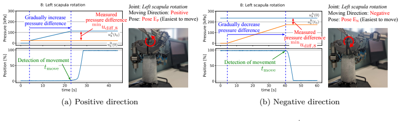
we confirm that the system exhibits highly reproducible behavior... RMSEi(j,k) = sqrt(1/T sum (q_i^j(t) - q_i^k(t))^2)
What do these tags mean?
- matches
- The paper's claim is directly supported by a theorem in the formal canon.
- supports
- The theorem supports part of the paper's argument, but the paper may add assumptions or extra steps.
- extends
- The paper goes beyond the formal theorem; the theorem is a base layer rather than the whole result.
- uses
- The paper appears to rely on the theorem as machinery.
- contradicts
- The paper's claim conflicts with a theorem or certificate in the canon.
- unclear
- Pith found a possible connection, but the passage is too broad, indirect, or ambiguous to say the theorem truly supports the claim.
Reference graph
Works this paper leans on
-
[1]
Physical Human-Robot Interaction: Mutual Learn- ing and Adaptation
Ikemoto S, Amor HB, Minato T, et al. Physical Human-Robot Interaction: Mutual Learn- ing and Adaptation. IEEE Robotics & Automation Magazine. 2012 Dec;19(4):24–35
work page 2012
-
[2]
Pneumatic-driven jumping robot with anthro- pomorphic muscular skeleton structure
Hosoda K, Sakaguchi Y, Takayama H, et al. Pneumatic-driven jumping robot with anthro- pomorphic muscular skeleton structure. Autonomous Robots. 2010 Apr;28(3):307–316
work page 2010
-
[3]
Vanderborght B, Van Ham R, Verrelst B, et al. Overview of the Lucy Project: Dynamic Stabilization of a Biped Powered by Pneumatic Artificial Muscles. Advanced Robotics. 2008 Jan;22(10):1027–1051
work page 2008
-
[4]
Design and Control of a Bio-inspired Human-friendly Robot
Shin D, Sardellitti I, Park YL, et al. Design and Control of a Bio-inspired Human-friendly Robot. The International Journal of Robotics Research. 2010 Apr;29(5):571–584
work page 2010
-
[5]
Soft Actuation and Compliant Mechanisms in Humanoid Robots
Niiyama R. Soft Actuation and Compliant Mechanisms in Humanoid Robots. Current Robotics Reports. 2022 Sep;3(3):111–117
work page 2022
-
[6]
Fatigue characteristics of McKibben artificial muscle actuators
Klute G, Hannaford B. Fatigue characteristics of McKibben artificial muscle actuators. In: Proceedings. 1998 IEEE/RSJ International Conference on Intelligent Robots and Systems. Innovations in Theory, Practice and Applications (Cat. No.98CH36190); Vol. 3; Oct
work page 1998
-
[7]
Fatigue life testing of swaged pneumatic artificial muscles as actuators for aerospace applications
Woods BK, Gentry MF, Kothera CS, et al. Fatigue life testing of swaged pneumatic artificial muscles as actuators for aerospace applications. Journal of Intelligent Material Systems and Structures. 2012 Feb;23(3):327–343
work page 2012
-
[8]
Building Robota, a Mini-Humanoid Robot for the Rehabilitation of Children With Autism
Billard A, Robins B, Nadel J, et al. Building Robota, a Mini-Humanoid Robot for the Rehabilitation of Children With Autism. Assistive Technology. 2007 Mar;19(1):37–49
work page 2007
-
[9]
KASPAR – A Minimally Expressive Humanoid Robot for Human–Robot Interaction Research
Dautenhahn K, Nehaniv CL, Walters ML, et al. KASPAR – A Minimally Expressive Humanoid Robot for Human–Robot Interaction Research. Applied Bionics and Biome- chanics. 2009;6(3-4):708594
work page 2009
-
[10]
Design of 22-DOF pneumatically actuated upper body for child android ‘Affetto’
Ishihara H, Asada M. Design of 22-DOF pneumatically actuated upper body for child android ‘Affetto’ . Advanced Robotics. 2015 Sep;29(18):1151–1163
work page 2015
-
[11]
Ishihara H, Yoshikawa Y, Asada M. Realistic child robot “Affetto” for understanding the caregiver-child attachment relationship that guides the child development. In: 2011 IEEE International Conference on Development and Learning (ICDL); Vol. 2; Aug.; 2011. p. 1–5
work page 2011
-
[12]
Improvement of Pneumatic Robot Control Using Disturbance Observer (in Japanese)
Noritsugu T, Park JG. Improvement of Pneumatic Robot Control Using Disturbance Observer (in Japanese). Journal of the Robotics Society of Japan. 1994;12(4):590–595
work page 1994
-
[13]
Hoshino K. Control of Speed and Power in a Humanoid Robot Arm Using Pneumatic Actuators for Human-Robot Coexisting Environment. IEICE TRANSACTIONS on In- formation and Systems. 2008 Jun;E91-D(6):1693–1699
work page 2008
-
[14]
Murayama E, Yogosawa Y, Kawakami Y, et al. Study on Control Performance with Con- sideration of Articulated Manipulators with Pneumatic Cylinders. International Journal of Automation Technology. 2014 Mar;8(2):159–168. 22
work page 2014
-
[15]
On trajectory tracking control of fluid-driven actuators
Hoffmann K, M¨ uller D, Simon R, et al. On trajectory tracking control of fluid-driven actuators. at - Automatisierungstechnik. 2021 Nov;69(11):970–980
work page 2021
-
[16]
Design of a small pneumatic walking robot Thesis
Binnard MB. Design of a small pneumatic walking robot Thesis. Massachusetts Institute of Technology; 1995
work page 1995
-
[17]
A Pneumatically Actuated Quadrupedal Walking Robot
Wait KW, Goldfarb M. A Pneumatically Actuated Quadrupedal Walking Robot. IEEE/ASME Transactions on Mechatronics. 2014 Feb;19(1):339–347
work page 2014
-
[18]
CB2: A child robot with biomimetic body for cognitive developmental robotics
Minato T, Yoshikawa Y, Noda T, et al. CB2: A child robot with biomimetic body for cognitive developmental robotics. In: 2007 7th IEEE-RAS International Conference on Humanoid Robots; Nov.; 2007. p. 557–562
work page 2007
-
[19]
Identification and control of a pneumatic robot
Todorov E, Hu C, Simpkins A, et al. Identification and control of a pneumatic robot. In: 2010 3rd IEEE RAS EMBS International Conference on Biomedical Robotics and Biomechatronics; Sep.; 2010. p. 373–380
work page 2010
-
[20]
Modeling and identification of pneumatic actuators
Tassa Y, Wu T, Movellan J, et al. Modeling and identification of pneumatic actuators. In: 2013 IEEE International Conference on Mechatronics and Automation; Aug.; 2013. p. 437–443
work page 2013
-
[21]
Tanaka K, Nishikawa S, Niiyama R, et al. Immediate Generation of Jump-and-Hit Mo- tions by a Pneumatic Humanoid Robot Using a Lookup Table of Learned Dynamics. IEEE Robotics and Automation Letters. 2021 Jul;6(3):5557–5564
work page 2021
-
[22]
Pneumatic Drives: System Design, Modelling and Control
Beater P. Pneumatic Drives: System Design, Modelling and Control. Berlin: Springer; 2007
work page 2007
-
[23]
Review on controller design in pneumatic actuator drive system
Jamian S, Salim SNS, Kamarudin MN, et al. Review on controller design in pneumatic actuator drive system. TELKOMNIKA (Telecommunication Computing Electronics and Control). 2020 Feb;18(1):332–342
work page 2020
-
[24]
Kinematics control of a pneumatic system by hybrid fuzzy PID
Parnichkun M, Ngaecharoenkul C. Kinematics control of a pneumatic system by hybrid fuzzy PID. Mechatronics. 2001 Dec;11(8):1001–1023
work page 2001
-
[25]
Model-Based Evolution of a Fast Hybrid Fuzzy Adaptive Controller for a Pneumatic Muscle Actuator
Hoˇ sovsk´ y A, Nov´ ak-Marcinˇ cin J, Pitel’ J, et al. Model-Based Evolution of a Fast Hybrid Fuzzy Adaptive Controller for a Pneumatic Muscle Actuator. International Journal of Advanced Robotic Systems. 2012 Aug;9(2):40
work page 2012
-
[26]
Position control of a pneumatic actuator under the influence of stiction
Hamiti K, Voda-Besan¸ con A, Roux-Buisson H. Position control of a pneumatic actuator under the influence of stiction. Control Engineering Practice. 1996 Aug;4(8):1079–1088
work page 1996
-
[27]
Servo Pneumatic Position Control Using Fuzzy PID Gain Scheduling
Situm Z, Pavkovic D, Novakovic B. Servo Pneumatic Position Control Using Fuzzy PID Gain Scheduling. Journal of Dynamic Systems, Measurement, and Control. 2004 Aug; 126(2):376–387
work page 2004
-
[28]
A robust sliding mode control for pneumatic servo systems
Song J, Ishida Y. A robust sliding mode control for pneumatic servo systems. International Journal of Engineering Science. 1997 Jun;35(8):711–723
work page 1997
-
[29]
Sliding control of an electropneumatic actuator using an integral switching surface
Bouri M, Thomasset D. Sliding control of an electropneumatic actuator using an integral switching surface. IEEE Transactions on Control Systems Technology. 2001 Mar;9(2):368– 375
work page 2001
-
[30]
Multiple-surface sliding controller design for pneumatic servo sys- tems
Tsai YC, Huang AC. Multiple-surface sliding controller design for pneumatic servo sys- tems. Mechatronics. 2008 Nov;18(9):506–512
work page 2008
-
[31]
High-order sliding mode for an electropneumatic sys- tem: A robust differentiator–controller design
Smaoui M, Brun X, Thomasset D. High-order sliding mode for an electropneumatic sys- tem: A robust differentiator–controller design. International Journal of Robust and Non- linear Control. 2008;18(4-5):481–501
work page 2008
-
[32]
Rahman RA, He L, Sepehri N. Design and experimental study of a dynamical adaptive backstepping–sliding mode control scheme for position tracking and regulating of a low- cost pneumatic cylinder. International Journal of Robust and Nonlinear Control. 2016; 26(4):853–875
work page 2016
-
[33]
Ayadi A, Smaoui M, Aloui S, et al. Adaptive sliding mode control with moving surface: Experimental validation for electropneumatic system. Mechanical Systems and Signal Processing. 2018 Sep;109:27–44
work page 2018
-
[34]
Ren HP, Wang X, Fan JT, et al. Adaptive Backstepping Control of a Pneumatic System With Unknown Model Parameters and Control Direction. IEEE Access. 2019;7:64471– 64482
work page 2019
-
[35]
Yang B, Tan UX, McMillan AB, et al. Design and Control of a 1-DOF MRI-Compatible 23 Pneumatically Actuated Robot With Long Transmission Lines. IEEE/ASME Transac- tions on Mechatronics. 2011 Dec;16(6):1040–1048
work page 2011
-
[36]
Model-Based Force Control of Pneumatic Actuators With Long Transmission Lines
Turkseven M, Ueda J. Model-Based Force Control of Pneumatic Actuators With Long Transmission Lines. IEEE/ASME Transactions on Mechatronics. 2018 Jun;23(3):1292– 1302
work page 2018
-
[37]
Butt K, Sepehri N. A Nonlinear Integral Sliding Surface to Improve the Transient Re- sponse of a Force-Controlled Pneumatic Actuator With Long Transmission Lines. Journal of Dynamic Systems, Measurement, and Control. 2019 Sep;141(12). 24
work page 2019
discussion (0)
Sign in with ORCID, Apple, or X to comment. Anyone can read and Pith papers without signing in.