Recognition: 2 theorem links
· Lean TheoremIdeally-Smooth Transition between Grid-Forming and Grid-Following Inverters based on State Mapping Method
Pith reviewed 2026-05-13 16:58 UTC · model grok-4.3
The pith
State mapping method achieves ideally smooth transitions between grid-forming and grid-following inverter modes.
A machine-rendered reading of the paper's core claim, the machinery that carries it, and where it could break.
Core claim
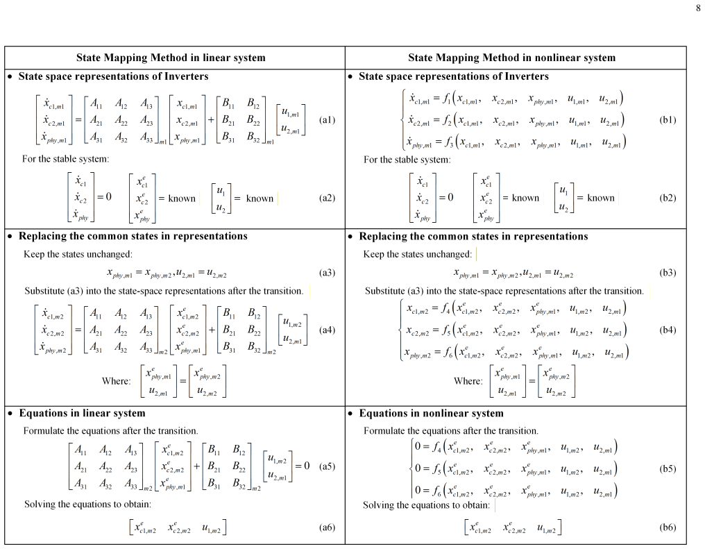
The state mapping method equates the states of the GFM and GFL controllers at the switching moment through a designed transformation, allowing the post-switch control to be initialized so that the inverter output voltage and current continue without any jump or oscillation, thereby realizing an ideally-smooth transition.
What carries the argument
The state mapping method, which constructs an explicit mapping between the pre- and post-switch state vectors to cancel the transient dynamics induced by the change in control law.
If this is right
- Inverters can change between GFM and GFL modes on demand without risking grid instability.
- Renewable plants can respond to source-side limits or grid-side service requests by mode switching in real time.
- Fault ride-through strategies become simpler because mode changes no longer require separate damping controllers.
- The same mapping technique can be applied symmetrically in either direction (GFM to GFL or GFL to GFM).
Where Pith is reading between the lines
- The method could be extended to switches involving additional modes such as virtual synchronous machine or current-limiting controls.
- If the mapping remains accurate under parameter drift, the technique would reduce the need for conservative stability margins in microgrids with frequent mode changes.
- Hardware implementation would require only a one-time computation of the mapping matrix at design time rather than continuous adaptation.
Load-bearing premise
That the chosen state mapping at the single switching instant fully captures every relevant dynamic so that the resulting control law eliminates all oscillations without introducing new unmodeled effects or needing perfect knowledge of system parameters.
What would settle it
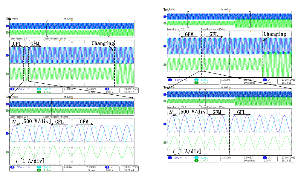
A simulation or hardware test in which the mapped control is applied during a GFM-to-GFL or GFL-to-GFM switch yet measurable voltage or current oscillations still appear at the inverter terminals.
Figures


read the original abstract
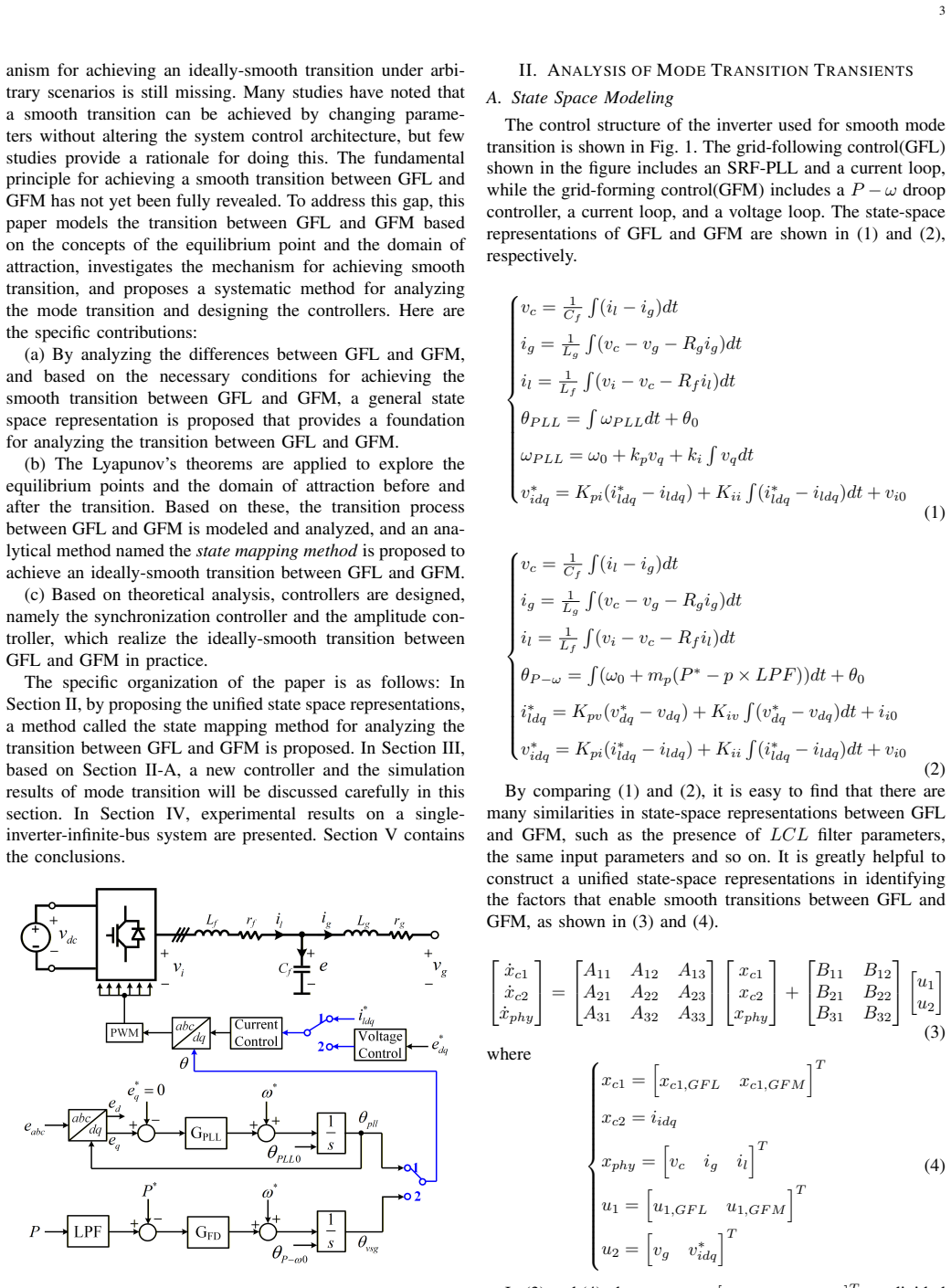
There has been widespread global increasing use of renewable energy sources, which are usually connected to the electricity grids via power electronic inverters. Traditionally, these inverter-based resources operate in either grid-forming (GFM) or grid-following (GFL) mode. But more recently, the need of switching between these two modes are glowingly required because of the complex operation scenarios of systems such as source-side limitations, grid-side services, fault disturbances, etc. However, due to the differences between GFM and GFL modes, a direct switching between them would lead to large oscillations or even instability of inverters. Therefore, in this paper, a method called state mapping method for analyzing the switching transient and designing the switching control is proposed. Based on this method, an ideally-smooth transition between GFM and GFL can be achieved. The effectiveness of the proposed method is verified by both the theoretical analysis and experiment tests.
Editorial analysis
A structured set of objections, weighed in public.
Referee Report
Summary. The paper proposes a state mapping method to analyze switching transients between grid-forming (GFM) and grid-following (GFL) inverter modes and to design a control law that achieves an ideally smooth transition without oscillations. The approach is presented as an analytical tool independent of fitted parameters, with effectiveness verified via theoretical analysis and experimental tests in scenarios involving source limitations, grid services, and faults.
Significance. If the state mapping exactly cancels transients at the switching instant under the modeled conditions, the result would be significant for practical inverter control in renewable-dominated grids, enabling reliable mode transitions without destabilizing oscillations. The method's strength lies in its explicit analytical treatment of the switching dynamics rather than heuristic tuning.
major comments (1)
- [Abstract and method description] The central claim of an 'ideally-smooth transition' rests on the assumption that the state mapping fully cancels transient dynamics, which holds only under exact model match and perfect parameter knowledge (filter parameters, grid impedance, control gains). No sensitivity analysis or robustness margins to mismatches or delays are provided, leaving the claim vulnerable to residual oscillations in practice.
Simulated Author's Rebuttal
We thank the referee for the constructive comments on our manuscript. We address the major comment point by point below and outline the revisions we will make.
read point-by-point responses
-
Referee: [Abstract and method description] The central claim of an 'ideally-smooth transition' rests on the assumption that the state mapping fully cancels transient dynamics, which holds only under exact model match and perfect parameter knowledge (filter parameters, grid impedance, control gains). No sensitivity analysis or robustness margins to mismatches or delays are provided, leaving the claim vulnerable to residual oscillations in practice.
Authors: We agree that the ideally-smooth transition is achieved exactly only when the state mapping is derived under perfect model match and precise knowledge of all parameters, as the method relies on an analytical cancellation of the post-switching dynamics. This assumption is inherent to the derivation and is stated in the theoretical analysis. The experimental results, however, were obtained on a physical testbed that includes real-world effects such as small parameter drifts, measurement noise, and computational delays, and still exhibit negligible oscillations. To directly address the concern, we will add a dedicated sensitivity-analysis subsection in the revised manuscript. This will include (i) analytical bounds on residual transients under bounded parameter mismatches, (ii) Monte-Carlo simulation results quantifying oscillation amplitude versus mismatch levels, and (iii) explicit robustness margins with respect to grid-impedance and delay variations. revision: yes
Circularity Check
State mapping method is an independent derivation with no reduction to inputs by construction
full rationale
The paper introduces a state mapping method as a new analytical tool for switching transients between GFM and GFL modes. The abstract presents the ideally-smooth transition as a consequence of this method's design, verified by theoretical analysis and experiments. No equations or claims in the provided text reduce the central result to a fitted parameter, self-citation chain, or renamed known result. The derivation appears self-contained, with the mapping constructed from system dynamics rather than presupposing the smoothness outcome.
Axiom & Free-Parameter Ledger
Lean theorems connected to this paper
-
IndisputableMonolith/Foundation/RealityFromDistinction.leanreality_from_one_distinction unclearstate mapping method ... equilibrium point of the system before transition is directly mapped to the equilibrium point of the system after transition ... no transient
-
IndisputableMonolith/Cost/FunctionalEquation.leanwashburn_uniqueness_aczel unclearLyapunov’s theorems ... domain of attraction
Reference graph
Works this paper leans on
-
[1]
Revisiting grid-forming and grid-following inverters: A duality theory,
Y . Li, Y . Gu, and T. Green, “Revisiting grid-forming and grid-following inverters: A duality theory,”IEEE Trans. on Power Syst., 2022
work page 2022
-
[2]
Control of power converters in ac microgrids,
J. Rocabert, A. Luna, F. Blaabjerg, and P. Rodriguez, “Control of power converters in ac microgrids,”IEEE transactions on power electronics, vol. 27, no. 11, pp. 4734–4749, 2012
work page 2012
-
[3]
M. Li, X. Zhang, Z. Guo, H. Pan, M. Ma, and W. Zhao, “Impedance adaptive dual-mode control of grid-connected inverters with large fluctu- ation of scr and its stability analysis based on d-partition method,”IEEE 13 Transactions on Power Electronics, vol. 36, no. 12, pp. 14 420–14 435, 2021
work page 2021
-
[4]
A universal controller for grid-connected voltage-source converters,
L. Harnefors, J. Kukkola, M. Routimo, M. Hinkkanen, and X. Wang, “A universal controller for grid-connected voltage-source converters,”IEEE Journal of Emerging and Selected Topics in Power Electronics, vol. 9, no. 5, pp. 5761–5770, 2020
work page 2020
-
[5]
M. Kwon, S. Park, C.-y. Oh, J. Lee, and S. Choi, “Unified control scheme of grid-connected inverters for autonomous and smooth transfer to stand-alone mode,”IEEE Transactions on Power Electronics, vol. 37, no. 1, pp. 416–425, 2021
work page 2021
-
[6]
A unified control strategy for three- phase inverter in distributed generation,
Z. Liu, J. Liu, and Y . Zhao, “A unified control strategy for three- phase inverter in distributed generation,”IEEE Transactions on power electronics, vol. 29, no. 3, pp. 1176–1191, 2013
work page 2013
-
[7]
M. Li, X. Zhang, Z. Guo, J. Wang, and F. Li, “The dual-mode combined control strategy for centralized photovoltaic grid-connected inverters based on double-split transformers,”IEEE TRANSACTIONS ON INDUSTRIAL ELECTRONICS, vol. 68, no. 12, pp. 12 322–12 330, DEC 2021
work page 2021
-
[8]
A novel design for switchable grid-following and grid-forming control,
H. Ding, R. Kar, Z. Miao, and L. Fan, “A novel design for switchable grid-following and grid-forming control,”IEEE Transactions on Sus- tainable Energy, 2024
work page 2024
-
[9]
Seamless transition control method of grid-connected inverters under unbalanced voltage conditions,
H. J. Kim, H. J. Lee, M. S. Kim, and E. S. Lee, “Seamless transition control method of grid-connected inverters under unbalanced voltage conditions,”IEEE Open Journal of Power Electronics, 2025
work page 2025
-
[10]
Y . Cheng, W. Wu, M. Orabi, K. Eftychios, H. Chung, and F. Blaabjerg, “Smooth switching between two different control methods based on kalman filter for grid-connected inverter,” in2024 IEEE 19th Conference on Industrial Electronics and Applications (ICIEA). IEEE, 2024, pp. 1–4
work page 2024
-
[11]
X. Gao, D. Zhou, A. Anvari-Moghaddam, and F. Blaabjerg, “Seamless switching method between grid-following and grid-forming control for renewable energy conversion systems,”IEEE Transactions on Industry Applications, 2024
work page 2024
-
[12]
C. Wang, B. Liang, and J. He, “An enhanced power regulation and seam- less operation mode transfer control through cooperative dual-interfacing converters,”IEEE TRANSACTIONS ON SMART GRID, vol. 9, no. 6, pp. 5576–5587, NOV 2018
work page 2018
-
[13]
M. N. Arafat, A. Elrayyah, and Y . Sozer, “An effective smooth transition control strategy using droop-based synchronization for parallel invert- ers,”IEEE Transactions on Industry Applications, vol. 51, no. 3, pp. 2443–2454, 2014
work page 2014
-
[14]
A graph-theoretic approach for ensuring stability in dc microgrid networks during mode switching,
S. Jiang, Z. Sun, J. Zhang, M. Zhang, C. Tang, X. He, and H. Geng, “A graph-theoretic approach for ensuring stability in dc microgrid networks during mode switching,”IEEE TRANSACTIONS ON SMART GRID, vol. 17, no. 2, pp. 922–935, MAR 2026
work page 2026
-
[15]
W. Wang, K. Sun, K.-J. Li, Y . Dong, Z. Zhang, and Y . Sun, “Smooth switching control strategy with complete process of frequency support for photovoltaic grid-connected converter,”INTERNATIONAL JOUR- NAL OF ELECTRICAL POWER & ENERGY SYSTEMS, vol. 151, SEP 2023
work page 2023
-
[16]
L. Wang, N. Zhou, Y . Shu, X. Zeng, B. Zhao, J. Zhao, and Y . Jiang, “A flexible dual-mode switching strategy for grid-connected energy storage considering fault ride through capability and support for ac microgrid stability,”IEEE TRANSACTIONS ON ENERGY CONVERSION, vol. 40, no. 3, pp. 2587–2598, SEP 2025
work page 2025
-
[17]
An extension of grid-forming: A frequency-following voltage-forming inverter,
C. Ai, Y . Li, Z. Zhao, Y . Gu, and J. Liu, “An extension of grid-forming: A frequency-following voltage-forming inverter,”IEEE TRANSACTIONS ON POWER ELECTRONICS, vol. 39, no. 10, pp. 12 118–12 123, OCT 2024
work page 2024
-
[18]
Y . Li, Y . Gu, Y . Zhu, A. Junyent-Ferre, X. Xiang, and T. C. Green, “Impedance circuit model of grid-forming inverter: Visualizing control algorithms as circuit elements,”IEEE TRANSACTIONS ON POWER ELECTRONICS, vol. 36, no. 3, pp. 3377–3395, MAR 2021
work page 2021
-
[19]
M. Z. Mansour, S. P. Me, S. Hadavi, B. Badrzadeh, A. Karimi, and B. Bahrani, “Nonlinear transient stability analysis of phased-locked loop-based grid-following voltage-source converters using lyapunov’s direct method,”IEEE JOURNAL OF EMERGING AND SELECTED TOPICS IN POWER ELECTRONICS, vol. 10, no. 3, pp. 2699–2709, JUN 2022
work page 2022
-
[20]
X. Fu, J. Sun, M. Huang, Z. Tian, H. Yan, H. H.-C. Iu, P. Hu, and X. Zha, “Large-signal stability of grid-forming and grid-following controls in voltage source converter: A comparative study,”IEEE TRANSACTIONS ON POWER ELECTRONICS, vol. 36, no. 7, pp. 7832–7840, JUL 2021
work page 2021
-
[21]
D. Dong, B. Wen, D. Boroyevich, P. Mattavelli, and Y . Xue, “Analysis of phase-locked loop low-frequency stability in three-phase grid-connected power converters considering impedance interactions,”IEEE TRANSAC- TIONS ON INDUSTRIAL ELECTRONICS, vol. 62, no. 1, pp. 310–321, JAN 2015
work page 2015
-
[22]
M. Huang, Y . Peng, C. K. Tse, Y . Liu, J. Sun, and X. Zha, “Bifur- cation and large-signal stability analysis of three-phase voltage source converter under grid voltage dips,”IEEE TRANSACTIONS ON POWER ELECTRONICS, vol. 32, no. 11, pp. 8868–8879, NOV 2017
work page 2017
discussion (0)
Sign in with ORCID, Apple, or X to comment. Anyone can read and Pith papers without signing in.