REVIEW 2 major objections 2 minor 14 references
LithoGRPO: Fast Inverse Lithography via GRPO Reinforced Flow Matching
T0 review · 2 major / 2 minor · reviewed 2026-06-28 · grok-4.3
Pith's one-line read LithoGRPO integrates flow matching with GRPO reinforcement learning to optimize lithography masks using explicit physics rewards.
desk verdict LithoGRPO claims a first unification of flow matching and GRPO RL for inverse lithography plus a fast shot-counting trick, but the SOTA and 130x speedup assertions sit on unshown experiments. read the letter →
The pith
A machine-rendered reading of the paper's core claim, the machinery that carries it, and where it could break.
The reading
What carries the argument
The GRPO reinforced flow matching framework, which uses flow matching to generate diverse mask candidates and GRPO RL to fine-tune them based on lithography physics rewards.
What would settle it
Direct measurement of printed pattern fidelity on fabricated wafers using LithoGRPO masks versus the simulated physics rewards that guided optimization.
Extended reading notes
Core claim
LithoGRPO unifies the flow matching paradigm with GRPO reinforcement learning for the first time in mask optimization, allowing the model to leverage an explicitly defined physics-based reward function to optimize under complex process-aware constraints, resulting in state-of-the-art performance on inverse lithography tasks.
Load-bearing premise
The physics-based reward function used in the GRPO stage fully and accurately represents all relevant lithography process constraints without significant error or ranking bias.
Editorial analysis
A structured set of objections, weighed in public.
Referee Report
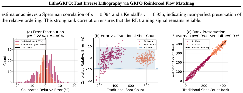
Summary. The paper introduces LithoGRPO, a framework integrating flow-matching generative models with GRPO reinforcement learning for inverse lithography (ILT). It uses an explicitly physics-based reward for mask optimization under process constraints and proposes a fast shot-counting approximation claimed to deliver >130x speedup while preserving traditional shot-count rankings. The central claim is that this yields SOTA performance over both optimization-based and learning-based ILT methods with efficient mask generation.
Significance. If the performance claims and ranking preservation hold under rigorous validation, the work would be significant for semiconductor manufacturing by demonstrating a practical unification of generative flow models with RL fine-tuning on physics-based objectives, potentially enabling faster exploration of manufacturable masks at advanced nodes.
major comments (2)
- [Fast shot-counting algorithm section] Fast shot-counting algorithm section: The claim that the approximation 'preserves the mask ranking of the traditional shot-count metric' is load-bearing for the GRPO stage and the SOTA result, yet no quantitative evidence (e.g., inversion rate, Kendall-tau correlation, or worst-case ranking error on realistic mask distributions) is provided to bound the probability of order inversions that would systematically bias reward signals and policy updates.
- [Experimental results section (performance tables)] Experimental results section (performance tables): The abstract and claims assert SOTA results and 130x speedup, but without reported error bars, number of independent runs, statistical significance tests, or ablation on the contribution of the RL stage versus the base flow model, it is impossible to assess whether the gains are robust or sensitive to post-hoc hyperparameter choices.
minor comments (2)
- [Reward function description] Notation for the composite reward function should be introduced with an explicit equation rather than descriptive text to allow readers to verify how the shot-count term is weighted relative to other physics terms.
- [Experiments] The manuscript should include a clear statement of the exact baselines (specific prior ILT methods and their implementations) used for the SOTA comparison.
Simulated Author's Rebuttal
We thank the referee for the constructive comments highlighting the need for stronger validation of the fast shot-counting approximation and more rigorous experimental reporting. We address each point below and will incorporate the suggested additions in the revised manuscript.
read point-by-point responses
-
Referee: [Fast shot-counting algorithm section] Fast shot-counting algorithm section: The claim that the approximation 'preserves the mask ranking of the traditional shot-count metric' is load-bearing for the GRPO stage and the SOTA result, yet no quantitative evidence (e.g., inversion rate, Kendall-tau correlation, or worst-case ranking error on realistic mask distributions) is provided to bound the probability of order inversions that would systematically bias reward signals and policy updates.
Authors: We agree that quantitative validation of ranking preservation is essential given its role in the GRPO reward signal. In the revised manuscript we will add a dedicated evaluation subsection reporting Kendall-tau correlation, inversion rates, and worst-case ranking error on a collection of realistic mask distributions drawn from the test set. These metrics will directly bound the risk of order inversions. revision: yes
-
Referee: [Experimental results section (performance tables)] Experimental results section (performance tables): The abstract and claims assert SOTA results and 130x speedup, but without reported error bars, number of independent runs, statistical significance tests, or ablation on the contribution of the RL stage versus the base flow model, it is impossible to assess whether the gains are robust or sensitive to post-hoc hyperparameter choices.
Authors: We acknowledge that the current experimental section lacks these statistical elements. The revised version will report results over multiple independent runs with error bars, include statistical significance tests, and add an ablation study that isolates the contribution of the GRPO fine-tuning stage relative to the base flow-matching model. revision: yes
Circularity Check
No significant circularity detected
full rationale
The abstract and description present LithoGRPO as a framework that combines an existing flow-matching base model with GRPO RL fine-tuning using an explicitly defined physics-based reward function. The fast shot-counting algorithm is described as an empirical approximation claimed to preserve ranking, but this is presented as a practical speedup rather than a definitional reduction or fitted input renamed as prediction. No equations are shown that reduce a claimed derivation to its own inputs by construction, no self-citation chains are load-bearing for the core result, and the SOTA claim rests on experimental comparisons rather than self-referential definitions. This is the common case of a self-contained applied method without circularity in the derivation chain.
Assumptions & free parameters
Cite this review
Pith. "Pith review of LithoGRPO: Fast Inverse Lithography via GRPO Reinforced Flow Matching." pith.science (2026). https://pith.science/paper/DBRBFSL3
@misc{pith2026260600228,
  author       = {Pith},
  title        = {Pith review of: LithoGRPO: Fast Inverse Lithography via GRPO Reinforced Flow Matching},
  year         = {2026},
  howpublished = {\url{https://pith.science/paper/DBRBFSL3}},
  note         = {Machine review of arXiv:2606.00228}
}
read the original abstract
In semiconductor manufacturing, lithography projects circuit layouts onto silicon wafers through an optical mask. As circuit features shrink below the wavelength of light, optical diffraction causes the printed patterns to deviate from their intended layouts. Inverse Lithography Technology (ILT) addresses this challenge by generating optimized masks that enhance the fidelity of pattern transfer onto wafers. While ILT resembles an image synthesis task, its reliance on explicit physical metrics for mask evaluation limits the applicability of existing generative models. We introduce LithoGRPO, an ILT framework that integrates the flow-matching paradigm with GRPO-based reinforcement learning (RL) fine-tuning, enabling efficient exploration of diverse masks for a given target layout. Unlike purely generative or optimization-based approaches, RL in LithoGRPO exploits the explicitly defined, physics-based reward function of ILT, enabling optimization under complex, process-aware constraints. To the best of our knowledge, this is the first framework that unifies flow matching and RL for mask optimization. To improve RL sampling efficiency, we propose a fast shot-counting algorithm for manufacturability evaluation, achieving over 130x speedup while preserving the mask ranking of the traditional shot-count metric. Extensive experiments demonstrate that LithoGRPO achieves state-of-the-art performance over both optimization-based and learning-based methods, while maintaining efficient mask generation.
Figures


Figures from the paper (10 more)



Reference graph
Works this paper leans on
-
[1]
uses calibrated lithography and resist models to predict wafer contours and iteratively updates mask edges to minimize objective functions such as EPE and CD errors, achieving higher accuracy at the cost of heavier computation. Sub-resolution assist features (SRAFs) (Alawieh et al., 2019; Xu et al., 2016; Liu et al., 2022) are commonly inserted as a resol...
2019
-
[2]
have been adapted to diffusion models, facilitating preference alignment and enhancing task-specific outcomes. In a similar vein, Flow-GRPO (Liu et al., 2025b) and DanceGRPO (Xue et al., 2025) incorporate GRPO-style policy optimization into flow-matching frameworks by reformulating deterministic ODE sampling as stochastic SDE processes, thereby introducin...
2025
-
[3]
, N−1} maintain a height array h[c] that counts the number of consecutive 1’s directly above (and including) pixel(r, c)
For every row r∈ {0, . . . , N−1} maintain a height array h[c] that counts the number of consecutive 1’s directly above (and including) pixel(r, c)
-
[4]
largest rectangle in a histogram
Treat h[·] as a histogram and, in O(N) time, enumerateallmaximal rectangles whose bottom edge lies on row r using the classic monotonic-stack algorithm for the “largest rectangle in a histogram” problem. For example, in an 8×8 binary mask, the maximal rectangles forr∈ {0,1,2,3,5}are shown in Fig. 11
-
[5]
𝑁 = 8 𝒓 = 𝟎 𝒓 = 𝟏 𝒓 = 𝟐 𝒓 = 𝟑 𝒓 = 𝟓 …… 0 1 2 3 4 5 6 7 Figure 11.Visualization of maximal-rectangle generation.Left: an 8×8 binary mask, where colored (filled) pixels indicate 1’s
Append every rectangle found in the second step to the candidate setR all; letK all =|R all|. 𝑁 = 8 𝒓 = 𝟎 𝒓 = 𝟏 𝒓 = 𝟐 𝒓 = 𝟑 𝒓 = 𝟓 …… 0 1 2 3 4 5 6 7 Figure 11.Visualization of maximal-rectangle generation.Left: an 8×8 binary mask, where colored (filled) pixels indicate 1’s. Right: maximal rectangles enumerated for selected rowsr∈ {0,1,2,3,5}, where each r...
2015
-
[6]
Sort all rectangles by area in descending order
-
[7]
For every rectangle, test whether it is contained in any rectangle that has already been kept
-
[8]
After this step, we obtain a pruned set of rectangles, denoted by Rpruned, and define K=|R pruned|
Append the rectangle to the pruned setR pruned iff it is not contained. After this step, we obtain a pruned set of rectangles, denoted by Rpruned, and define K=|R pruned|. The procedure needs O K 2 all comparisons in the worst case, yet it is fast in practice because Kall ≪N 2 for real masks. For extremely large instances, one can switch to the O(Kall log...
Show all 14 references
-
[9]
For example, if M(r,·) = 0011110011100 , then the RLE segments are(s, e) = (2,5)and(8,10)(0-indexed)
For each row r, compute the run-length encoding (RLE) of M(r,·) , i.e., the set of maximal contiguous foreground segments (s, e) such that M(r, c) = 1 for all c∈[s, e] . For example, if M(r,·) = 0011110011100 , then the RLE segments are(s, e) = (2,5)and(8,10)(0-indexed)
-
[10]
For each rowrcollect the rectangles that intersect it,R r ={R i |R i ∩rowr̸=∅}
-
[11]
For example, with RLE segments (2,5) and(8,10)and rectangles spanning[1,6),[4,9), and[8,12)on rowr, we collect{1,6,4,9,8,12} ∪ {2,5,8,10}
Collect thecritical x-coordinates in row r at which coverage can change: the left/right x-boundaries of all rectangles in Rr, together with the endpoints s, e of the foreground RLE segments in row r. For example, with RLE segments (2,5) and(8,10)and rectangles spanning[1,6),[4...
-
[12]
Consecutive pairs define intervals on which the set of covering rectangles is constant
Sort and deduplicate the critical coordinates. Consecutive pairs define intervals on which the set of covering rectangles is constant. For the example above, sorting yields {1,2,4,5,6,8,9,10,12} and thus the intervals [1,2),[2,4),[4,5), . . . ,[10,12)
-
[13]
For example, if an interval is [4,5) and on row r it is covered by exactly R1 and R2, we may choosec= 4and addx 1 +x 2 ≥1
For every interval that overlaps foreground pixels, insert one covering constraint using any representative columnc inside that interval:P i:c∈R i xi ≥1. For example, if an interval is [4,5) and on row r it is covered by exactly R1 and R2, we may choosec= 4and addx 1 +x 2 ≥1. ...
-
[14]
These points define Θ(kr +t r) intervals
Scan-line constraint generation.For each row r, we collect Θ(kr +t r) critical x-coordinates and sort them in O((kr +t r) log(kr +t r)) time. These points define Θ(kr +t r) intervals. For every interval overlapping foreground pixels, we add one covering constraint; in the simp...
2023
Reviewed June 28, 2026 · model on record in the stance chip above.
Discussion (0). Sign in to comment.