Package-Embedded Coupled Inductor Arrays for High-Performance Computing Power Delivery
Pith reviewed 2026-06-28 12:59 UTC · model grok-4.3
The pith
Package-embedded arrays of coupled inductors deliver 5.65 percent average efficiency gains in multi-phase power converters.
A machine-rendered reading of the paper's core claim, the machinery that carries it, and where it could break.
Core claim
The central claim is that an array of tightly coupled spiral square inductors sharing one magnetic rod, placed inside the package and paired with an inductance-island partitioning method, simultaneously raises both inductance density and current density while cutting conversion losses in vertical power delivery networks for high-performance computing.
What carries the argument
The package-embedded coupled inductor array in which multiple spiral square inductors share a common magnetic rod and serve converters of the same phase, optimized jointly with the active circuitry through 3D electromagnetic extraction and circuit co-simulation.
If this is right
- The inductance-island approach allows the power delivery network to scale by adding more islands without redesigning the entire converter.
- Joint optimization of the coupled passive array and the active switches produces concrete efficiency gains that grow with load current.
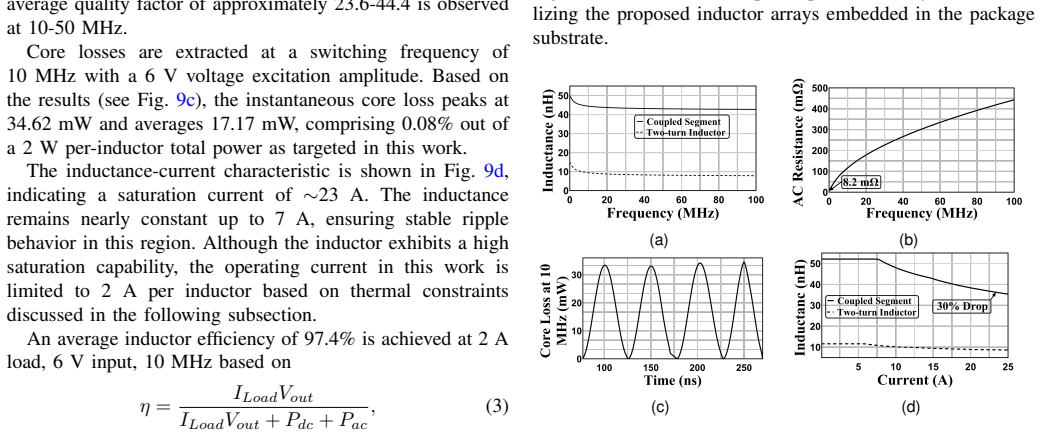
- The topology maintains an average quality factor of 23.6 while operating at 10 MHz, supporting the high switching frequencies needed for compact converters.
Where Pith is reading between the lines
- If the simulated gains hold in hardware, the method could reduce the fraction of total system power lost in delivery, freeing budget for more compute cores or higher clock rates.
- The shared-rod geometry may be adapted to other multi-phase buck or boost stages that already use vertical power paths.
- Successful physical validation would open a route to further density improvements by exploring different rod materials or spiral geometries within the same package constraints.
Load-bearing premise
The 3D electromagnetic simulations and subsequent circuit co-simulations accurately capture all relevant parasitics, material properties, and fabrication effects so the reported densities and efficiency numbers will appear in physical silicon.
What would settle it
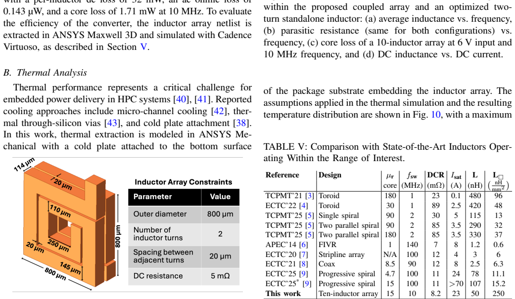
Fabricate the described inductor array in silicon, measure its inductance density, current density, and efficiency at the stated operating point, and compare the results directly to the simulated values of 250 nH/mm², 10 A/mm², and 97.4 percent.
Figures
read the original abstract
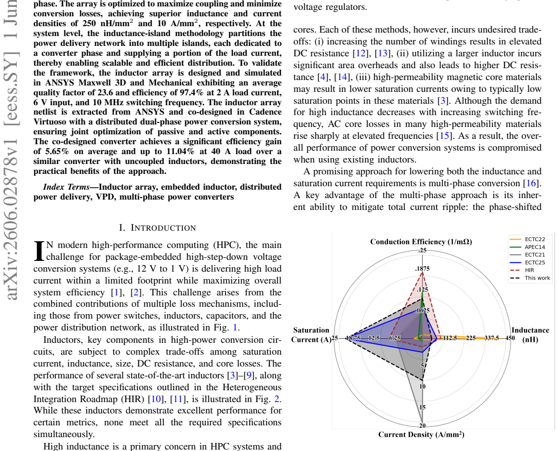
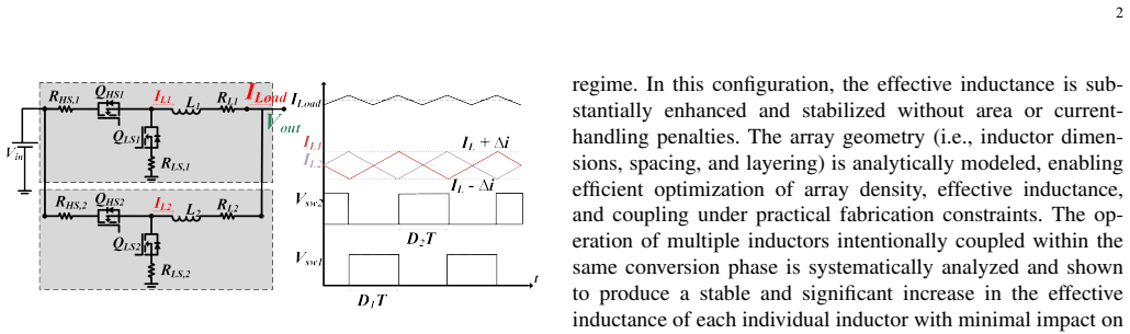
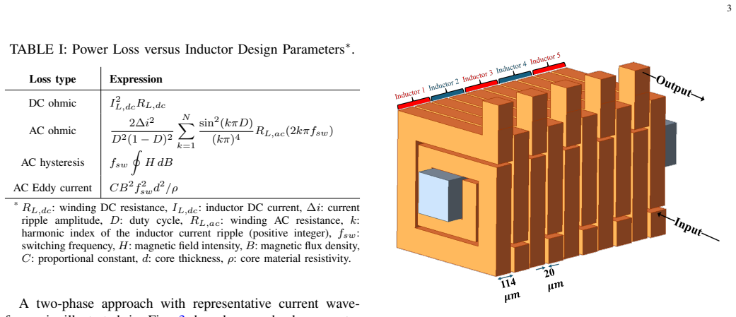
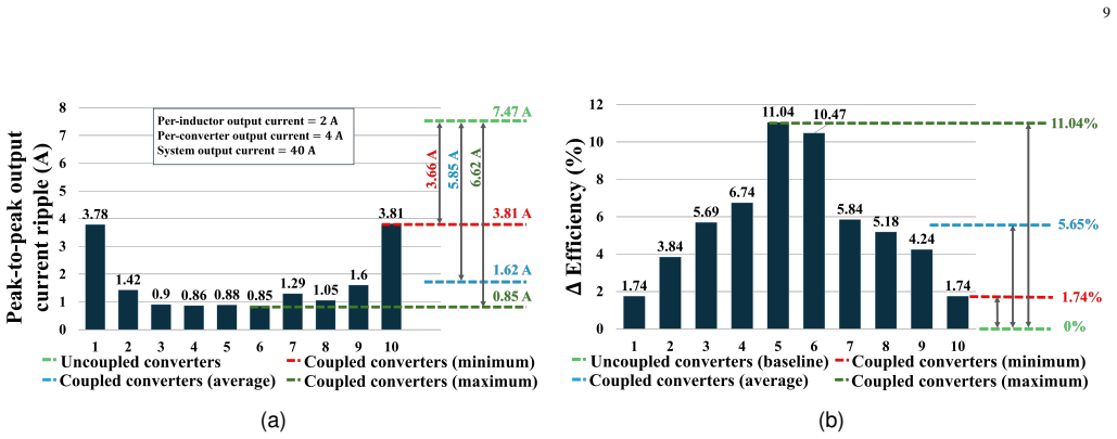
A novel power delivery framework, comprising a package-embedded inductor topology and an inductance-island methodology, is introduced to maximize both inductance and current densities in vertical power delivery (VPD). The framework leverages multiple multi-phase converters, a common strategy in high-performance computing systems, to enhance efficiency and scalability. The proposed topology employs an array of tightly coupled spiral square inductors sharing a common magnetic rod, serving multiple converters operating in the same conversion phase. The array is optimized to maximize coupling and minimize conversion losses, achieving superior inductance and current densities of 250 nH/mm^2 and 10 A/mm^2, respectively. At the system level, the inductance-island methodology partitions the power delivery network into multiple islands, each dedicated to a converter phase and supplying a portion of the load current, thereby enabling scalable and efficient distribution. To validate the framework, the inductor array is designed and simulated in ANSYS Maxwell 3D and Mechanical, exhibiting an average quality factor of 23.6 and efficiency of 97.4% at 2 A load current, 6 V input, and 10 MHz switching frequency. The inductor array netlist is extracted from ANSYS and co-designed in Cadence Virtuoso with a distributed dual-phase power conversion system, ensuring joint optimization of passive and active components. The co-designed converter achieves a significant efficiency gain of 5.65% on average and up to 11.04% at 40 A load over a similar converter with uncoupled inductors, demonstrating the practical benefits of the approach.
Editorial analysis
A structured set of objections, weighed in public.
Referee Report
Summary. The manuscript proposes a package-embedded array of tightly coupled square spiral inductors sharing a common magnetic rod, combined with an 'inductance-island methodology' that partitions the power delivery network into phase-dedicated islands. The design is intended for vertical power delivery in high-performance computing multi-phase converters. All quantitative results—inductance density of 250 nH/mm², current density of 10 A/mm², inductor efficiency of 97.4 % at 2 A / 10 MHz, and converter efficiency gains of 5.65 % average (up to 11.04 % at 40 A) versus an uncoupled baseline—are obtained from ANSYS Maxwell 3D electromagnetic extraction followed by Cadence Virtuoso co-simulation of a dual-phase converter.
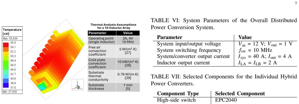
Significance. If the reported simulation fidelity holds in fabricated hardware, the coupled-inductor array and island partitioning could improve both power density and conversion efficiency in package-level VPD, a relevant direction for HPC systems. The explicit use of commercial 3D EM and circuit solvers with stated operating points is a methodological strength, but the complete absence of measured prototypes or independent analytical benchmarks limits the immediate engineering impact.
major comments (2)
- [Simulation results and co-design sections (as described in the abstract and validation narrative)] The headline claims (250 nH/mm² inductance density, 10 A/mm² current density, 97.4 % inductor efficiency, and the 5.65 % / 11.04 % system efficiency gains) rest exclusively on the accuracy of the ANSYS Maxwell 3D model at 10 MHz for a shared-rod, package-embedded geometry. No mesh-convergence data, material-property validation, 2-D analytical cross-check, or measured prototype is provided, so any systematic error in skin-effect, proximity-effect, or inter-winding capacitance extraction propagates directly into the central performance assertions.
- [System-level co-simulation results] The comparison to the 'similar converter with uncoupled inductors' is performed entirely within the same simulation framework. Without an independent baseline (either measured or analytically derived) or a sensitivity study on coupling-coefficient mismatch, it is unclear whether the reported relative gain is robust to realistic fabrication variations in the shared magnetic rod.
minor comments (2)
- The term 'inductance-island methodology' is introduced without a concise algorithmic description or pseudocode; a short dedicated subsection would clarify how the partitioning is performed and how it interacts with the multi-phase converter scheduling.
- Figure captions and text should explicitly state the exact load current, input voltage, and switching frequency at which each efficiency number is reported to avoid ambiguity when comparing the 2 A inductor efficiency figure with the 40 A system-level figure.
Simulated Author's Rebuttal
We thank the referee for the constructive comments on our manuscript. We address each major comment below and indicate where revisions will be made to strengthen the validation sections.
read point-by-point responses
-
Referee: [Simulation results and co-design sections (as described in the abstract and validation narrative)] The headline claims (250 nH/mm² inductance density, 10 A/mm² current density, 97.4 % inductor efficiency, and the 5.65 % / 11.04 % system efficiency gains) rest exclusively on the accuracy of the ANSYS Maxwell 3D model at 10 MHz for a shared-rod, package-embedded geometry. No mesh-convergence data, material-property validation, 2-D analytical cross-check, or measured prototype is provided, so any systematic error in skin-effect, proximity-effect, or inter-winding capacitance extraction propagates directly into the central performance assertions.
Authors: We agree that additional simulation validation is warranted. In the revised manuscript we will add mesh-convergence results from ANSYS Maxwell showing stabilization of inductance and AC resistance with increasing mesh density, explicit material-property values drawn from the simulator library, and a 2-D analytical cross-check for single-spiral inductance using established formulas. These additions will be placed in a new subsection of the validation section. Measured prototypes remain outside the scope of the present simulation study. revision: partial
-
Referee: [System-level co-simulation results] The comparison to the 'similar converter with uncoupled inductors' is performed entirely within the same simulation framework. Without an independent baseline (either measured or analytically derived) or a sensitivity study on coupling-coefficient mismatch, it is unclear whether the reported relative gain is robust to realistic fabrication variations in the shared magnetic rod.
Authors: We will add a sensitivity study in the revised manuscript that varies the coupling coefficient by ±10 % around the extracted value and reports the resulting range of efficiency gains. The uncoupled baseline is obtained by setting mutual inductance to zero within the identical extracted netlist, preserving consistency of all other parasitics. While an independent analytical model for the full 3-D array geometry is not feasible, the sensitivity results will quantify robustness to rod-related variations. revision: yes
- Provision of measured prototype data or hardware validation, as the work is entirely based on electromagnetic and circuit simulation.
Circularity Check
No circularity: results are direct simulation outputs
full rationale
The paper's central claims (250 nH/mm² inductance density, 10 A/mm² current density, 97.4% inductor efficiency, 5.65% avg / 11.04% peak system efficiency gain) are obtained from ANSYS Maxwell 3D EM simulation, netlist extraction, and Cadence Virtuoso co-simulation of the dual-phase converter. These quantities are not algebraically forced by any fitted parameters, self-citations, or input definitions; they are independent numerical outputs of external solvers. No self-definitional equations, fitted-input predictions, load-bearing self-citations, uniqueness theorems, or ansatz smuggling appear in the text. The derivation chain is self-contained against the simulation benchmarks.
Axiom & Free-Parameter Ledger
axioms (1)
- standard math Maxwell's equations and the material models inside ANSYS Maxwell 3D govern inductor behavior
invented entities (1)
-
inductance-island methodology
no independent evidence
Reference graph
Works this paper leans on
-
[1]
Power delivery for high-performance microprocessors—challenges, solutions, and future trends,
K. Radhakrishnan, M. Swaminathan, and B. K. Bhattacharyya, “Power delivery for high-performance microprocessors—challenges, solutions, and future trends,”IEEE Transactions on Components, Packaging and Manufacturing Technology, vol. 11, no. 4, pp. 655–671, 2021
2021
-
[2]
Vertical power delivery for emerging packaging and integration platforms—power conversion and distribution,
S. Krishnakumar and I. Partin-Vaisband, “Vertical power delivery for emerging packaging and integration platforms—power conversion and distribution,” inIEEE International System-on-Chip Conference (SOCC), 2023, pp. 1–6
2023
-
[3]
Embedded inductors using composite magnetic materials for 12–1-V integrated voltage regulators,
C. A. Barros, P. Murali, M. Swaminathan, O. Yusuke, T. Junichi, N. Ryo, and N. Watanabe, “Embedded inductors using composite magnetic materials for 12–1-V integrated voltage regulators,”IEEE Transactions on Components, Packaging and Manufacturing Technology, vol. 11, no. 12, pp. 2183–2192, 2021
2021
-
[4]
Fabrication and characterization of package embedded inductors for integrated voltage regulators,
P. Murali, V . Avula, M. Ahmed, M. D. Losego, M. Swaminathan, C. Alvarez, Y . Oishi, T. Uemura, R. Nagatsuka, and N. Watanabe, “Fabrication and characterization of package embedded inductors for integrated voltage regulators,” inIEEE Electronic Components and Technology Conference (ECTC), 2022, pp. 301–305
2022
-
[5]
Design and demonstration of dual-core spiral package-embedded inductors for integrated voltage regulators,
V . Avula, P. Murali, and M. Swaminathan, “Design and demonstration of dual-core spiral package-embedded inductors for integrated voltage regulators,”IEEE Transactions on Components, Packaging and Manu- facturing Technology, 2025
2025
-
[6]
FIVR—fully integrated voltage regulators on 4th generation Intel® Core™ SoCs,
E. A. Burton, G. Schrom, F. Paillet, J. Douglas, W. J. Lambert, K. Radhakrishnan, and M. J. Hill, “FIVR—fully integrated voltage regulators on 4th generation Intel® Core™ SoCs,” inIEEE Applied Power Electronics Conference and Exposition (APEC), 2014, pp. 432– 439
2014
-
[7]
Magnetic inductor arrays for intel® fully integrated voltage regulator (FIVR) on 10 th generation Intel® Core™ SoCs,
M. Sankarasubramanian, K. Radhakrishnan, Y . Min, W. Lambert, M. J. Hill, A. Dani, R. Mesch, L. Wojewoda, J. Chavarria, and A. Augustine, “Magnetic inductor arrays for intel® fully integrated voltage regulator (FIVR) on 10 th generation Intel® Core™ SoCs,” inIEEE Electronic Components and Technology Conference (ECTC), 2020, pp. 399–404
2020
-
[8]
Integrated voltage regulator efficiency improvement using coaxial magnetic com- posite core inductors,
K. Bharath, K. Radhakrishnan, M. J. Hill, P. Chatterjee, H. Hariri, S. Venkataraman, H. T. Do, L. Wojewoda, and S. Srinivasan, “Integrated voltage regulator efficiency improvement using coaxial magnetic com- posite core inductors,” inIEEE Electronic Components and Technology Conference (ECTC), 2021, pp. 1286–1292
2021
-
[9]
High aspect ratio spiral inductor with progressive turn widths for embedded power converters,
R. Rasheedi and I. Partin-Vaisband, “High aspect ratio spiral inductor with progressive turn widths for embedded power converters,” inIEEE Electronic Components and Technology Conference (ECTC), 2025, pp. 2271–2277
2025
-
[10]
Heterogeneous integration roadmap: Chapter 10 – integrated power electronics (HIR 2023 edi- tion),
IEEE Electronics Packaging Society (EPS), “Heterogeneous integration roadmap: Chapter 10 – integrated power electronics (HIR 2023 edi- tion),” [Online] Available: https://eps.ieee.org/images/files/HIR 2023/ ch10 power.pdf, 2023
2023
-
[11]
MAPT microelectronics and advanced packaging technologies roadmap (version 4),
Semiconductor Research Corporation (SRC), “MAPT microelectronics and advanced packaging technologies roadmap (version 4),” Tech. Rep., Mar. 2023. [Online]. Available: https://srcmapt.org/wp-content/uploads/ 2024/03/SRC-MAPT-Roadmap-2023-v4.pdf
2023
-
[12]
High-q three-dimensional mi- crofabricated magnetic-core toroidal inductors for power supplies in package,
H. T. Le, Y . Nour, Z. Pavlovic, C. O’Math ´una, A. Knott, F. Jensen, A. Han, S. Kulkarni, and Z. Ouyang, “High-q three-dimensional mi- crofabricated magnetic-core toroidal inductors for power supplies in package,”IEEE Transactions on Power Electronics, vol. 34, no. 1, pp. 74–85, 2019
2019
-
[13]
On-chip thin film inductor for high frequency dc-dc power conversion applications,
S. L. Selvaraj, M. Haug, C. S. Cheng, D. Dinulovic, L. Peng, K. E. Shafey, Z. Ali, M. Shousha, Y . C. Ng, N. Aziz Yosokumoro, L. Lehmann, and M. Wieland, “On-chip thin film inductor for high frequency dc-dc power conversion applications,” inIEEE Applied Power Electronics Conference and Exposition (APEC), 2020, pp. 176–180
2020
-
[14]
PCB embedded toroidal inductor for 2MHz point-of-load converter,
R. Murphy, Z. Pavlovic, P. McCloskey, C. O Mathuna, S. O’Driscoll, and G. Weidinger, “PCB embedded toroidal inductor for 2MHz point-of-load converter,” inInternational Conference on Integrated Power Electronics Systems, 2020, pp. 1–5
2020
-
[15]
Soft mag- netic materials for power inductors: State of art and future development,
J. He, H. Yuan, M. Nie, H. Guo, H. Yu, Z. Liu, and R. Sun, “Soft mag- netic materials for power inductors: State of art and future development,” Materials Today Electronics, p. 100066, 2023
2023
-
[16]
Design considerations of multi-phase buck dc-dc converter,
N. Hinov and T. Grigorova, “Design considerations of multi-phase buck dc-dc converter,”Applied Sciences, vol. 13, no. 19, p. 11064, 2023
2023
-
[17]
Vertical power delivery for 1000 Amps machine learning ASICs,
H. Gan, S. Jiang, S. Teng, S. Yamamoto, V . Chivukula, B. Edwards, C. Chung, J. Chen, M. Mohideen, G. Sizikov, and X. Li, “Vertical power delivery for 1000 Amps machine learning ASICs,” inIEEE Applied Power Electronics Conference and Exposition (APEC), 2024, pp. 906– 909
2024
-
[18]
Organic package substrate embedded coupled magnetic core inductors using lithographic via technology for power supply in package,
W. Zhang, G. Zhou, Y . Hong, X. Chen, B. Huang, X. Xu, S. Ding, Z. Zhu, Y . Huang, and W. He, “Organic package substrate embedded coupled magnetic core inductors using lithographic via technology for power supply in package,”Results in Physics, vol. 60, p. 107628, 2024
2024
-
[19]
Fan-out-package-embedded coupled inductors for integrated voltage conversion,
Y . Ding, X. Fang, R. Wu, and J. K. Sin, “Fan-out-package-embedded coupled inductors for integrated voltage conversion,” in2020 32nd International Symposium on Power Semiconductor Devices and ICs (ISPSD). IEEE, 2020, pp. 356–359
2020
-
[20]
A novel thin film cascade matrix coupled inductor for integrated voltage regulators,
N. Wang, H. Zhou, Z. Zhang, S. Peng, J. Yu, Z. Liao, M. Cheng, C. Feeney, L. Liu, and T. Ye, “A novel thin film cascade matrix coupled inductor for integrated voltage regulators,”IEEE Transactions on Power Electronics, vol. 36, no. 12, pp. 13 349–13 354, 2021
2021
-
[21]
Performance improvements of interleaving vrms with coupling inductors,
P.-L. Wong, P. Xu, P. Yang, and F. C. Lee, “Performance improvements of interleaving vrms with coupling inductors,”IEEE Transactions on Power Electronics, vol. 16, no. 4, pp. 499–507, 2001
2001
-
[22]
Butterfly interleaving winding arrangements for multiphase coupled inductors,
M. Li, Y . Liu, Z. Ouyang, and M. A. Andersen, “Butterfly interleaving winding arrangements for multiphase coupled inductors,”IEEE Trans- actions on Power Electronics, vol. 38, no. 3, pp. 3315–3327, 2022
2022
-
[23]
Mini-lego: A 1.5-mhz 240-a 48-v-to-1-v cpu vrm with 8.4-mm height for vertical power delivery,
Y . Elasser, J. Baek, K. Radhakrishnan, H. Gan, J. Douglas, V . De, S. Jiang, H. K. Krishnamurthy, X. Li, C. R. Sullivanet al., “Mini-lego: A 1.5-mhz 240-a 48-v-to-1-v cpu vrm with 8.4-mm height for vertical power delivery,” in2023 IEEE Applied Power Electronics Conference and Exposition (APEC). IEEE, 2023, pp. 1959–1966
2023
-
[24]
Air-lego: A magnetic-free ultra-thin 24v-to-1v 120a vrm with air-coupled inductors,
H. Li, W. Zeng, Y . Elasser, and M. Chen, “Air-lego: A magnetic-free ultra-thin 24v-to-1v 120a vrm with air-coupled inductors,” in2025 IEEE Applied Power Electronics Conference and Exposition (APEC). IEEE, 2025, pp. 510–517
2025
-
[25]
Mini-lego cpu voltage regulator,
Y . Elasser, J. Baek, K. Radhakrishnan, H. Gan, J. P. Douglas, H. K. Krishnamurthy, X. Li, S. Jiang, V . De, C. R. Sullivanet al., “Mini-lego cpu voltage regulator,”IEEE Transactions on Power Electronics, vol. 39, no. 3, pp. 3391–3410, 2023
2023
-
[26]
Coupled inductors with an adaptive coupling coefficient for multiphase voltage regulators,
F. Zhu and Q. Li, “Coupled inductors with an adaptive coupling coefficient for multiphase voltage regulators,”IEEE Transactions on Power Electronics, vol. 38, no. 1, pp. 739–749, 2022
2022
-
[27]
S. Abdelzaher, M. Gharib, and I. Partin-Vaisband, “Hybrid voltage regulators for high performance computing: Analytical models and design methodology,” inIEEE Electronic Components and Technology Conference (ECTC), 2025, pp. 2286–2292, doi:10.1109/ECTC51687.2025.00388
-
[28]
A regulated 48V-to-1V/100A 90.9%-efficient hybrid converter for POL applications in data centers and telecommu- nication systems,
R. Das and H.-P. Le, “A regulated 48V-to-1V/100A 90.9%-efficient hybrid converter for POL applications in data centers and telecommu- nication systems,” inIEEE Applied Power Electronics Conference and Exposition (APEC), Mar 2019, pp. 1997–2001
2019
-
[29]
A 48 V-1 V auxiliary-assisted hybrid dc–dc converter with flying-capacitor-based virtual bus for fast transient response,
N. Khan, O. Cobani, G. V . Piqu ´e, J. Pigott, H. J. Bergveld, and O. Trescases, “A 48 V-1 V auxiliary-assisted hybrid dc–dc converter with flying-capacitor-based virtual bus for fast transient response,”IEEE Transactions on Power Electronics, vol. 39, no. 5, pp. 5848–5861, 2024
2024
-
[30]
A 5 MHz, 12 V, 10 A, monolithically integrated two-phase series capacitor buck converter,
P. S. Shenoy, O. Lazaro, R. Ramani, M. Amaro, W. Wiktor, J. Khayat, and B. Lynch, “A 5 MHz, 12 V, 10 A, monolithically integrated two-phase series capacitor buck converter,” inIEEE Applied Power Electronics Conference and Exposition (APEC), Mar 2016, pp. 66–72
2016
-
[31]
High-efficiency nonisolated con- verter with very high step-down conversion ratio,
O. Kirshenboim and M. M. Peretz, “High-efficiency nonisolated con- verter with very high step-down conversion ratio,”IEEE Transactions on Power Electronics, vol. 32, no. 5, pp. 3683–3690, 2016
2016
-
[32]
Multiphase control for robust and complete soft-charging operation of dual inductor hybrid converter,
T. Xie, R. Das, G.-S. Seo, D. Maksimovic, and H.-P. Le, “Multiphase control for robust and complete soft-charging operation of dual inductor hybrid converter,” inIEEE Applied Power Electronics Conference and Exposition (APEC), Mar 2019, pp. 1–5
2019
-
[33]
Heterogeneous integration roadmap: Chapter 23 – wafer-level packaging (wlp),
IEEE Electronics Packaging Society, “Heterogeneous integration roadmap: Chapter 23 – wafer-level packaging (wlp),” IEEE Electronics Packaging Society (EPS), Tech. Rep., 2021, heterogeneous Integration Roadmap (HIR). [Online]. Available: https://eps.ieee.org/wp-content/ uploads/2025/11/ch23-wlpfinal2.pdf 11
2021
-
[34]
High-efficiency PCB-embeddable inductor for vertical power IVR applications,
Y . Kandeel, L. Ye, J. Flannery, C. O. Math ´una, R. Sai, S. O’Driscoll, T. Tsuchida, N. Terauchi, S. Kishimoto, T. Hiraoka, and M. Nagano, “High-efficiency PCB-embeddable inductor for vertical power IVR applications,” inIEEE Applied Power Electronics Conference and Ex- position (APEC), 2025, pp. 285–290
2025
-
[35]
An embedded multi-layer spiral square inductor for integrated power delivery-physical design and ana- lytical models,
R. Rasheedi and I. Partin-Vaisband, “An embedded multi-layer spiral square inductor for integrated power delivery-physical design and ana- lytical models,” inProceedings of the Great Lakes Symposium on VLSI, 2024, pp. 370–375
2024
-
[36]
Inductance calculations–new york,
F. Grover, “Inductance calculations–new york,”Van Norstrand Company inc, 1946
1946
-
[37]
Efficient scalable thermoelectric modeling of high-frequency cylindrical interconnects for heterogeneous package arrays,
M. Gharib and I. Partin-Vaisband, “Efficient scalable thermoelectric modeling of high-frequency cylindrical interconnects for heterogeneous package arrays,” inIEEE Electronic Components and Technology Con- ference (ECTC), 2025, pp. 2278–2285
2025
-
[38]
Mi- crochannel heat sinks—a comprehensive review,
U. Ghani, M. A. Wazir, K. Akhtar, M. Wajib, and S. Shaukat, “Mi- crochannel heat sinks—a comprehensive review,”Electronic Materials, vol. 5, no. 4, pp. 249–292, 2024
2024
-
[39]
(2025) TMM ® 10i laminates
Rogers Corporation. (2025) TMM ® 10i laminates. [Online]. Available: https://www.rogerscorp.com/advanced-electronics-solutions/ tmm-laminates/tmm-10i-laminates
2025
-
[40]
Thermal optimization of dual-sided embedded liquid cooling for high-power-density 3D HPC architectures,
Y . Liu, R. Fu, M. Su, J. Li, C. Chen, and F. Liu, “Thermal optimization of dual-sided embedded liquid cooling for high-power-density 3D HPC architectures,”Microelectronics Journal, vol. 161, p. 106714, 2025
2025
-
[41]
A 28 nm multiply-accumulate asic architecture for on-chip data compres- sion in mhz frame rate x-ray and electron pixel detectors,
R. Rasheedi, N. Contini, M. A. Gharib, S. Strempfer, S. Gnanasekaran, S. Abdelzaher, T. Guruswamy, K. Yoshii, M. Hammer, H. Shiet al., “A 28 nm multiply-accumulate asic architecture for on-chip data compres- sion in mhz frame rate x-ray and electron pixel detectors,”Journal of Instrumentation, vol. 20, no. 10, p. P10027, 2025
2025
-
[42]
A novel thermal management scheme for 3D-IC chips with multi-cores and high power density,
B. Ding, Z.-H. Zhang, L. Gong, M.-H. Xu, and Z.-Q. Huang, “A novel thermal management scheme for 3D-IC chips with multi-cores and high power density,”Applied thermal engineering, vol. 168, p. 114832, 2020
2020
-
[43]
Thermal TSV optimization and hierarchical floorplanning for 3-D integrated circuits,
Z. Ren, A. Alqahtani, N. Bagherzadeh, and J. Lee, “Thermal TSV optimization and hierarchical floorplanning for 3-D integrated circuits,” IEEE Transactions on Components, Packaging and Manufacturing Tech- nology, vol. 10, no. 4, pp. 599–610, 2020
2020
-
[44]
Thermal analysis of high current vertical power delivery network with embedded microchannel cooling,
M. Choi, S. Krishnakumar, R. R. Khorasani, I. Partin-Vaisband, R. Sharma, M. Swaminathan, and S. Kumar, “Thermal analysis of high current vertical power delivery network with embedded microchannel cooling,” inIEEE Intersociety Conference on Thermal and Thermome- chanical Phenomena in Electronic Systems (ITherm), 2024, pp. 1–8
2024
-
[45]
Substrate-embedded microfluidic cooling of distributed vertical power delivery architectures for high-performance computing processors,
M. Choi, S. Krishnakumar, R. R. Khorasani, M. Swaminathan, I. Partin- Vaisband, and S. Kumar, “Substrate-embedded microfluidic cooling of distributed vertical power delivery architectures for high-performance computing processors,”IEEE Transactions on Components, Packaging and Manufacturing Technology, 2025
2025
-
[46]
A practical digital implementation of com- pletely decentralized ripple minimization in parallel-connected dc–dc converters,
S. Dutta and B. Johnson, “A practical digital implementation of com- pletely decentralized ripple minimization in parallel-connected dc–dc converters,”IEEE Transactions on Power Electronics, vol. 37, no. 12, pp. 14 422–14 433, 2022
2022
-
[47]
EPC2040 – Enhancement Mode GaN Power Transistor Datasheet,
E. P. C., “EPC2040 – Enhancement Mode GaN Power Transistor Datasheet,” https://epc-co.com/epc/portals/0/epc/documents/datasheets/ EPC2040 datasheet.pdf, 2021
2021
-
[48]
EPC2216 – Enhancement Mode GaN Power Transistor Datasheet,
E. P. C. Corporation, “EPC2216 – Enhancement Mode GaN Power Transistor Datasheet,” https://epc-co.com/epc/portals/0/epc/documents/ datasheets/EPC2216 datasheet.pdf, 2025
2025
-
[49]
Gate driver with short inherent dead-time for wide-bandgap high-precision inverters,
P. Weiler and B. Vermulst, “Gate driver with short inherent dead-time for wide-bandgap high-precision inverters,” in2020 IEEE Applied Power Electronics Conference and Exposition (APEC), 2020, pp. 1593–1598
2020
-
[50]
Dead time optimization through loss analysis of an active-clamp flyback converter utilizing gan devices,
T. LaBella, B. York, C. Hutchens, and J.-S. Lai, “Dead time optimization through loss analysis of an active-clamp flyback converter utilizing gan devices,” in2012 IEEE Energy Conversion Congress and Exposition (ECCE), 2012, pp. 3882–3889
2012
-
[51]
GaN FET Selection Tool for Buck Converters (GaN Power Bench),
Efficient Power Conversion (EPC), “GaN FET Selection Tool for Buck Converters (GaN Power Bench),” https://epc-co. com/epc/design-support/tools-and-calculators/gan-power-bench/ gan-fet-selection-tool-for-buck-convertors, 2025, accessed: Mar. 3, 2026
2025
-
[52]
System archi- tecture optimization for vertical power delivery,
S. Krishnakumar, Y . Popryho, and I. Partin-Vaisband, “System archi- tecture optimization for vertical power delivery,” inProceedings of the Great Lakes Symposium on VLSI 2024, 2024, pp. 351–352
2024
-
[53]
Bandit learning-driven power gating with state retention for high performance computing,
S. Abdelzaher, M. Gharib, A. R. Trivedi, and I. Partin-Vaisband, “Bandit learning-driven power gating with state retention for high performance computing,” in2025 IEEE 34th Conference on Electrical Performance of Electronic Packaging and Systems (EPEPS), 2025, pp. 1–3. Rami Rasheedi(Graduate Student Member, IEEE) received the B.S. degree in Electronics an...
2025
discussion (0)
Sign in with ORCID, Apple, or X to comment. Anyone can read and Pith papers without signing in.