Current patterns and loss contributions in CORT cables carrying AC current
Pith reviewed 2026-06-27 05:12 UTC · model grok-4.3
The pith
Helical geometry in CORT cables generates the Garber current pattern that determines how surface and edge losses add to total AC losses.
A machine-rendered reading of the paper's core claim, the machinery that carries it, and where it could break.
Core claim
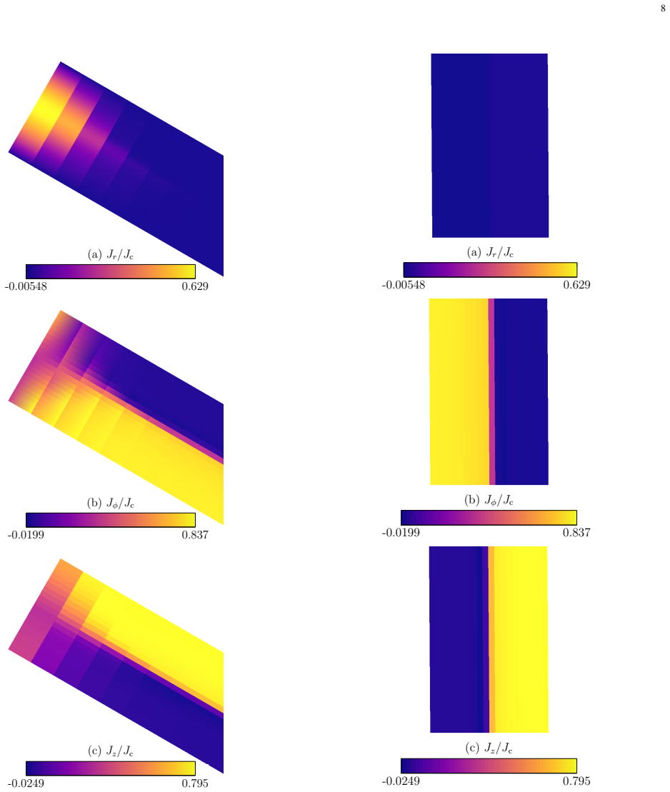
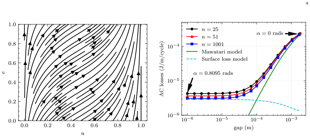
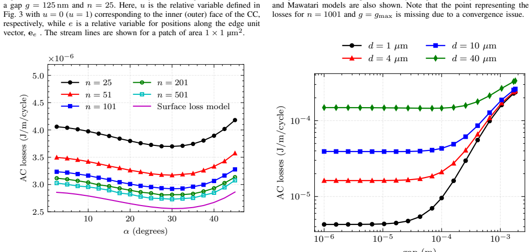
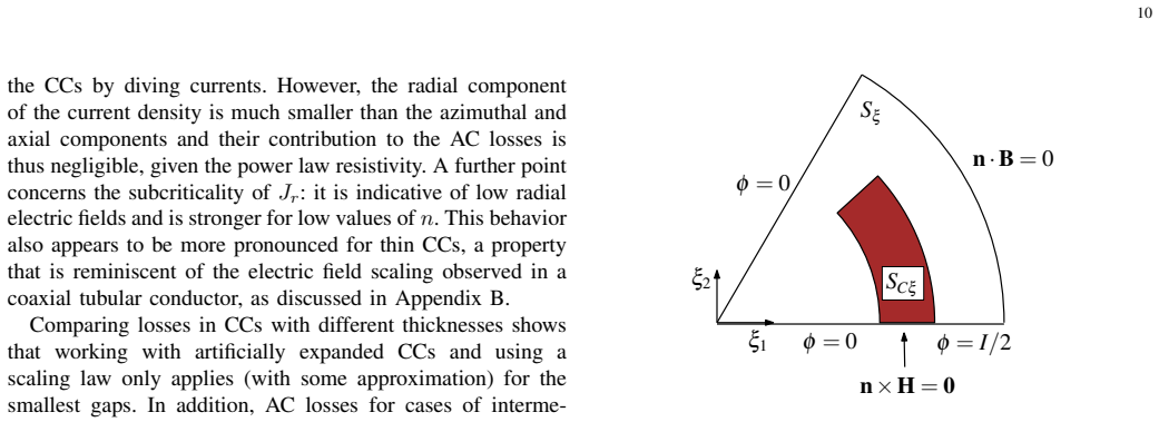
For a one-layer CORT cable the helical arrangement of the coated conductors produces the Garber current pattern in which current is predominantly axial on the outer face and azimuthal on the inner face of each conductor. An effective 2D model based on helical coordinates reproduces the resulting three-dimensional current and field distributions. This pattern modulates the surface losses associated with parallel-field penetration into the superconducting layers and the edge losses associated with perpendicular-field penetration near the gaps between conductors. The relative size of these contributions varies systematically with conductor thickness, pitch angle, and gap size.
What carries the argument
Effective 2D helical coordinate model that conforms to the cable structure and computes the detailed current flow and loss contributions from the Garber pattern.
If this is right
- The Garber pattern must be included in loss calculations rather than using straight-conductor simplifications.
- Surface losses and edge losses respond differently to changes in pitch angle and gap width.
- Optimal cable design requires balancing the geometrical parameters to minimize the sum of both loss types.
- Thicker conductors alter current penetration and therefore change the magnitude of each loss mechanism.
- The model provides a practical way to predict how loss shares shift with cable geometry.
Where Pith is reading between the lines
- Similar helical effects may appear in other wound superconducting devices and could be analyzed with the same coordinate approach.
- Direct experimental mapping of current on inner and outer faces of the conductors would test the model's predictions.
- Extending the model to multi-layer cables could reveal how interlayer coupling modifies the Garber pattern.
- Neglecting the pattern in existing designs may have led to underestimated AC losses in prototype CORT cables.
Load-bearing premise
The effective 2D helical coordinate model reproduces the full three-dimensional current and magnetic field distributions without systematic errors introduced by the coordinate transformation or neglected end effects.
What would settle it
Measuring the local current direction or magnetic field components on the inner versus outer faces of a coated conductor in an operating one-layer CORT cable and comparing the results to the model's predictions.
Figures
read the original abstract
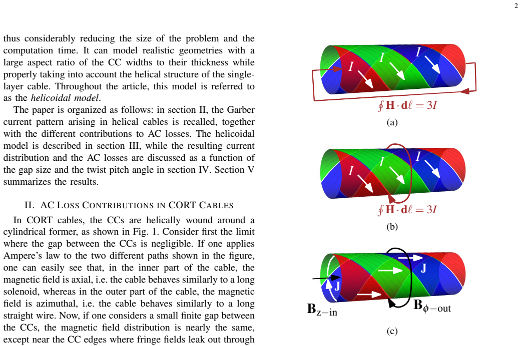
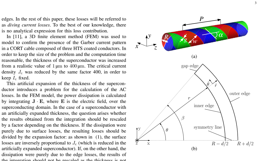
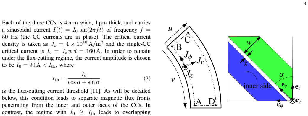
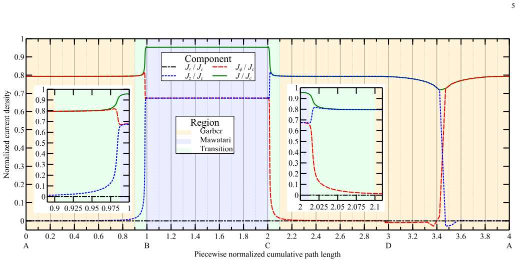
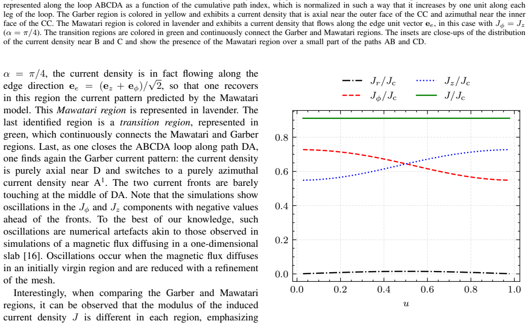
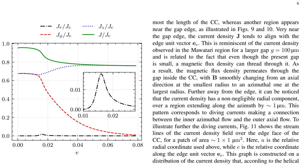
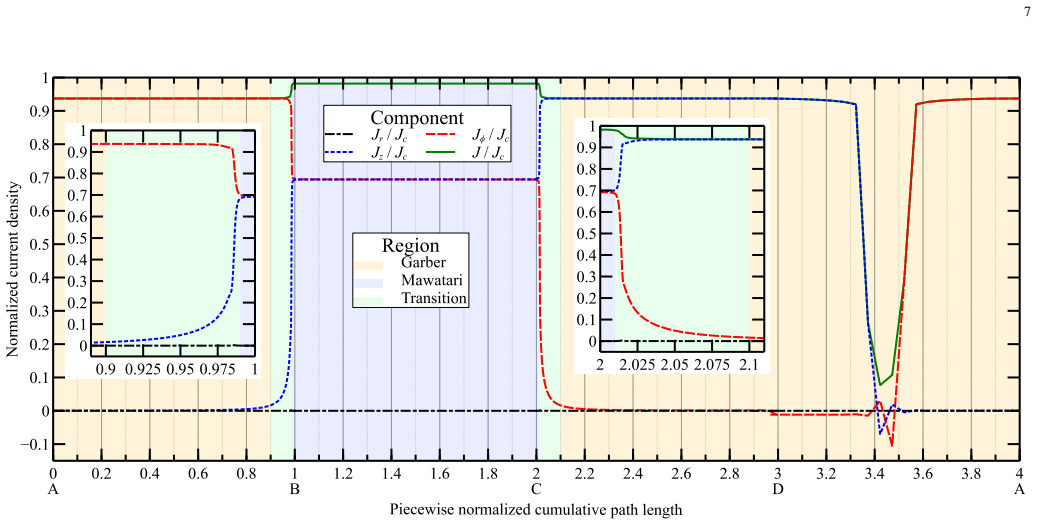
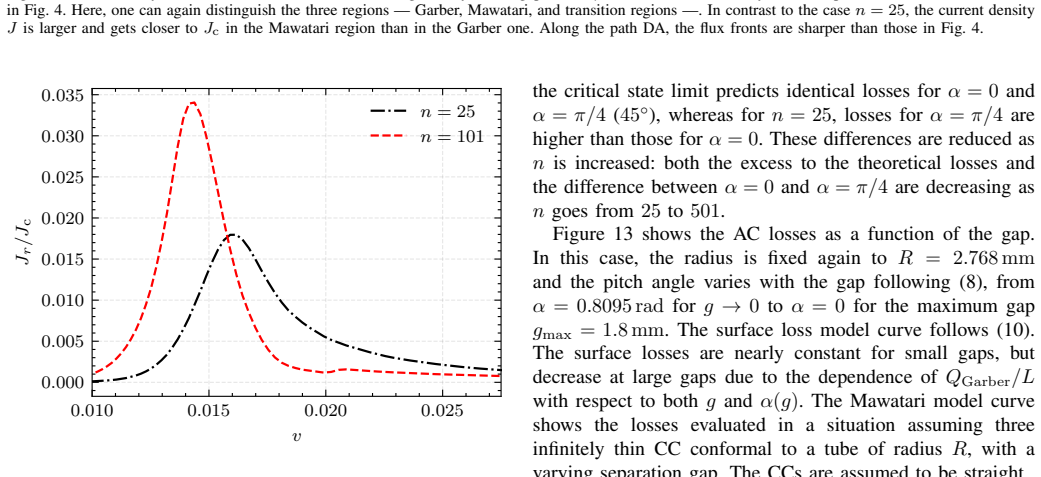
Conductor-on-round-tube (CORT) cables are a potential solution for carrying AC power in a small cross-section. Due to the geometry of the cable and the helical arrangement of the coated conductors (CC), the current follows a non-trivial pattern inside each CC. For instance, for the case of a single-layer cable, the current flow is mostly axial along the outer face of the CCs and mostly azimuthal along their inner face. Such a current distribution, known as the Garber current pattern, affects the transport AC losses. In numerical models, commonly adopted simplifications are either based on straight conductors or infinitely thin CCs. Such approaches neglect the Garber current pattern and thus misrepresent both the detailed current flow within the CC and the resulting 3D distribution of the fields. In this work, the detailed 3D current distribution in the CCs is investigated in a one-layer CORT cable, as a function of the cable geometrical parameters such as the conductor thickness, the pitch angle, and the gap between adjacent CCs. In particular, the impact of the Garber current pattern is studied on the two largest contributions to the AC losses, namely the surface losses (associated with the penetration of the component of the magnetic field parallel to the wide faces of the superconducting layer) and the edge losses (associated with the penetration of the perpendicular component of the magnetic field occurring in the vicinity of the gaps between the CCs). The detailed distribution of the currents in the CCs is examined and its relationship with the different AC loss mechanisms is established. This study is carried out by means of an effective 2D model that uses a system of coordinates conforming with the helical structure of the cable.
Editorial analysis
A structured set of objections, weighed in public.
Referee Report
Summary. The manuscript claims that an effective 2D model employing helical-conforming coordinates can be used to compute the detailed 3D current distribution inside the coated conductors of a one-layer CORT cable. It examines how the Garber current pattern (axial on the outer face, azimuthal on the inner face) varies with conductor thickness, pitch angle, and inter-conductor gap, and quantifies the resulting effects on the two dominant AC-loss channels: surface losses driven by the parallel field component and edge losses driven by the perpendicular field near the gaps.
Significance. If the effective 2D model is shown to reproduce the full 3D current and field distributions to acceptable accuracy, the work would supply a practical computational route for relating cable geometry to the dominant loss mechanisms and could guide geometric optimization of CORT cables for reduced AC losses.
major comments (1)
- [Abstract] Abstract: the central claim that the effective 2D helical model faithfully reproduces the Garber current pattern and the associated surface/edge loss contributions rests on an unvalidated premise. No comparison to full 3D simulations, no error metrics, and no experimental benchmarks are referenced, yet the reported parametric relationships between thickness, pitch, gap and the two loss channels are derived directly from this model.
Simulated Author's Rebuttal
We thank the referee for the constructive comments on our manuscript. Below we provide a point-by-point response to the major comment.
read point-by-point responses
-
Referee: [Abstract] Abstract: the central claim that the effective 2D helical model faithfully reproduces the Garber current pattern and the associated surface/edge loss contributions rests on an unvalidated premise. No comparison to full 3D simulations, no error metrics, and no experimental benchmarks are referenced, yet the reported parametric relationships between thickness, pitch, gap and the two loss channels are derived directly from this model.
Authors: The effective 2D model employs helical-conforming coordinates that exactly match the helical symmetry of the one-layer CORT cable. Under this symmetry the current and field distributions are invariant along the helical path, permitting an exact reduction of the 3D problem to a 2D problem with no approximation. The Garber pattern and the resulting surface/edge loss channels are therefore reproduced by construction; a separate full-3D simulation would be mathematically redundant. Error metrics between equivalent formulations are not required. The study is numerical and the scope does not include experimental benchmarks, which could be pursued separately. revision: no
Circularity Check
No circularity: numerical study applies standard helical-coordinate model without self-referential reductions
full rationale
The paper describes a numerical investigation of current distributions and AC losses in a one-layer CORT cable using an effective 2D model with helical-conforming coordinates. No equations, fitted parameters, or derivations are presented that reduce any claimed prediction or result to the inputs by construction. The Garber current pattern and loss contributions are examined parametrically as functions of thickness, pitch angle, and gap; the model itself is invoked as a computational tool based on electromagnetic principles rather than being defined in terms of the target outputs. No self-citations are load-bearing for uniqueness theorems or ansatzes, and the abstract provides no evidence of renaming known results or smuggling assumptions via prior work. The derivation chain is therefore self-contained against external benchmarks.
Axiom & Free-Parameter Ledger
Reference graph
Works this paper leans on
-
[1]
D. C. van der Laan, J. D. Weiss, and D. M. McRae, “Status of corc® cables and wires for use in high-field magnets and power systems a decade after their introduction,”Superconductor Science and Technology, vol. 32, no. 3, p. 033001, feb 2019. [Online]. Available: https://doi.org/10.1088/1361-6668/aafc82
-
[2]
Calculation and measurement of transport AC loss of ReBCO CORC cables for electric aircraft,
S. Otten, D. Ga ˇcnik, S. Br ¨uggenwirth, J. Leferink, M. Dhall ´e, H. H. J. ten Kate, S. A. D ¨onges, J. D. Weiss, K. Radcliff, D. C. van der Laan, J.- F. Rouquette, J. Rivenc, and E. Nilsson, “Calculation and measurement of transport AC loss of ReBCO CORC cables for electric aircraft,”IEEE Transactions on Applied Superconductivity, vol. 34, no. 3, p. 4703605,
-
[3]
Available: https://doi.org/10.1109/TASC.2024.3364120
[Online]. Available: https://doi.org/10.1109/TASC.2024.3364120
-
[4]
AmpaCity— Advanced superconducting medium voltage system for urban area power supply,
M. Stemmle, F. Merschel, M. Noe, and A. Hobl, “AmpaCity— Advanced superconducting medium voltage system for urban area power supply,”Proceedings of the IEEE PES TD Conf. Expo, pp. 1–5,
-
[5]
Available: https://doi.org/10.1109/TDC.2014.6863566
[Online]. Available: https://doi.org/10.1109/TDC.2014.6863566
-
[6]
Development of the Superlink HTS Cable System for Implementation in Munich,
D. Will ´en, M. Sed ´en, M. Pitzer, V . Roudriges-Zermeno, C. Thidemann, J. Kunert, D. D. Tjahjanto, C. Frohne, O. Holte, C. Wolff, W. Prusseit, C. Hintze, R. Bach, P. Mansheim, W. T. B. de Sousa, M. Noe, A. Alekseev, P. Michalek, and R. Prinz, “Development of the Superlink HTS Cable System for Implementation in Munich,”IEEE Transactions on Applied Superc...
arXiv 2025
-
[7]
J. D. Weiss, D. C. van der Laan, D. Hazelton, A. Knoll, G. Carota, D. Abraimov, A. Francis, M. A. Small, G. Bradford, and J. Jaroszynski, “Introduction of the next generation of CORC ® wires with engineering current density exceeding650A/mm 2 at12T based on SuperPower’s ReBCO tapes containing substrates of25µm thickness,” Superconductor Science and Techno...
-
[8]
Available: https://doi.org/10.1088/1361-6668/ab72c6
[Online]. Available: https://doi.org/10.1088/1361-6668/ab72c6
-
[9]
New Experimental Method for Investigating AC-losses in Concentric HTS Power Cables,
S. Elschner, E. Demencik, B. Douine, F. Grilli, A. Kudymow, M. Stemmle, S. Strauss, V . Zermeno, and W. Goldacker, “New Experimental Method for Investigating AC-losses in Concentric HTS Power Cables,”IEEE Transactions on Applied Superconductivity, vol. 25, no. 3, p. 5900105, 2015. [Online]. Available: https: //doi.org/10.1109/TASC.2014.2366373
-
[10]
An analysis of the transport losses measured on HTSC single-phase conductor prototypes,
G. Vellego and P. Metra, “An analysis of the transport losses measured on HTSC single-phase conductor prototypes,”Superconductor Science and Technology, vol. 8, pp. 476–483, 1995. [Online]. Available: https://doi.org/10.1088/0953-2048/8/6/014
-
[11]
Y . Mawatari, “Field distributions in curved superconducting tapes conforming to a cylinder carrying transport currents,”Physical Review B, vol. 80, p. 184508, 2009. [Online]. Available: https: //doi.org/10.1103/PhysRevB.80.184508
-
[12]
Design of double helix conductors for superconducting AC power transmission,
M. Garber, J. F. Bussiere, and G. H. Morgan, “Design of double helix conductors for superconducting AC power transmission,”MAGNETISM AND MAGNETIC MATERIALS — 1976: Proceedings of the First Joint MMM-Intermag Conference, vol. 34, pp. 84–87, 1976. [Online]. Available: https://doi.org/10.1063/1.2946170
-
[13]
Theory of AC loss in power transmission cables with second generation high temperature superconductor wires,
J. R. Clem and A. P. Malozemoff, “Theory of AC loss in power transmission cables with second generation high temperature superconductor wires,”Superconductor Science and Technology, vol. 23, p. 034014, 2010. [Online]. Available: https://doi.org/10.1088/ 0953-2048/23/3/034014
2010
-
[14]
The Garber Current Pattern: An Additional Contribution to AC Losses in Helical HTS Cables?
S. Elschner, A. Kudymow, N. Riva, and F. Grilli, “The Garber Current Pattern: An Additional Contribution to AC Losses in Helical HTS Cables?”IEEE Transactions on Applied Superconductivity, vol. 34, no. 3, p. 5902205, 2024. [Online]. Available: https: //doi.org/10.1109/TASC.2024.3356435
-
[15]
Helicoidal Transformation Method for Finite Element Models of Twisted Superconductors,
J. Dular, F. Henrotte, A. Nicolet, M. Wozniak, B. Vanderheyden, and C. Geuzaine, “Helicoidal Transformation Method for Finite Element Models of Twisted Superconductors,”IEEE Transactions on Applied Superconductivity, vol. 34, no. 7, p. 8200615, 2024. [Online]. Available: https://doi.org/10.1109/TASC.2024.3416524
-
[16]
Flux vortices and transport currents in type II superconductors,
A. M. Campbell and J. E. Evetts, “Flux vortices and transport currents in type II superconductors,”Advances in Physics, vol. 21, no. 90, pp. 199–428, 1972. [Online]. Available: https://doi.org/10.1080/ 00018737200101288
1972
-
[17]
Type-II-superconductor strip with current in a perpendicular magnetic field,
E. H. Brandt and M. Indenbom, “Type-II-superconductor strip with current in a perpendicular magnetic field,”Physical Review B, vol. 48, no. 17, pp. 12 893–12 906, 1993. [Online]. Available: https://doi.org/10.1103/PhysRevB.48.12893
-
[18]
Fast numerical computation of current distribution and AC losses in helically wound thin tape conductors: Single-layer coaxial arrangement,
M. Siahrang, F. Sirois, D. N. Nguyen, S. Babic, and S. P. Ashworth, “Fast numerical computation of current distribution and AC losses in helically wound thin tape conductors: Single-layer coaxial arrangement,” IEEE Transactions on Applied Superconductivity, vol. 20, no. 6, pp. 2381–2389, 2010
2010
-
[19]
Finite-element for- mulations for systems with high-temperature superconductors,
J. Dular, C. Geuzaine, and B. Vanderheyden, “Finite-element for- mulations for systems with high-temperature superconductors,”IEEE Transactions on Applied Superconductivity, vol. 30, no. 3, pp. 1–13, 2020
2020
-
[20]
Understanding AC losses in CORC cables of YBCO superconducting tapes by numerical simulations,
L. N. Nguyen, N. Shields, S. Ashworth, and D. N. Nguyen, “Understanding AC losses in CORC cables of YBCO superconducting tapes by numerical simulations,”Journal of Applied Physics, vol. 134, no. 14, p. 143903, 10 2023. [Online]. Available: https://doi.org/10.1063/5.0162439
-
[21]
Reduction of AC losses in HTS power transmission cables made of coated conductors by overlapping the tapes,
M. Siahrang and F. Sirois, “Reduction of AC losses in HTS power transmission cables made of coated conductors by overlapping the tapes,”Superconductor Science and Technology, vol. 24, no. 1, p. 015004, dec 2010. [Online]. Available: https://doi.org/10.1088/ 0953-2048/24/1/015004
2010
-
[22]
P. Vanderbemden, Z. Hong, T. A. Coombs, S. Denis, M. Ausloos, J. Schwartz, I. B. Rutel, N. Hari Babu, D. A. Cardwell, and A. M. Campbell, “Behavior of bulk high-temperature superconductors of finite thickness subjected to crossed magnetic fields: Experiment and model,” Phys. Rev. B, vol. 75, p. 174515, May 2007. [Online]. Available: https://link.aps.org/d...
-
[23]
Carr Jr.,AC Loss and Macroscopic Theory of Superconductors (2nd ed.)
W. Carr Jr.,AC Loss and Macroscopic Theory of Superconductors (2nd ed.). CRC Press, 2001
2001
discussion (0)
Sign in with ORCID, Apple, or X to comment. Anyone can read and Pith papers without signing in.