Thermal and electromechanical response of ultra-thin carbon-strip polarimeter targets in relativistic bunched beams
Pith reviewed 2026-06-30 08:06 UTC · model grok-4.3
The pith
A coupled model of beam heating, motion, forces, and RF effects shows carbon-strip targets match RHIC lifetimes but face viability limits at EIC.
A machine-rendered reading of the paper's core claim, the machinery that carries it, and where it could break.
Core claim
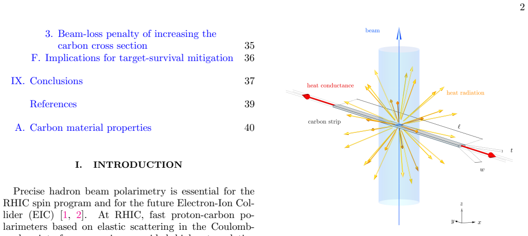
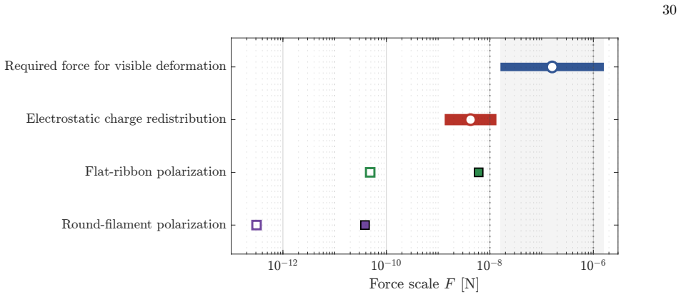
We develop a coupled response model that combines beam-target overlap, secondary-electron escape, retained heat, target motion, transient heat transport, RF-induced strip-end heating, beam-induced forces, resistance changes, and slack-strip deformation. RHIC target observations constrain the relevant motion, force, and nonlocal-heating scales and show that target survival depends on both beam-center heating and electromagnetic boundary conditions near the strip ends. Applying the model to Booster, AGS, RHIC, and EIC proton and 3He cases shows that the RHIC proton lifetime scale is reproduced at the order-of-magnitude level, while the RHIC target-holder fin results require the additional RF/e
What carries the argument
The coupled response model that integrates beam-target overlap, secondary-electron escape, retained heat, target motion, transient heat transport, RF-induced strip-end heating, beam-induced forces, resistance changes, and slack-strip deformation.
If this is right
- RHIC proton lifetime scale is reproduced at the order-of-magnitude level by the model.
- RHIC target-holder fin results require the additional RF/end-heating mechanism.
- EIC proton flattop operation may remain viable only with reduced dwell time, sufficient detector acceptance, and suppression of RF-induced end heating.
- For cooled-emittance 3He, the sublimation-loss scale exceeds a straightforward RHIC-like carbon-strip extrapolation.
- Conventional carbon strips are unlikely to remain viable for the most demanding EIC light-ion cases without major changes in target motion, technology, or diagnostic concept.
Where Pith is reading between the lines
- The model framework could be reused to assess thin-target survival in other high-intensity hadron machines beyond those explicitly calculated.
- Suppression of RF end heating would require either altered strip mounting geometry or active cooling at the holder fins.
- If dwell time cannot be reduced enough, polarimetry at EIC light-ion energies may need to move to non-carbon target materials or entirely different diagnostic methods.
- Varying beam intensity or bunch structure in controlled RHIC tests could further tighten the motion and force parameters used in the extrapolation.
Load-bearing premise
RHIC target observations are sufficient to fix the free parameters for motion, force, and nonlocal heating so that the model can be extrapolated to EIC conditions.
What would settle it
Direct measurement of carbon-strip lifetime or end-to-center temperature profile in EIC proton flattop conditions with controlled RF suppression would confirm or refute the predicted viability boundary.
Figures
read the original abstract
Thin carbon-strip targets provide fast relative hadron beam polarimetry, but their response in intense relativistic bunched beams is not governed by local stopping-power heating alone. We develop a coupled response model that combines beam-target overlap, secondary-electron escape, retained heat, target motion, transient heat transport, RF-induced strip-end heating, beam-induced forces, resistance changes, and slack-strip deformation. RHIC target observations constrain the relevant motion, force, and nonlocal-heating scales and show that target survival depends on both beam-center heating and electromagnetic boundary conditions near the strip ends. Applying the model to Booster, AGS, RHIC, and EIC proton and $^{3}\mathrm{He}$ cases shows that the RHIC proton lifetime scale is reproduced at the order-of-magnitude level, while the RHIC target-holder fin results require the additional RF/end-heating mechanism. For EIC proton flattop operation, carbon-strip polarimetry may remain viable only with reduced dwell time, sufficient detector acceptance, and suppression of RF-induced end heating. For cooled-emittance $^{3}\mathrm{He}$, the calculated sublimation-loss scale is far beyond a straightforward RHIC-like carbon-strip extrapolation. Conventional carbon strips are therefore unlikely to remain viable for the most demanding EIC light-ion cases without major changes in target motion, target technology, or diagnostic concept.
Editorial analysis
A structured set of objections, weighed in public.
Referee Report
Summary. The manuscript develops a multi-physics coupled model for the response of ultra-thin carbon-strip polarimeter targets to relativistic bunched beams. The model incorporates beam-target overlap, secondary-electron escape, retained heat, target motion, transient heat transport, RF-induced end heating, beam-induced forces, resistance changes, and slack deformation. RHIC target observations are used to constrain motion, force, and nonlocal-heating scales. The calibrated model is applied to Booster, AGS, RHIC, and EIC proton and 3He cases, reproducing RHIC proton lifetime at order-of-magnitude level (with RF/end-heating required to match fin results) and concluding that EIC proton flattop operation requires reduced dwell time, detector acceptance, and RF suppression while cooled-emittance 3He cases exceed straightforward RHIC-like extrapolation.
Significance. If the central calibration and extrapolation hold, the work addresses a practical limit on carbon-strip polarimetry for high-intensity hadron machines and supplies quantitative guidance on target viability and required design changes for the EIC. The coupling of thermal, mechanical, and electromagnetic effects across multiple accelerator stages is a positive feature.
major comments (2)
- [Abstract and §4 (RHIC calibration)] The abstract states that RHIC observations constrain the motion, force, and nonlocal-heating scales and that the model reproduces RHIC proton lifetime at order-of-magnitude level, yet no quantitative comparison (error bars, χ^{2}, or data tables) is referenced; without this, the claim that the calibration is sufficient to fix the free parameters for EIC extrapolation remains load-bearing but unverified.
- [§5 (EIC application)] The EIC viability conclusions (reduced dwell time plus RF suppression for protons; non-viability for cooled 3He) rest on the assumption that the RHIC-constrained scales remain dominant at EIC intensities and emittances; the manuscript does not present a sensitivity study varying beam-induced force or RF boundary conditions to test degeneracy or missing physics.
minor comments (2)
- [Model description] Notation for the resistance change and slack deformation terms should be defined explicitly on first use rather than introduced inline.
- [Figures 4-6] Figure captions for the RHIC lifetime and fin-heating comparisons should include the specific beam parameters and the quantitative metric used for the order-of-magnitude statement.
Simulated Author's Rebuttal
We thank the referee for the careful and constructive review. We address the two major comments point by point below, indicating the revisions that will be incorporated.
read point-by-point responses
-
Referee: [Abstract and §4 (RHIC calibration)] The abstract states that RHIC observations constrain the motion, force, and nonlocal-heating scales and that the model reproduces RHIC proton lifetime at order-of-magnitude level, yet no quantitative comparison (error bars, χ^{2}, or data tables) is referenced; without this, the claim that the calibration is sufficient to fix the free parameters for EIC extrapolation remains load-bearing but unverified.
Authors: We agree that the calibration claim would be strengthened by explicit quantitative metrics. The manuscript currently states only that the RHIC proton lifetime is reproduced at the order-of-magnitude level after constraining the motion, force, and nonlocal-heating scales from observations. In the revised manuscript we will add a table in §4 that tabulates the observed versus modeled lifetimes for the RHIC proton cases, together with the estimated uncertainties arising from the input scales. This addition will make the calibration more transparent and directly support the EIC extrapolations. revision: yes
-
Referee: [§5 (EIC application)] The EIC viability conclusions (reduced dwell time plus RF suppression for protons; non-viability for cooled 3He) rest on the assumption that the RHIC-constrained scales remain dominant at EIC intensities and emittances; the manuscript does not present a sensitivity study varying beam-induced force or RF boundary conditions to test degeneracy or missing physics.
Authors: The referee is correct that no explicit sensitivity study is presented. The EIC conclusions rely on the RHIC-derived scales remaining the leading effects. To address possible degeneracies, the revised §5 will include a short sensitivity analysis in which the beam-induced force and RF end-heating amplitudes are varied by a factor of two around the RHIC-calibrated values; the resulting changes to the predicted EIC lifetimes will be shown. This limited study will test the robustness of the viability statements while preserving the central conclusions of the work. revision: yes
Circularity Check
No significant circularity; model calibrated on RHIC data then extrapolated
full rationale
The paper develops a coupled physical model (beam overlap, heat transport, forces, RF heating, deformation) and states that RHIC observations constrain its free scales for motion/force/nonlocal heating. It then applies the same model to other accelerators including EIC. This is standard calibration-plus-extrapolation with independent physical content; the EIC regime differs in intensity and emittance, and no step reduces by construction to the RHIC inputs via definition, renaming, or self-citation chain. No equations or uniqueness claims are shown to collapse to the fit itself.
Axiom & Free-Parameter Ledger
free parameters (1)
- motion, force, and nonlocal-heating scales
Reference graph
Works this paper leans on
-
[1]
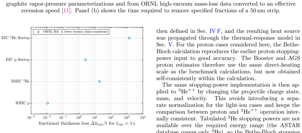
For the RHIC p reference case, Fig
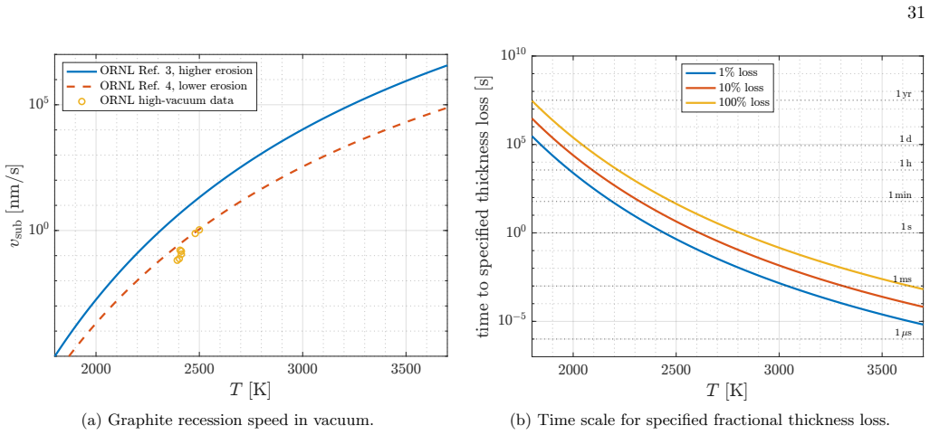
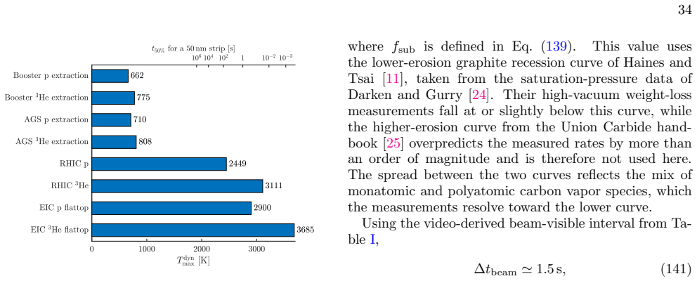
RHIC lifetime scale The RHIC p calculation provides an empirical scale check for the present model. For the RHIC p reference case, Fig. 16 gives the one-second fractional sublimation loss (fsub)1 s ≃ 0.011, (140) where fsub is defined in Eq. (139). This value uses the lower-erosion graphite recession curve of Haines and Tsai [11], taken from the saturatio...
2013
-
[2]
For T dyn max ≃ 2900 K, (146) Fig
EIC extrapolation Applying the same conservative cycle estimate to the EIC p flattop cooled-emittance case gives a much more restrictive result. For T dyn max ≃ 2900 K, (146) Fig. 16 gives, on the lower-erosion curve, (fsub)1 s ≃ 2.6. (147) For a RHIC-like full cycle with ∆tcycle ≃ 3 s, (148) this corresponds to (fsub)cycle ≃ 7.7. (149) Thus, already on t...
-
[3]
Under the present assumptions, this carbon-strip operating point is likely not viable with RHIC-like scan times
The corresponding peak temperature, 3685 K, now lies about 35 K above the adopted graphite sublimation reference Tsub = 3650 K. Under the present assumptions, this carbon-strip operating point is likely not viable with RHIC-like scan times. It would require a major reduc- tion of dwell time near the beam core, a reduction of the peak heat source, a differ...
-
[4]
One possi- ble approach would be to increase the amount of carbon in the target
Beam-loss penalty of increasing the carbon cross section The preceding comparison shows that the EIC pro- ton and especially the EIC 3He cooled-emittance flattop cases would require much longer sublimation-loss times than obtained with the nominal carbon strip. One possi- ble approach would be to increase the amount of carbon in the target. This option, h...
-
[5]
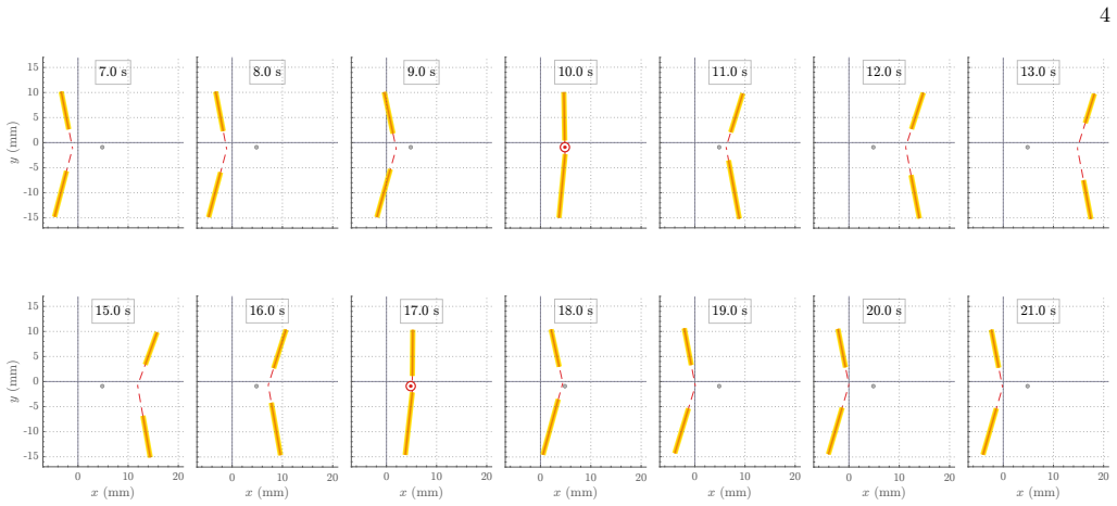
Faster motion through the beam core does not re- duce the instantaneous peak heat source, but it reduces the exposure time and therefore the frac- tional sublimation loss fsub
Reduce target dwell time. Faster motion through the beam core does not re- duce the instantaneous peak heat source, but it reduces the exposure time and therefore the frac- tional sublimation loss fsub. To first approxima- tion, fsub ∝ 1 vt . (163) The video analysis in Table I gives a near-beam speed scale of vt ≃ 4 mm s−1. The EIC p flat- top cooled-emi...
-
[6]
Shorter dwell time reduces the number of detected events per pass
Compensate reduced dwell time with detec- tor acceptance. Shorter dwell time reduces the number of detected events per pass. Since fast beam-polarization and beam-profile feedback re- main required for machine operation, this loss must be compensated by larger detector area, larger an- gular acceptance, improved readout efficiency, or a modified scan strategy
-
[7]
The peak particle flux and projected beam size at the target enter directly into 37 TABLE XII: Beam-removal estimate for nominal and survival-equivalent carbon targets
Change beam optics. The peak particle flux and projected beam size at the target enter directly into 37 TABLE XII: Beam-removal estimate for nominal and survival-equivalent carbon targets. The survival-equivalent EIC entries have their carbon cross section scaled up by the factor FA so that the target provides a comparable number of measurements to the RH...
-
[8]
2 .1 × 102 250–300 0 .44–0.52% 1 .3–1.6% RHIC 3He, survival-equiv
[mb] [1] [1] RHIC p, nominal strip 1 250–300 (2 .1–2.5) × 10−5 (6.3–7.5) × 10−5 EIC p flattop, survival-equiv. 2 .1 × 102 250–300 0 .44–0.52% 1 .3–1.6% RHIC 3He, survival-equiv. 2 .0 × 103 1000 15 .3% 38 .5% EIC 3He flattop, survival-equiv. 1 .7 × 105 1000 ≃ 100% ≃ 100% the thermal source. Larger beam size, lower peak flux, reduced bunch intensity, or dif...
-
[9]
The RHIC target-survival study [6] shows that modifying the electromagnetic environment near the target ends can strongly improve lifetime
Suppress RF-induced end heating. The RHIC target-survival study [6] shows that modifying the electromagnetic environment near the target ends can strongly improve lifetime. For EIC operation, alumina holders or other low-conductivity holder concepts will suppress RF-induced end heating and target-end failures, as discussed in Sec. VI D. This addresses end...
-
[10]
For the most severe EIC cases, im- proved carbon-strip operation may no longer be sufficient
Develop alternative target or diagnostic technologies. For the most severe EIC cases, im- proved carbon-strip operation may no longer be sufficient. The EIC p flattop cooled-emittance case may still be extended through faster scans, larger detector acceptance, and improved electromagnetic boundary conditions, but only as an interim mea- sure rather than a...
-
[11]
Willeke and J
F. Willeke and J. Beebe-Wang, Electron Ion Collider Conceptual Design Report 2021 , Tech. Rep. (Brookhaven National Lab. (BNL), Upton, NY (United States); Thomas Jefferson National Accelerator Facility (TJ- NAF), Newport News, VA (United States), 2021)
2021
-
[12]
Abdul Khalek, A
R. Abdul Khalek, A. Accardi, J. Adam, D. Adamiak, W. Akers, M. Albaladejo, A. Al-bataineh, M. Alex- eev, F. Ameli, P. Antonioli, N. Armesto, W. Arm- strong, M. Arratia, J. Arrington, A. Asaturyan, M. Asai, E. Aschenauer, S. Aune, H. Avagyan, C. Ayerbe Gayoso, B. Azmoun, A. Bacchetta, M. Baker, F. Bar- bosa, L. Barion, K. Barish, P. Barry, M. Battaglieri, ...
2022
-
[13]
Bravar, in AIP Conference Proceedings , Vol
A. Bravar, in AIP Conference Proceedings , Vol. 792 (2005) pp. 1039–1042
2005
-
[14]
W. R. Lozowski, D. Steski, H. Huang, and C. Naylor, Nuclear Instruments and Methods in Physics Research Section A 590, 157 (2008)
2008
-
[15]
D. B. Steski, L. Sukhanova, A. Zelenski, and W. B. Christie, Journal of Radioanalytical and Nuclear Chem- istry 299, 1035 (2014)
2014
-
[16]
D. B. Steski, H. Huang, J. Kewisch, L. Sukhanova, and A. Zelenski, in Proceedings of the 28th World Conference of the International Nuclear Target Development Society , AIP Conference Proceedings, Vol. 1962 (AIP Publishing,
1962
-
[17]
Fischer and A
W. Fischer and A. Bazilevsky, Physical Review Special Topics - Accelerators and Beams 15, 041001 (2012)
2012
-
[18]
Rathmann, A
F. Rathmann, A. Nass, K. O. Eyser, V. Shmakova, E. C. Aschenauer, G. Atoian, A. Cannavo, X. Chu, K. Hock, H. Huang, H. Lovelace, G. Mahler, N. N. Nikolaev, J. Ritter, G. Robert-Demolaize, V. Schoefer, P. Shanmu- ganathan, E. Shulga, H. Soltner, and Z. Zhang, Physical Review Accelerators and Beams 29, 021001 (2026)
2026
-
[19]
G. Atoian, N. Buttimore, G. Ciullo, I. Cloet, M. Con- talbrigo, J. Datta, A. Deshpande, S. Dutta, O. Eyser, M. Farooq, et al. 10.48550/arXiv.2510.10794 (2025), sub- mitted to Phys. Rev. C, arXiv:2510.10794 [nucl-ex]
-
[20]
Brewer, P
L. Brewer, P. W. Gilles, and F. A. Jenkins, The Journal of Chemical Physics 16, 797 (1948)
1948
-
[21]
J. R. Haines and C. C. Tsai, Graphite Sublimation Tests for the Muon Collider/Neutrino Factory Target Development Program , Tech. Rep. ORNL/TM-2002/27 (Oak Ridge National Laboratory, Oak Ridge, TN, USA,
2002
-
[22]
DOE contract DE-AC05-00OR22725
u.S. DOE contract DE-AC05-00OR22725. Avail- able at https://info.ornl.gov/sites/publications/ Files/Pub57715.pdf
-
[23]
N. A. Tahir, V. Kim, B. Schlitt, W. Barth, L. Groening, I. V. Lomonosov, A. R. Piriz, T. St¨ ohlker, and H. Vor- mann, Phys. Rev. ST Accel. Beams 17, 041003 (2014)
2014
-
[24]
Lee, Accelerator Physics (World Scientific, 2004)
S. Lee, Accelerator Physics (World Scientific, 2004)
2004
-
[25]
Becker, Theory of Heat (Springer-Verlag, 1985)
R. Becker, Theory of Heat (Springer-Verlag, 1985)
1985
-
[26]
D. W. Hahn and M. N. ¨Ozisik, Heat Conduction , 3rd ed. (Wiley, 2012)
2012
-
[27]
J. D. Jackson, Classical Electrodynamics, 3rd ed. (Wiley, New York, 1999)
1999
-
[28]
L. D. Landau, E. M. Lifshitz, and L. P. Pitaevskii, Elec- trodynamics of Continuous Media , 2nd ed. (Pergamon Press, Oxford, 1984)
1984
-
[29]
Steski, RHIC and AGS CNI carbon target parameters (2026), private communication
D. Steski, RHIC and AGS CNI carbon target parameters (2026), private communication
2026
-
[30]
M. E. M. Stewart, A Historical Review of Cermet Fuel Development and the Engine Performance Implications , NASA Technical Memorandum NASA/TM-2015-218987 (NASA Glenn Research Center, Cleveland, OH, 2015) nASA Document ID 20150002852
2015
-
[31]
Abrahamson, Carbon 12, 111 (1974)
J. Abrahamson, Carbon 12, 111 (1974)
1974
-
[32]
J. F. O’Hanlon, A User’s Guide to Vacuum Technology , 3rd ed. (John Wiley & Sons, Hoboken, NJ, 2003)
2003
-
[33]
W. R. Leo, Techniques for Nuclear and Particle Physics Experiments: A How-to Approach , 2nd ed. (Springer, Berlin, 1994)
1994
-
[34]
Shmakova, E
V. Shmakova, E. Shulga, X. Chu, J. Datta, K. O. Eyser, W. Fischer, K. Hernandez, K. Hock, H. Huang, G. Mahler, P. MohanMurthy, R. Porqueddu, D. Ra- paria, V. Schoefer, P. Shanmuganathan, A. Verderosa, N. Wuerfel, Z. Zhang, and F. Rathmann, An absolute recoil-carbon polarimeter for polarized light-ions at the BNL Booster, Tech. Rep. (Brookhaven National La...
2026
-
[35]
L. S. Darken and R. W. Gurry, Physical Chemistry of Metals, Metallurgy and Metallurgical Engineering Series (McGraw-Hill, New York, NY, USA, 1953) oCLC 544719. Catalog record: https://search.worldcat.org/oclc/ 544719
1953
-
[36]
Union Carbide Corporation, Carbon Products Division, The Industrial Graphite Engineering Handbook (Union Carbide Corporation, New York, NY, USA, 1969) vapor-pressure data tables reproduced in Ref. [11]. Scanned copy: https://nucleus.iaea.org/sites/ graphiteknowledgebase/Meetings2/Old%20Meetings/ 2017/Background%20Info/GraphiteHandbook.pdf
1969
-
[37]
F. Abusaif et al. (CPEDM), Storage ring to search for electric dipole moments of charged particles: Feasibil- ity study , CERN Yellow Reports: Monographs, Vol. 3 (CERN, Geneva, 2021) arXiv:1912.07881 [hep-ex]
-
[38]
Khoukaz, in Proceedings of the 8th International Con- ference on Nuclear Physics at Storage Rings (STORI11) , Proceedings of Science, Vol
A. Khoukaz, in Proceedings of the 8th International Con- ference on Nuclear Physics at Storage Rings (STORI11) , Proceedings of Science, Vol. STORI11 (2011) p. 036
2011
-
[39]
Pyszniak et al
A. Pyszniak et al. , in EPJ Web of Conferences , Vol. 66 (2014) p. 11031
2014
-
[40]
M. J. Berger, J. S. Coursey, M. A. Zucker, and J. Chang, PSTAR: Stopping power and range tables for pro- tons, National Institute of Standards and Technology, Gaithersburg, MD (2025), [Online; accessed 2-April- 2025]
2025
-
[41]
Robertson, Materials Science and Engineering: R: Re- ports 37, 129 (2002)
J. Robertson, Materials Science and Engineering: R: Re- ports 37, 129 (2002)
2002
-
[42]
C. A. Taylor, M. F. Wayne, and W. K. S. Chiu, Carbon 41, 1867 (2003)
2003
-
[43]
O. L. Blakslee, D. G. Proctor, E. J. Seldin, G. B. Spence, and T. Weng, Journal of Applied Physics41, 3373 (1970)
1970
-
[44]
S. Cho, I. Chasiotis, T. A. Friedmann, and J. P. Sullivan, Journal of Micromechanics and Microengineering 15, 728 (2005)
2005
-
[45]
Huff, Micromachines 13, 2084 (2022)
M. Huff, Micromachines 13, 2084 (2022). Appendix A: Carbon material properties The carbon-strip response depends on thermal, elec- trical, and mechanical properties. These properties are strongly process dependent. Amorphous carbon lacks long-range crystalline order, while sputtered and evap- orated carbon films are produced by physical vapor de- position...
2084
discussion (0)
Sign in with ORCID, Apple, or X to comment. Anyone can read and Pith papers without signing in.