Wavelet-Optimized Pseudo-3D Accelerated Diffusion Model for Truncated Computed Laminography
Pith reviewed 2026-07-01 06:02 UTC · model grok-4.3
The pith
CL-DM uses a pseudo-3D diffusion model with wavelet regularization to reconstruct truncated laminography data beyond the field of view while enforcing consistency via MBIR.
A machine-rendered reading of the paper's core claim, the machinery that carries it, and where it could break.
Core claim
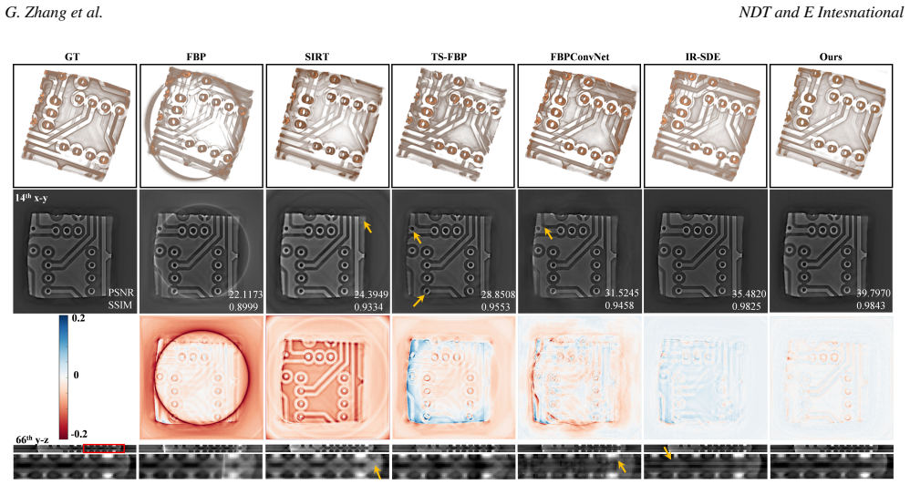
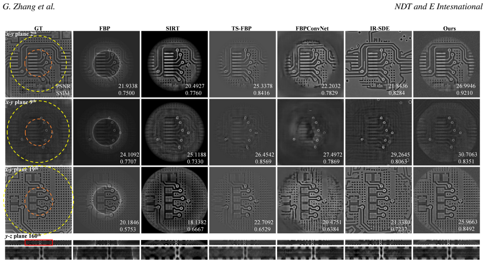
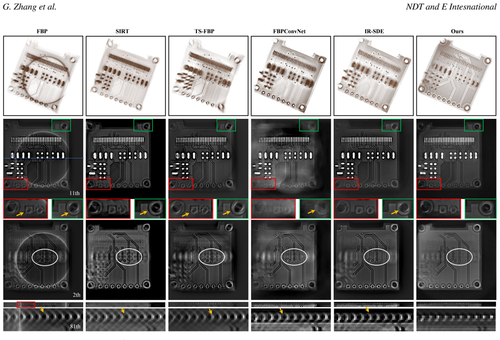
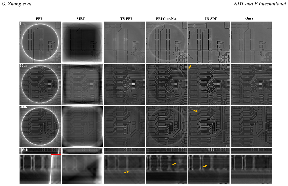
By extending the reconstruction target into the data-incomplete region and combining 2D diffusion slice aggregation with 3D MBIR for strict consistency plus wavelet regularization along z, the CL-DM method removes truncation artifacts and recovers high-fidelity continuous 3D structures in both simulated and real computed laminography experiments.
What carries the argument
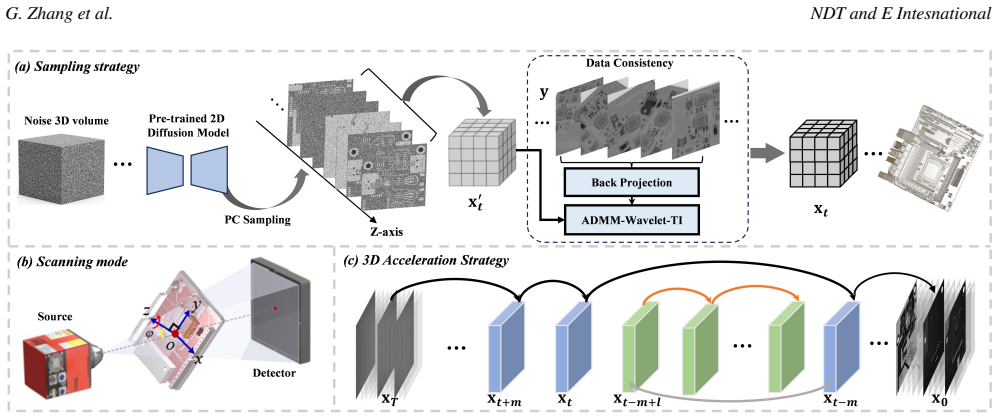
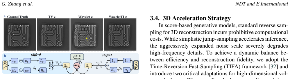
The CL-DM architecture: a 2D diffusion model for slice-wise generation, tied to 3D MBIR for data consistency, with wavelet regularization in the z-direction, translation-invariant mechanism, and low-frequency preservation to maintain inter-slice continuity.
If this is right
- Effective imaging range expands because reconstruction now covers the data-incomplete region instead of stopping at the FOV boundary.
- Data consistency with measured projections remains strict because the 3D MBIR step is retained at each iteration.
- Inter-slice continuity improves through wavelet regularization combined with translation-invariant and low-frequency preservation.
- Inference time drops substantially due to the introduced 3D fast sampling architecture.
- Truncation artifacts are reduced and high-fidelity continuous 3D structures are restored, as shown in both simulations and real experiments.
Where Pith is reading between the lines
- The same pseudo-3D pattern of 2D diffusion plus 3D consistency enforcement could be tested on other truncated tomography modalities such as limited-angle CT.
- Shorter scan times for large flat objects become feasible if the method reliably recovers the missing region without extra projections.
- Industrial nondestructive testing workflows could shift from 2D slice-by-slice networks to this hybrid diffusion-MBIR form if the continuity guarantees hold across varied truncation geometries.
- Further experiments that deliberately vary the size of the data-incomplete region would reveal the practical limits of the wavelet-regularization step.
Load-bearing premise
Extending reconstruction into the data-incomplete region plus wavelet regularization will keep data consistency and slice continuity without creating new artifacts that the MBIR step cannot correct.
What would settle it
Reconstructed volumes in the data-incomplete region that violate the original projection measurements or show visible slice-to-slice discontinuities after the full pipeline would falsify the central claim.
Figures
read the original abstract
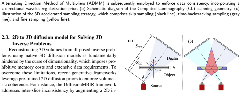
Computed Laminography (CL) is a key technology for the nondestructive testing of large plate-shaped objects. However, field-of-view (FOV) limitations inevitably lead to truncation of projected data, an ill-posed inverse problem that causes severe reconstruction artifacts. Existing deep learning methods typically rely on 2D architectures that lack rigorous data consistency constraints. Furthermore, they conventionally confine artifact removal strictly to the FOV, discarding potentially recoverable information outside it. To overcome these limitations, we first introduce a comprehensive CL FOV analysis, categorizing the space into data-complete, data-incomplete, and data-free regions. By extending our reconstruction target to encompass the data-incomplete region, we significantly expand the effective imaging range and enhance scanning efficiency. To achieve this, we propose a novel wavelet-optimized pseudo-3D accelerated diffusion model for CL truncation reconstruction (CL-DM). Our method utilizes a standard 2D diffusion model for slice aggregation, combined with a 3D model-based iterative reconstruction (MBIR) method to ensure strict data consistency. To mitigate inter-slice discontinuities, we introduce wavelet regularization along the z-direction, paired with a translation-invariant (TI) mechanism and a low-frequency preservation strategy. Finally, we introduce a 3D fast sampling architecture, significantly accelerating inference speed. Extensive simulations and real-world experiments demonstrate that CL-DM is superior in effectively eliminating truncation artifacts and restoring high-fidelity, continuous 3D structures.
Editorial analysis
A structured set of objections, weighed in public.
Referee Report
Summary. The manuscript proposes CL-DM, a wavelet-optimized pseudo-3D accelerated diffusion model for truncated computed laminography reconstruction. It first provides a FOV analysis dividing space into data-complete, data-incomplete, and data-free regions, then extends reconstruction into the data-incomplete region. The method uses a standard 2D diffusion model for slice aggregation, integrates 3D MBIR to enforce data consistency, applies wavelet regularization along z with a translation-invariant mechanism and low-frequency preservation to ensure inter-slice continuity, and introduces a 3D fast sampling architecture for acceleration. Extensive simulations and real experiments are stated to demonstrate superiority in artifact elimination and restoration of high-fidelity continuous 3D structures.
Significance. If the data-consistency integration and performance claims are substantiated, the work could meaningfully advance nondestructive testing of large plate-like objects by expanding the effective imaging range beyond conventional FOV limits and accelerating inference, with the pseudo-3D diffusion-plus-MBIR-plus-wavelet combination offering a practical route for ill-posed tomographic problems.
major comments (2)
- [Abstract] Abstract: the assertion that 'extensive simulations and real-world experiments demonstrate that CL-DM is superior' is unsupported by any quantitative metrics (PSNR, SSIM, etc.), baseline comparisons, error bars, or details on data exclusion/hyperparameter selection, which directly undermines verification of the central superiority claim.
- [Method integration] Method integration (described in the abstract and likely §3): the claim that 3D MBIR enforces strict data consistency after 2D diffusion outputs and z-direction wavelet regularization lacks explicit equations, pseudocode, or algorithmic steps showing how consistency violations in the data-incomplete region are detected and corrected; this is load-bearing for the data-fidelity guarantee.
minor comments (1)
- [Introduction] The FOV categorization into data-complete/incomplete/free regions is clearly motivated and could be highlighted earlier as a standalone contribution.
Simulated Author's Rebuttal
We thank the referee for the constructive feedback. We address each major comment below and outline the planned revisions.
read point-by-point responses
-
Referee: [Abstract] Abstract: the assertion that 'extensive simulations and real-world experiments demonstrate that CL-DM is superior' is unsupported by any quantitative metrics (PSNR, SSIM, etc.), baseline comparisons, error bars, or details on data exclusion/hyperparameter selection, which directly undermines verification of the central superiority claim.
Authors: We agree that the abstract would be strengthened by including key quantitative results. The manuscript body reports PSNR/SSIM comparisons, baseline methods, error bars, and experimental protocols, but these are not summarized in the abstract. We will revise the abstract to incorporate representative metrics (e.g., average PSNR gains over baselines) and a brief note on the evaluation protocol. This directly addresses the verifiability concern. revision: yes
-
Referee: [Method integration] Method integration (described in the abstract and likely §3): the claim that 3D MBIR enforces strict data consistency after 2D diffusion outputs and z-direction wavelet regularization lacks explicit equations, pseudocode, or algorithmic steps showing how consistency violations in the data-incomplete region are detected and corrected; this is load-bearing for the data-fidelity guarantee.
Authors: We acknowledge that the current description of the MBIR integration step would benefit from greater explicitness. Section 3 outlines the combination of 2D diffusion outputs with 3D MBIR and wavelet regularization, but additional equations and pseudocode would clarify detection and correction of consistency violations in the data-incomplete region. We will add a dedicated algorithmic box with pseudocode and the relevant data-consistency projection equations. revision: yes
Circularity Check
No circularity: empirical architecture with external validation
full rationale
The paper describes CL-DM as an empirical pipeline (2D diffusion for slice aggregation + 3D MBIR for data consistency + wavelet regularization along z with TI and low-frequency preservation + fast sampling). No equations, parameters, or claims are shown to reduce by construction to fitted inputs, self-citations, or renamed known results. The central claims rest on simulation and real-world experiments evaluated against external benchmarks, satisfying the self-contained criterion.
Axiom & Free-Parameter Ledger
Reference graph
Works this paper leans on
-
[1]
Anautomaticmeasurementmethod of pcb stub based on rotational computed laminography imaging,
L.Shi,C.Wei,T.Jia,andB.Liu,“Anautomaticmeasurementmethod of pcb stub based on rotational computed laminography imaging,” IEEETransactionsonNuclearScience,vol.70,no.9,pp.2201–2211, 2023
2023
-
[2]
Evaluation of welding imperfections with x-ray computed laminography for ndt inspection of carbon steel plates,
E.E.Ghandourah,S.H.A.Hamidi,K.A.MohdSalleh,M.N.Wahab, E.M.Banoqitah,A. M.Alhawsawi,andE.B. Moustafa,“Evaluation of welding imperfections with x-ray computed laminography for ndt inspection of carbon steel plates,”Journal of Nondestructive Evalua- tion, vol. 42, no. 3, p. 77, 2023
2023
-
[3]
Computedlaminographyforthestudyofbiogenicstructuresin sedimentcores:Astepbetweentwo-andthree-dimensionalimaging,
J.Dorador,F.J.Rodríguez-Tovar,M.S.Charidemou,andO.Miguez- Salas,“Computedlaminographyforthestudyofbiogenicstructuresin sedimentcores:Astepbetweentwo-andthree-dimensionalimaging,” Marine Geology, vol. 470, p. 107267, 2024
2024
-
[4]
Areviewofcomputedlaminog- raphy technology: Principle, artifact suppression, and applications,
R.Lu,P.He,G.Chen,andM.Fang,“Areviewofcomputedlaminog- raphy technology: Principle, artifact suppression, and applications,” IEEE Transactions on Instrumentation and Measurement, 2026
2026
-
[5]
Com- puted laminography of cfrp using an x-ray cone-beam and robotic samplemanipulatorsystems,
C. E. Wood, N. O’Brien, A. Denysov, and T. Blumensath, “Com- puted laminography of cfrp using an x-ray cone-beam and robotic samplemanipulatorsystems,”IEEETransactionsonNuclearScience, vol. 66, no. 3, pp. 655–663, 2019
2019
-
[6]
Efficient correction for ct image artifacts caused by objects extending outside the scan field of view,
B.Ohnesorge,T.Flohr,K.Schwarz,J.Heiken,andK.Bae,“Efficient correction for ct image artifacts caused by objects extending outside the scan field of view,”Medical physics, vol. 27, no. 1, pp. 39–46, 2000
2000
-
[7]
Anovelreconstructionalgorithmtoextendthectscan field-of-view,
J. Hsieh, E. Chao, J. Thibault, B. Grekowicz, A. Horst, S. McOlash, andT.Myers,“Anovelreconstructionalgorithmtoextendthectscan field-of-view,”Medical physics, vol. 31, no. 9, pp. 2385–2391, 2004
2004
-
[8]
Reconstruction from truncated projections in ct using adaptive detruncation,
K. Sourbelle, M. Kachelrieß, and W. A. Kalender, “Reconstruction from truncated projections in ct using adaptive detruncation,”Euro- pean radiology, vol. 15, no. 5, pp. 1008–1014, 2005
2005
-
[9]
Truncated projection adaptive weighting combined with adaptive tv for artifact G. Zhang et al. NDT and E Intesnational reduction in linear computed laminography,
C. Tan, A. Wang, Z. Chen, S. Nong, F. Liu, and L. Duan, “Truncated projection adaptive weighting combined with adaptive tv for artifact G. Zhang et al. NDT and E Intesnational reduction in linear computed laminography,”Optics & Laser Tech- nology, vol. 193, p. 114348, 2026
2026
-
[10]
A redundant ray projection completion method for an inverse fan beam computed tomography system,
P. M. Margosian, “A redundant ray projection completion method for an inverse fan beam computed tomography system,”Journal of Computer Assisted Tomography, vol. 6, no. 3, pp. 608–613, 1982
1982
-
[11]
Cone-beamctfromwidth- truncatedprojections,
P.S.Cho,A.D.Rudd,andR.H.Johnson,“Cone-beamctfromwidth- truncatedprojections,”Computerizedmedicalimagingandgraphics, vol. 20, no. 1, pp. 49–57, 1996
1996
-
[12]
Truncated projection clreconstructionbasedonts-fbp,
J. Wang, Y. Zou, Q. Qin, Z. Liu, and Y. Chen, “Truncated projection clreconstructionbasedonts-fbp,”OpticsExpress,vol.33,no.12,pp. 25415–25435, 2025
2025
-
[13]
Iterativeregion-of-interestreconstruc- tionfromlimiteddatausingpriorinformation,
J.VogelgesangandC.Schorr,“Iterativeregion-of-interestreconstruc- tionfromlimiteddatausingpriorinformation,”Sensingandimaging, vol. 18, no. 1, p. 16, 2017
2017
-
[14]
An anisotropic alternating regularization-based reconstruction algorithm for cone beam computed laminography,
J. Lu, Y. Liu, P. Zhang, Z. Li, M. Yang, and Z. Gui, “An anisotropic alternating regularization-based reconstruction algorithm for cone beam computed laminography,”NDT & E International, vol. 138, p. 102898, 2023
2023
-
[15]
Data extrapolation from learned prior images for truncation correction in computed tomography,
Y.Huang,A.Preuhs,M.Manhart,G.Lauritsch,andA.Maier,“Data extrapolation from learned prior images for truncation correction in computed tomography,”IEEE Transactions on Medical Imaging, vol. 40, no. 11, pp. 3042–3053, 2021
2021
-
[16]
View-interpolation of sparsely sampled sinogram using convolutional neural network,
H. Lee, J. Lee, and S. Cho, “View-interpolation of sparsely sampled sinogram using convolutional neural network,” inMedical Imaging 2017: Image Processing, vol. 10133. SPIE, 2017, pp. 617–624
2017
-
[17]
Deep learning-based sinogram com- pletion for low-dose ct,
M. U. Ghani and W. C. Karl, “Deep learning-based sinogram com- pletion for low-dose ct,” in2018 IEEE 13th Image, Video, and Multidimensional Signal Processing Workshop (IVMSP). IEEE, 2018, pp. 1–5
2018
-
[18]
Improvingparalleltranslation computed laminography reconstructionquality via projection extrap- olation,
Z.Chen,C.Tan,X.Lin,andL.Duan,“Improvingparalleltranslation computed laminography reconstructionquality via projection extrap- olation,”Optics & Laser Technology, vol. 192, p. 113663, 2025
2025
-
[19]
One network to solve all rois: Deep learning ct for any roi using differentiated backprojection,
Y. Han and J. C. Ye, “One network to solve all rois: Deep learning ct for any roi using differentiated backprojection,”Medical physics, vol. 46, no. 12, pp. e855–e872, 2019
2019
-
[20]
Ctfieldofviewexten- sionusingcombinedchannelsextensionanddeeplearningmethods,
É.Fournié,M.Baer-Beck,andK.Stierstorfer,“Ctfieldofviewexten- sionusingcombinedchannelsextensionanddeeplearningmethods,” inProc. MIDL, 2019, pp. 1–4
2019
-
[21]
Multi-scale wavelet domain residual learning for limited-angle ct reconstruction,
J. Gu and J. C. Ye, “Multi-scale wavelet domain residual learning for limited-angle ct reconstruction,” inFully Three-Dimensional Image Reconstruction in Radiology and Nuclear Medicine. Fully3D conference organization, 2017
2017
-
[22]
Artifactremovalusingimprovedgooglenetforsparse-viewct reconstruction,
S.Xie,X.Zheng,Y.Chen,L.Xie,J.Liu,Y.Zhang,J.Yan,H.Zhu,and Y.Hu,“Artifactremovalusingimprovedgooglenetforsparse-viewct reconstruction,”Scientific reports, vol. 8, no. 1, p. 6700, 2018
2018
-
[23]
Pidnet: Polar transformationbasedimplicitdisentanglementnetworkfortruncation artifacts,
G. Li, X. Huang, X. Huang, Y. Zong, and S. Luo, “Pidnet: Polar transformationbasedimplicitdisentanglementnetworkfortruncation artifacts,”Entropy, vol. 26, no. 2, p. 101, 2024
2024
-
[24]
Sc-gan: Structure-completion generative ad- versarial network for synthetic ct generation from mr images with truncated anatomy,
X. Chen, Y. Zhao, L. E. Court, H. Wang, T. Pan, J. Phan, X. Wang, Y. Ding, and J. Yang, “Sc-gan: Structure-completion generative ad- versarial network for synthetic ct generation from mr images with truncated anatomy,”Computerized Medical Imaging and Graphics, vol. 113, p. 102353, 2024
2024
-
[25]
Diffusion- based generative image outpainting for recovery of fov-truncated ct images,
M.E.Liman,D.Rueckert,F.J.Fintelmann,andP.Müller,“Diffusion- based generative image outpainting for recovery of fov-truncated ct images,” inInternational Conference on Medical Image Computing and Computer-Assisted Intervention. Springer, 2024, pp. 14–23
2024
-
[26]
Modl: Model-based deep learning architecture for inverse problems,
H. K. Aggarwal, M. P. Mani, and M. Jacob, “Modl: Model-based deep learning architecture for inverse problems,”IEEE transactions on medical imaging, vol. 38, no. 2, pp. 394–405, 2018
2018
-
[27]
Image reconstruction by domain-transform manifold learning,
B.Zhu,J.Z.Liu,S.F.Cauley,B.R.Rosen,andM.S.Rosen,“Image reconstruction by domain-transform manifold learning,”Nature, vol. 555, no. 7697, pp. 487–492, 2018
2018
-
[28]
Learning to reconstruct computed tomography images directly from sinogram dataunderavarietyofdataacquisitionconditions,
Y. Li, K. Li, C. Zhang, J. Montoya, and G.-H. Chen, “Learning to reconstruct computed tomography images directly from sinogram dataunderavarietyofdataacquisitionconditions,”IEEEtransactions on medical imaging, vol. 38, no. 10, pp. 2469–2481, 2019
2019
-
[29]
A Survey on Diffusion Models for Inverse Problems
G. Daras, H. Chung, C.-H. Lai, Y. Mitsufuji, J. C. Ye, P. Milanfar, A. G. Dimakis, and M. Delbracio, “A survey on diffusion models for inverse problems,”arXiv preprint arXiv:2410.00083, 2024
work page internal anchor Pith review Pith/arXiv arXiv 2024
-
[30]
Laminodiff: Artifact-free computed laminography in non-destructive testing via diffusion model,
T.Liu,L.Shi,B.Peng,T.Jia,X.Xu,B.Liu,andQ.Liu,“Laminodiff: Artifact-free computed laminography in non-destructive testing via diffusion model,”arXiv preprint arXiv:2601.07254, 2026
-
[31]
Solving3dinverseproblemsusingpre-trained2ddiffusionmodels,
H. Chung, D. Ryu, M. T. McCann, M. L. Klasky, and J. C. Ye, “Solving3dinverseproblemsusingpre-trained2ddiffusionmodels,” inProceedingsoftheIEEE/CVFConferenceonComputerVisionand Pattern Recognition, 2023, pp. 22542–22551
2023
-
[32]
Time-reversion fast-sampling score- based model for limited-angle ct reconstruction,
Y. Wang, Z. Li, and W. Wu, “Time-reversion fast-sampling score- based model for limited-angle ct reconstruction,”IEEE Transactions on Medical Imaging, vol. 43, no. 10, pp. 3449–3460, 2024
2024
-
[33]
Score-based generative modeling through stochastic differentialequations,
Y. Song, J. Sohl-Dickstein, D. P. Kingma, A. Kumar, S. Ermon, and B. Poole, “Score-based generative modeling through stochastic differentialequations,”inInternationalConferenceonLearningRep- resentations, 2020
2020
-
[34]
A connection between score matching and denoising autoencoders,
P. Vincent, “A connection between score matching and denoising autoencoders,”Neural computation, vol. 23, no. 7, pp. 1661–1674, 2011
2011
-
[35]
Improving 3d imaging with pre-trained perpendicular 2d diffusion models,
S. Lee, H. Chung, M. Park, J. Park, W.-S. Ryu, and J. C. Ye, “Improving 3d imaging with pre-trained perpendicular 2d diffusion models,” inProceedings of the IEEE/CVF International Conference on Computer Vision, 2023, pp. 10710–10720
2023
-
[36]
Two-and-a-half order score-based model for solving 3d ill-posed inverse problems,
Z. Li, Y. Wang, J. Zhang, W. Wu, and H. Yu, “Two-and-a-half order score-based model for solving 3d ill-posed inverse problems,” Computers in Biology and Medicine, vol. 168, p. 107819, 2024
2024
-
[37]
Amulti-parameterregularizationmodel for image restoration,
Q.Fan,D.Jiang,andY.Jiao,“Amulti-parameterregularizationmodel for image restoration,”Signal Processing, vol. 114, pp. 131–142, 2015
2015
-
[38]
Distributed optimization and statistical learning via the alternating direction method of multi- pliers,
P. Neal, C. Eric, P. Borja, and E. Jonathan, “Distributed optimization and statistical learning via the alternating direction method of multi- pliers,”Foundations and Trends®in Machine learning, vol. 3, no. 1, pp. 1–122, 2011
2011
-
[39]
Theastratomography toolbox,
W.J.Palenstijn,K.J.Batenburg,andJ.Sijbers,“Theastratomography toolbox,” in13th International Conference on Computational and Mathematical Methods in Science and Engineering, CMMSE, vol. 4, 2013, pp. 1139–1145
2013
-
[40]
Deep con- volutional neural network for inverse problems in imaging,
K. H. Jin, M. T. McCann, E. Froustey, and M. Unser, “Deep con- volutional neural network for inverse problems in imaging,”IEEE transactions on image processing, vol. 26, no. 9, pp. 4509–4522, 2017
2017
-
[41]
Imagerestoration with mean-reverting stochastic differential equations,
Z.Luo,F.K.Gustafsson,Z.Zhao,andJ.Sjölund,“Imagerestoration with mean-reverting stochastic differential equations,” inInterna- tional Conference on Machine Learning (ICML), Honolulu, Hawaii, USA, 23-29 July, 2023, vol. 202, 2023, pp. 23045–23066
2023
-
[42]
Gradient magnitude similarity deviation: A highly efficient perceptual image quality in- dex,
W. Xue, L. Zhang, X. Mou, and A. C. Bovik, “Gradient magnitude similarity deviation: A highly efficient perceptual image quality in- dex,”IEEEtransactionsonimageprocessing,vol.23,no.2,pp.684– 695, 2013
2013
-
[43]
Y. Lipman, M. Havasi, P. Holderrieth, N. Shaul, M. Le, B. Karrer, R.T.Chen,D.Lopez-Paz,H.Ben-Hamu,andI.Gat,“Flowmatching guide and code,”arXiv preprint arXiv:2412.06264, 2024
work page internal anchor Pith review Pith/arXiv arXiv 2024
-
[44]
Consistency mod- els,
Y. Song, P. Dhariwal, M. Chen, and I. Sutskever, “Consistency mod- els,”inProceedingsofthe40thInternationalConferenceonMachine Learning, 2023, pp. 32211–32252
2023
-
[45]
Appendix 7.1. Detailed Derivation of Sampling Region Boundaries To analyze the sampling characteristics in truncated scanning, a geometric equivalent transformation is em- ployed, where the object remains stationary while the X- ray source and detector perform a relative circular motion around it[cite: 26]. The geometric center of the PCB is G. Zhang et a...
discussion (0)
Sign in with ORCID, Apple, or X to comment. Anyone can read and Pith papers without signing in.