REVIEW 2 major objections 16 references
Rubin M1M3 Dynamic performance : stability and actuation during operations
T0 review · 2 major / 0 minor · reviewed 2026-07-02 · grok-4.3
Pith's one-line read Dynamic tests at 20 percent speed confirm the M1M3 mirror stabilizes within five seconds after slews.
desk verdict This is a routine engineering commissioning report on Rubin M1M3 tests that documents necessary validation work but rests its readiness claim on an untested extrapolation from 20% speed runs. read the letter →
The pith
A machine-rendered reading of the paper's core claim, the machinery that carries it, and where it could break.
The reading
What carries the argument
The 156 pneumatic force actuators combined with six hardpoint actuators that dynamically adjust to counteract gravitational and inertial loads during telescope motion.
What would settle it
A full-speed slew at any elevation where the mirror fails to damp vibrations to the required level within five seconds or shows actuator force instability.
Extended reading notes
Core claim
The M1M3 mirror system, controlled by 156 pneumatic force actuators and six hardpoint actuators, meets the requirements for safety, stability, and image quality under realistic operating conditions, as shown by tests that evaluate slew-and-settle behavior, elevation balancing, force response, and earthquake response across the operational envelope of velocities and accelerations.
Load-bearing premise
Tests conducted at 20 percent of operational speed are enough to guarantee performance at full nominal speeds and 50 percent higher across all elevations and under earthquake loads.
Editorial extensions
If this is right
- The M1M3 subsystem is ready for routine survey operations.
- Lookup tables for elevation balancing can be used without further major revision.
- The pneumatic actuator system maintains stability across tested attitudes including earthquake response.
- The collected data can be used directly to refine performance models.
Reading between the lines
- If full-speed tests reproduce the same settling times, the telescope can move to integrated survey operations without redesign of the actuator control.
- The demonstrated settling performance sets a practical limit on how quickly the survey can cycle between pointings.
- The same actuator compensation approach may apply to other large mirrors that must track changing gravity vectors during fast slews.
Editorial analysis
A structured set of objections, weighed in public.
Referee Report
Summary. The manuscript reports results from a series of dynamic tests on the 8.4 m, 53-ton M1M3 primary/tertiary mirror system of the Vera C. Rubin Observatory Simonyi Survey Telescope. Using 156 pneumatic force actuators and six hardpoint actuators, the tests evaluate slew-and-settle behavior, elevation-axis balancing, lookup-table updates, force response and stability across telescope attitudes, and earthquake response. The central claim is that these tests, described as spanning the operational envelope of slew velocities and accelerations, demonstrate the M1M3 subsystem's readiness for routine survey operations and supply validation data for performance modeling.
Significance. If the quantitative test outcomes confirm that the system meets the 5-second post-slew settling requirement and maintains stability under gravitational and inertial loads, the work would provide important empirical validation for a key subsystem of a major survey telescope. Such data are directly relevant to operational planning and ongoing modeling for the Legacy Survey of Space and Time.
major comments (2)
- [Abstract] Abstract: The assertion that the tests 'span the operational envelope of slew velocities and accelerations' while being performed 'at just 20 % of its operational speed' is internally inconsistent without further justification. Inertial forces and vibration excitation scale with velocity squared; therefore, results obtained at 20 % speed cannot be assumed to demonstrate compliance at nominal or 1.5 imes nominal speeds (including earthquake loads) unless a scaling analysis or additional full-speed data are supplied.
- [Abstract] Abstract: No quantitative metrics—settling times with uncertainties, peak displacements, actuator force residuals, or pass/fail criteria—are reported to support the readiness conclusion. The central claim that the subsystem is ready for routine operations therefore rests on an unquantified assertion rather than on presented evidence.
Simulated Author's Rebuttal
We thank the referee for the careful and constructive review. The comments highlight important issues with the abstract that we will address through revision. We respond to each major comment below.
read point-by-point responses
-
Referee: [Abstract] Abstract: The assertion that the tests 'span the operational envelope of slew velocities and accelerations' while being performed 'at just 20 % of its operational speed' is internally inconsistent without further justification. Inertial forces and vibration excitation scale with velocity squared; therefore, results obtained at 20 % speed cannot be assumed to demonstrate compliance at nominal or 1.5 times nominal speeds (including earthquake loads) unless a scaling analysis or additional full-speed data are supplied.
Authors: We agree the abstract wording is inconsistent and requires clarification. The tests were performed at up to 20% of nominal speed during the integration phase, with the phrase 'operational envelope' intended to describe the range of attitudes and achievable velocities at that stage rather than full nominal speeds. We will revise the abstract to explicitly state the tested velocity range (up to 20% nominal) and remove any implication of full operational speeds. The manuscript does not contain a scaling analysis for v-squared inertial effects or full-speed data, as such tests are planned post-integration; we will add a brief note acknowledging this limitation and its implications for earthquake response extrapolation. revision: yes
-
Referee: [Abstract] Abstract: No quantitative metrics—settling times with uncertainties, peak displacements, actuator force residuals, or pass/fail criteria—are reported to support the readiness conclusion. The central claim that the subsystem is ready for routine operations therefore rests on an unquantified assertion rather than on presented evidence.
Authors: We acknowledge that the abstract presents only a qualitative summary and does not include specific quantitative metrics. The body of the manuscript contains the supporting data and figures on settling behavior, displacements, and forces. To address the concern, we will revise the abstract to incorporate key quantitative results drawn from the manuscript, including settling times relative to the 5-second requirement, representative peak displacements, actuator force residuals, and the pass/fail criteria applied. revision: yes
Circularity Check
No circularity; purely empirical test results with no derivation chain
full rationale
The paper reports outcomes from a series of physical dynamic tests on the M1M3 mirror system, including slew-and-settle behavior, actuator force response, and stability across attitudes. No equations, first-principles derivations, fitted parameters, or model predictions are presented that could reduce to their own inputs. The readiness claim rests directly on measured settling times, force adjustments, and vibration damping within the tested conditions, without any self-citation load-bearing steps or ansatz smuggling. This is a standard empirical validation report whose central content is independent of any internal reduction.
Assumptions & free parameters
Cite this review
Pith. "Pith review of Rubin M1M3 Dynamic performance : stability and actuation during operations." pith.science (2026). https://pith.science/paper/DCDY3I46
@misc{pith2026260700163,
  author       = {Pith},
  title        = {Pith review of: Rubin M1M3 Dynamic performance : stability and actuation during operations},
  year         = {2026},
  howpublished = {\url{https://pith.science/paper/DCDY3I46}},
  note         = {Machine review of arXiv:2607.00163}
}
read the original abstract
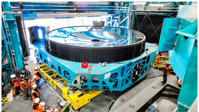
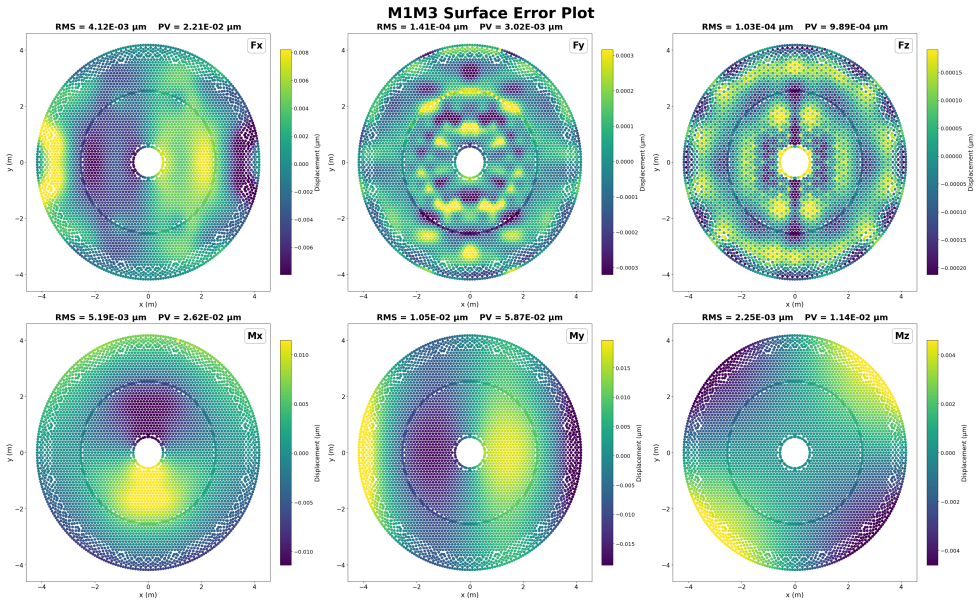
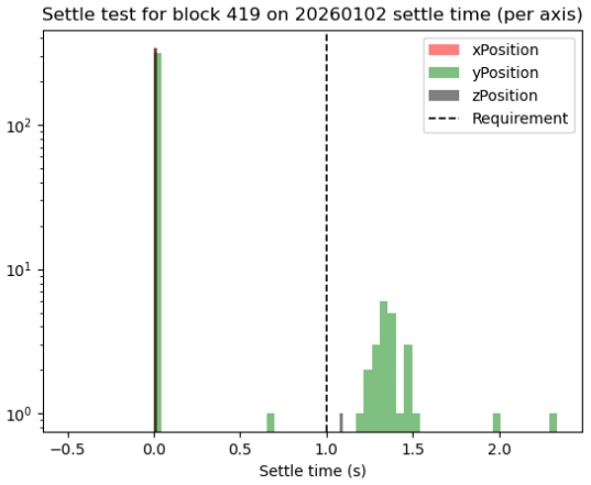
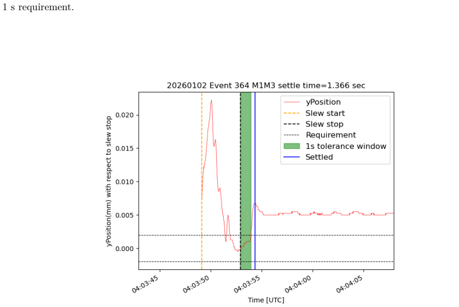
The Vera C. Rubin Observatory is preparing to commence the Legacy Survey of Space and Time with the fully integrated Simonyi Survey Telescope. To verify that the primary/tertiary (M1M3) mirror system is ready to meet the demanding survey requirements, dynamic tests of the 8.4 m, 53 ton M1M3 system were conducted to assess safety, stability, and image quality under realistic operating conditions. The M1M3 is supported by 156 pneumatic force actuators and positioned, relative to its mirror cell, by six hardpoint actuators that together must counteract gravitational and inertial loads during rapid telescope motion. The Rubin Observatory telescope mount is capable of moving at a rate that meets its nominal motion requirements, and can approach it maximum allowable values that are 50 percent higher. Even at just 20 % of its operational speed, it is an exceptionally fast motion for such a large structure. After slewing, the system must stabilize and dampen vibrations within 5 seconds to ensure image quality during observations. Achieving this rapid settling requires precise control of 156 force actuators, which must adjust dynamically with changes in telescope elevation to compensate for gravity effects. We present results for M1M3 from a comprehensive series of TMA dynamical tests spanning the operational envelope of slew velocities and accelerations. The analysis evaluates elevation axis balancing and lookup table updating as we install the M1M3 mirror; slew-and-settle behavior, force response and stability of the pneumatic actuator system across telescope attitudes including responses to the earthquake. The results demonstrate the readiness of the M1M3 subsystem for routine survey operations and provide validation data for ongoing performance modeling.
Figures
Figures from the paper (13 more)
Reference graph
Works this paper leans on
-
[1]
Lsst: from science drivers to reference design and anticipated data products,
Željko Ivezić et.al, “Lsst: from science drivers to reference design and anticipated data products,” The Astrophysical Journal 873(2), 111 (2019)
work page 2019
-
[2]
The LSST commissioning camera status and progress,
James Howard et.al, “The LSST commissioning camera status and progress,” in [ Ground-based and Airborne Telescopes VII], Marshall, H. K. and Spyromilio, J., eds., 10700, 107003D, International Society for Optics and Photonics, SPIE (2018)
work page 2018
-
[3]
Design and development of the 3.2 gigapixel camera for the Large Synoptic Survey Telescope,
S. M. Kahn et.al, “Design and development of the 3.2 gigapixel camera for the Large Synoptic Survey Telescope,” in [ Ground-based and Airborne Instrumentation for Astronomy III ], McLean, I. S., Ramsay, S. K., and Takami, H., eds., 7735, 77350J, International Society for Optics and Photonics, SPIE (2010)
work page 2010
-
[4]
Rubin M1M3 support system dynamic performance,
Quint, B. C., Daruich, F., Kubánek, P., Neill, D. R., Megias, G., Shestakov, A., Shugart, A., Jeremie, A., Levine, B., Stalder, B., Lage, C., Sanmartim, D., Boutigny, D., Urbach, E., Dennihy, E., Arancibia, F. M., Drass, H., Park, H., Sevilla-Noarbe, I., Sotuela, I., Sebag, J., Hernández, J., Carlin, J., Aubel, K., Fanning, K., Reil, K., Cipriano, L. T. S...
work page 2026
-
[5]
Final design of the LSST primary/tertiary mirror cell assembly,
Neill, D. R., Muller, G., Hileman, E., DeVries, J., Araujo, C., Gressler, W. J., Lotz, P. J., Mills, D., Sebag, J., Thomas, S., Warner, M., and Wiecha, O., “Final design of the LSST primary/tertiary mirror cell assembly,” in [ Ground-based and Airborne Telescopes VI ], Hall, H. J., Gilmozzi, R., and Marshall, H. K., eds., 9906, 99060Q, International Socie...
work page 2016
-
[6]
Lsst m1m3 figure actuator final design, fabrication, and test,
Muller, G. P., Hileman, E. A., Daruich, F., Warner, M., Wiecha, O. M., Araujo, C., Mills, N., Johnson, B. E., Stover, E., Booth, M. T., et al., “Lsst m1m3 figure actuator final design, fabrication, and test,” in [Ground-based and Airborne Telescopes VII ], 10700, 1224–1242, SPIE (2018)
work page 2018
-
[7]
LSST hardpoints final design, fabrication, and test,
Booth, M. T., Clements, A., and Johnson, B., “LSST hardpoints final design, fabrication, and test,” in [Ground-based and Airborne Telescopes VII ], Marshall, H. K. and Spyromilio, J., eds., Society of Photo- Optical Instrumentation Engineers (SPIE) Conference Series 10700, 107003S (July 2018)
work page 2018
-
[8]
Ashby, D. S., Kern, J., Hill, J. M., Davison, W. B., Cuerden, B., Brynnel, J. G., Biddick, C., and Duffek, K., “The Large Binocular Telescope primary mirror support control system description and current performance results,” in [ Advanced Optical and Mechanical Technologies in Telescopes and Instrumentation ], Atad- Ettedgui, E. and Lemke, D., eds., Soci...
work page 2008
Show all 16 references
-
[9]
Simonyi Survey Telescope M1M3 control system,
Petr Kubánek et.al, “Simonyi Survey Telescope M1M3 control system,” in [ Software and Cyberinfrastructure for Astronomy VII ], Ibsen, J. and Chiozzi, G., eds., 12189, 121890H, International Society for Optics and Photonics, SPIE (2022)
2022
-
[10]
LSST telescope modeling overview,
J. Sebag et.al, “LSST telescope modeling overview,” in [ Modeling, Systems Engineering, and Project Man- agement for Astronomy VII ], Angeli, G. Z. and Dierickx, P., eds., 9911, 99112E, International Society for Optics and Photonics, SPIE (2016)
2016
-
[11]
Baseline design of the LSST telescope mount assembly,
Douglas R. Neill et.al, “Baseline design of the LSST telescope mount assembly,” in [ Ground-based and Airborne Telescopes V ], Stepp, L. M., Gilmozzi, R., and Hall, H. J., eds., 9145, 914518, International Society for Optics and Photonics, SPIE (2014)
2014
-
[12]
Active optics control development at the lbt,
Ashby, D. S., Biddick, C., and Hill, J. M., “Active optics control development at the lbt,” in [ Ground-based and Airborne Telescopes V ], 9145, 1051–1066, SPIE (2014)
2014
-
[13]
Determining stress-based bending mode limits for the vera c. rubin observatory m1m3 active mirror system,
Malhar et.al, “Determining stress-based bending mode limits for the vera c. rubin observatory m1m3 active mirror system,” in [ Ground-based and Airborne Telescopes XI ], 14147, in press, International Society for Optics and Photonics, SPIE (2026)
2026
-
[14]
Telescope testing with active m1m3/m2 cells: mass balance and dynam- ics performance during the commissioning of vera c. rubin observatory,
Freddy Muñoz Arancibia et.al, “Telescope testing with active m1m3/m2 cells: mass balance and dynam- ics performance during the commissioning of vera c. rubin observatory,” in [ Ground-based and Airborne Telescopes XI], 14147, in press, International Society for Optics and Phot...
2026
-
[15]
Rubin Observatory Simonyi Survey Telescope integrated mount performance,
Stalder, B., Munoz, F., Aguilar, C., Araya, C., Aubel, K., Barr, J., Borstad, A., Claver, C., Clements, A. W., Constanzo, J., Corvetto, G., Coughlin, E., Daruich, F., Dennihy, E., Drass, H., Esteves, J., Fábrega, J., Fanning, K., Ferguson, P., Fernandez, M. G., Fernandez, M., ...
2024
-
[16]
Lsst m1m3 active mirror support system optimized to accommodate rapid telescope motions,
Felipe Daruich et.al, “Lsst m1m3 active mirror support system optimized to accommodate rapid telescope motions,” in [ Ground-based and Airborne Telescopes VII ], 10700, 1091–1106, SPIE (2018)
2018
Reviewed July 2, 2026 · model on record in the stance chip above.
Discussion (0). Sign in to comment.