REVIEW 4 major objections 6 minor 57 references
Inverse heterodyne effect in bimodal Kelvin probe force microscopy
T0 review · 4 major / 6 minor · reviewed 2026-08-02 · deepseek-v4-flash
Pith's one-line read Open-loop amplitude-modulated heterodyne KPFM sustains an inverse heterodyne effect: the second eigenmode feeds back onto the first, predominantly through dissipation.
desk verdict The inverse heterodyne back-action is real and the line-shape predictions are sharp, but the quantitative core leans on an unavailable companion paper. read the letter →
The pith
A machine-rendered reading of the paper's core claim, the machinery that carries it, and where it could break.
The reading
What carries the argument
The central object is the interaction-shifted second-eigenmode transfer function G2(omega2) and the dimensionless frequency ratio u2 = omega2 / omega-tilde_2,0, which together shape the inverse heterodyne terms: |G2|^2 governs the dissipation back-action and |G2|^2*(1-u2^2) gives the sign-changing conservative back-action. The argument is carried by inserting the non-truncated capacitance-gradient expansion (effective coefficients K0, K1, K2) into the bimodal electrostatic force, then projecting the total force onto the virial and power-balance equations of each eigenmode.
What would settle it
A decisive check would be to measure the first-mode drive force while sweeping the demodulation frequency across the second-mode resonance and compare the full width at half maximum of the dissipation peak to 1/sqrt(3) times the width of the directly measured second-mode amplitude resonance; if the width ratio differs significantly from 1/sqrt(3), the inverse heterodyne back-action is not the dominant mechanism.
Extended reading notes
Core claim
The central claim is that in open-loop AM-He-KPFM, heterodyne frequency conversion does more than excite the second eigenmode; it also produces a back-action force at the first eigenmode frequency. That back-action enters the first-mode power balance as a term proportional to alpha1*alpha2*|G2(omega2)|^2, making the required drive force increase with a resonance peak at the interaction-shifted second-mode frequency, and enters the first-mode virial as a term proportional to alpha1*alpha2*|G2(omega2)|^2*(1-u2^2), which changes sign across that resonance. Here alpha1 and alpha2 are electrostatic force amplitudes that vanish when the applied DC bias equals the contact potential difference or wh
Load-bearing premise
The load-bearing premise is that the effective capacitance-gradient coefficients (K0, K1, K2) from the companion manuscript are correct, and that the phases satisfy the quasi-quadrature condition |epsilon|<<1; if either fails, the quantitative predictions lose accuracy, although the sign-changing and squared-transfer-function line shapes may persist.
Editorial extensions
If this is right
- When sweeping the demodulation frequency around the second-mode resonance in open-loop AM-He-KPFM, the first-mode drive force will show a narrow resonance peak with a full width at half maximum about 1/sqrt(3) times that of the second-mode amplitude resonance, directly revealing the inverse back-action.
- The first-mode frequency shift will show a smaller, dispersive-like signature that changes sign at the interaction-shifted second-mode resonance, acting as an apparent stiffening or softening of the first mode.
- The inverse effect makes both the drive force and frequency shift depend quadratically on (VDC minus V_cpd) and on U_mod, so voltage- and modulation-dependent measurements must account for it to recover the true capacitance-gradient signal.
- In ideal closed-loop KPFM, the inverse effect vanishes because alpha1 and alpha2 go to zero, so the bimodal force expressions reduce to the usual monomodal ones; but any residual (VDC minus V_cpd) will reintroduce back-action.
- The same back-action mechanism transfers to dual-heterodyne KPFM and heterodyne photo-induced force microscopy, where a similar dissipation resonance should appear.
Reading between the lines
- The line-shape predictions (|G2|^2 and (1-u2^2)) are independent of the specific capacitance-gradient coefficients; if the companion's coefficients were found to be inaccurate, the strength and distance dependence would change but the resonance and sign-change signatures would survive, providing a way to separate the two parts of the theory.
- The dissipation-channel readout may offer a sensitive way to locate the interaction-shifted second-mode resonance even when the second-mode amplitude signal is weak, since the inverse effect amplifies via the square of the transfer function.
- The paper's experiments show an additional VDC-dependent dissipative contribution not captured by the model; identifying its microscopic origin (e.g., non-contact friction from surface charges) could refine quantitative dissipation-based KPFM.
- The effect could be tested in other multimode systems: any two coupled oscillators with a nonlinear force and frequency conversion should show an analogous back-action peak in the drive of the lower mode, scaled by the square of the higher-mode transfer function.
Signed reviews
Editorial analysis
A structured set of objections, weighed in public.
Referee Report
Summary. The paper develops an analytical bimodal virial/power-balance description of open-loop amplitude-modulated heterodyne KPFM and claims that the electrostatically driven second eigenmode feeds back onto the first eigenmode, producing an 'inverse heterodyne' contribution to the first-mode frequency shift and dissipation. The central results are Eq. (23): the first-mode drive acquires a term proportional to alpha1*alpha2*|G2|^2, and the frequency shift acquires a term proportional to alpha1*alpha2*|G2|^2*(1-u2^2). The theory predicts that the inverse effect appears mainly as a dissipation signal with a resonance peak in Vd(f2) that is about 1/sqrt(3) narrower than the second-mode transfer-function modulus, together with a sign-changing contribution to Delta-f1. The UHV experiments in Sec. V are presented as direct evidence, showing the predicted narrowing, the dispersive Delta-f1 lobe, and approximately quadratic VDC/Umod dependences. The manuscript also connects the effect to DHe-KPFM and He-PiFM and to broader multimode back-action phenomena.
Significance. If correct, the paper identifies a previously overlooked inter-mode back-action mechanism in a widely used KPFM variant and provides falsifiable predictions: the squared-transfer-function dissipation peak, the 1/sqrt(3) linewidth ratio, and the sign-changing (1-u2^2) conservative term. These are derived, not fit, and the f2-sweep data in Fig. 5 appear to match them. The direct-heterodyne scalings in Figs. 2-4 also provide useful independent cross-checks. However, the quantitative strength of the inverse effect is controlled by capacitance-gradient coefficients K1, K2 taken from an unavailable companion manuscript, and the central equations contain a dimensional inconsistency that must be resolved before the quantitative claims can be accepted.
major comments (4)
- [Eq. (23a,b)] The inverse-heterodyne terms in Eq. (23) have inconsistent dimensions. Since alpha_i has units N/m, ek2 has N/m, and |G2| has m/N, the term alpha1*alpha2/(2 ek2)*|G2|^2 in Eq. (23a) has units m/N inside a bracket that must have N/m; the same problem appears in Eq. (23b) with alpha1*alpha2/(ek2 Q2)*|G2|^2. Re-deriving from Eqs. (21)-(22) with z2,0 = z1,0*alpha1*|G2|, sin(epsilon)=cos(Phi_G2)=(1-u2^2)*ek2*|G2|, and cos(epsilon)=-sin(Phi_G2)=(u2/Q2)*ek2*|G2| gives bracket terms alpha1*alpha2*ek2/2*(1-u2^2)*|G2|^2 and alpha1*alpha2*u2*ek2/Q2*|G2|^2. This is not a minor typo: the magnitude difference is huge (order ek2^2) and directly affects the theoretical curves in Sec. V B 1. Please correct the equations or show an alternative derivation.
- [Sec. II C and Sec. V B 1] The effective capacitance-gradient coefficients K0, K1, K2, and the FOTR expressions of Eq. (9), are taken from the companion manuscript [25], which is not available to the reader or reviewer. The key f2-sweep experiment (Fig. 5) was performed at Delta-f1 = -100 Hz, z1,0 = 12 nm, Umod = 1 V, VDC = +1 V, i.e., at close approach where the truncation may not be controlled. The quantitative agreement claimed in Sec. V B 1 depends on the companion's derivation and convergence analysis. Please include the necessary definitions, convergence tests, or validation in the main text or SI, or otherwise make the companion accessible. The qualitative line-shape predictions are independent of this issue, but the force magnitudes and distance dependence are not.
- [Eq. (19) and Sec. V B 1] Eq. (23) is stated to be derived under the quasi-quadrature condition |epsilon| << 1, Eq. (19). However, the experimental comparison in Fig. 5 sweeps f2 over a range where epsilon is not small. If Eq. (23) is intended to hold over the full sweep, the derivation must be shown to follow from the exact transfer-function phase (Eq. 27), not from the small-epsilon approximation; otherwise the apparent match in Fig. 5 may be deceptive. Please either re-derive Eq. (23) without the small-epsilon assumption, or restrict the quantitative comparison to a narrow band around resonance and justify the validity outside it.
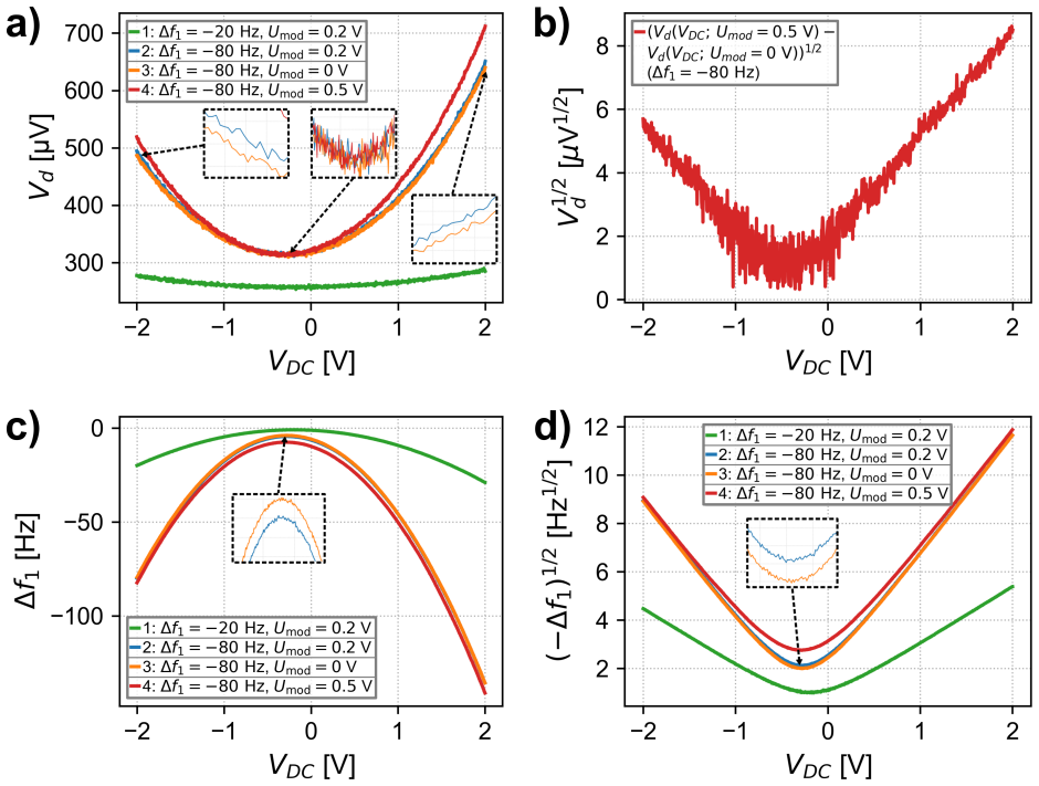
- [Sec. V B 2 and Eq. (23b)] The Vd(VDC) curves in Fig. 6(a) are explicitly stated to be dominated by a VDC-dependent dissipative contribution that is not described by the model and is formally absorbed into k_int,1^(d). The inverse-heterodyne contribution is isolated only by subtracting the Umod = 0 curve (Fig. 6b). This subtraction assumes the background dissipation is independent of Umod, but the same k_int,1^(d) term is later invoked to explain the Umod=0 offset in Fig. 7(a). The assumption is thus load-bearing for the claimed quadratic-in-Umod scaling. Please provide a test of this assumption, e.g., a Vd(VDC) measurement at Umod=0 as a baseline at the same zc, or a model for the VDC dependence of k_int,1^(d).
minor comments (6)
- [Sec. IV C] The signs of the (1-u2^2) term and the 'changes sign at resonance' discussion should specify that the sign change occurs at the interaction-shifted resonance ef2,0(zc), not at the free resonance f2,0.
- [Fig. 5 caption] The theoretical curves are 'scaled by prefactors' but the scaling is not defined; please specify the exact normalization so the reader can compare magnitudes.
- [Sec. V B 2/3 and Eqs. (28)-(29)] When plotting square roots of differences of Vd curves, the quantity under the square root may be negative on one side of VCPD; please specify whether absolute values or only positive branches are used, and add error bars or uncertainty estimates.
- [Table I and Sec. V B 1] Table I lists VDC = +200 mV and Umod = 200 mV, but the f2-sweep experiment uses VDC = +1 V and Umod = 1 V. Please clarify which parameters are nominal and which are changed in specific measurements.
- [Sec. V experimental setup] The statement that z2,0 is estimated from the Fourier peak ratio z1,0/68 is acknowledged as calibration-uncertain. This is acceptable because the main predictions for Fd and Delta-f1 do not depend on z2,0, but the uncertainty should be propagated if z2,0 values are quoted quantitatively.
- [Reference [25]] The companion manuscript is listed as 'submitted to APS Open Sci'; if available as a preprint, a link should be provided, and key results should be summarized in the SI for the present paper to be self-contained.
Circularity Check
No circularity: the inverse-heterodyne line-shape predictions are derived, not fitted; reliance on companion K_i coefficients is an external-support gap, not a circular reduction.
full rationale
Walking the derivation chain: the inverse-heterodyne force components (Eqs. 10a–10b) follow from inserting the CG expansion (Eq. 9) into the electrostatic force components (Eq. 8), and the observables (Eqs. 21–23) follow from the virial and power-balance equations (Eq. 4) under the stated quasi-quadrature condition (Eq. 19). No step redefines an output as an input or fits a parameter to the quantity being predicted. The central discriminating predictions — Fd scaling as |G2|^2 with the 1/√3 linewidth narrowing, and Δω1 scaling as |G2|^2(1 − u2^2) with a sign change at resonance — are derived functional forms of the second-mode transfer function and are not used to set any constant; the experimental f2 sweeps confirm these shapes. The effective CG coefficients K0,K1,K2 enter only as prefactors; their full non-truncated derivation is delegated to the concurrently submitted companion [25]. This is a genuine verification gap and a potential correctness risk if the companion treatment is inaccurate, but it is not circularity: the companion is not fitted to the target observables, and the qualitative line-shape signatures do not depend on its numerical values. The additional VDC-dependent dissipation absorbed into k(d)int,1 is explicitly acknowledged as a residual term, not as a source of the central prediction. Therefore the derivation chain is self-contained for the effect's existence and main signatures, with no circular step identified.
Assumptions & free parameters
free parameters (3)
- z2,0 calibration factor =
z1,0/68 = (0.18 +/- 0.02) nm
- quasi-quadrature detuning epsilon =
not quantified; assumed |epsilon| << 1
- modulation phase Phi_mod =
not reported
assumptions (6)
- domain assumption Bimodal SHO decomposition: the cantilever deflection is a superposition of two independent damped linear oscillators with harmonic steady-state motion.
- domain assumption Electrostatic force law Fel = (1/2) C'(z) [VDC - Vcpd + Vmod(t)]^2, with Vmod(t) = Umod cos(omega_mod t + Phi_mod).
- domain assumption The effective capacitance-gradient coefficients K0, K1, K2 and their FOTR expressions from the companion manuscript [25] are valid under the experimental bimodal trajectories.
- domain assumption Quasi-quadrature phase condition Phi_mod + Phi_1 - Phi_2 = +pi/2 - epsilon, with |epsilon| << 1.
- domain assumption Off-resonant omega_mod sidebands and all 2*omega_mod sidebands can be neglected because they do not contribute at omega_1 or omega_2.
- ad hoc to paper The unexplained, dominant VDC-dependent dissipation can be absorbed into the interaction term k_int,1^(d) without contaminating the inverse-heterodyne comparison.
Cite this review
Pith. "Pith review of Inverse heterodyne effect in bimodal Kelvin probe force microscopy." pith.science (2026). https://pith.science/paper/B6N7MA2F
@misc{pith2026260706135,
  author       = {Pith},
  title        = {Pith review of: Inverse heterodyne effect in bimodal Kelvin probe force microscopy},
  year         = {2026},
  howpublished = {\url{https://pith.science/paper/B6N7MA2F}},
  note         = {Machine review of arXiv:2607.06135}
}
read the original abstract
Heterodyne Kelvin probe force microscopy (He-KPFM) enables high-sensitivity electrostatic measurements by converting a bias-modulated interaction into a resonant response at a higher cantilever eigenmode. While the "direct" heterodyne actuation of the second eigenmode is well established, the dynamical back-action of this heterodyne-driven motion on the fundamental eigenmode has remained largely unexplored, particularly in open-loop operation where the second mode is excited to a finite amplitude. Here, we demonstrate an inverse heterodyne effect: a force component generated by heterodyne frequency conversion acts back on the first eigenmode and produces measurable inter-mode energy exchange. The analysis combines a bimodal virial and power-balance framework with a non-truncated description of the tip-surface capacitance-gradient dynamics developed and validated in a companion manuscript submitted concurrently to the same journal. On this basis, we derive closed-form expressions linking inverse heterodyne coupling to the experimentally accessible observables of non-contact AFM open-loop amplitude-modulated He-KPFM. The theory predicts that inverse heterodyne coupling appears predominantly in the dissipation channel, with a sharply resonant dependence on the demodulation frequency near the second-eigenmode resonance, while its conservative contribution to the frequency shift remains comparatively weaker under typical conditions. Ultrahigh-vacuum experiments validate these predictions and isolate the inverse heterodyne signature through frequency- and voltage-dependent measurements. Beyond KPFM, this work connects heterodyne force microscopy to a broader class of driven multimode systems in which nonlinear coupling and frequency conversion produce inter-mode energy transfer, back-action, and dissipation-based observables.
Figures


Figures from the paper (11 more)




Reference graph
Works this paper leans on
-
[25]
Valloire, S
H. Valloire, S. Clair, C. Loppacher, L. Nony, and B. Gr´ evin, On the capacitance gradient description in heterodyne kelvin probe force microscopy (2026), submitted to APS Open Sci
2026
-
[1]
Nonnenmacher, M
M. Nonnenmacher, M. O’Boyle, and H. Wickramasinghe, Appl. Phys. Lett.58, 2921 (1991)
1991
-
[2]
Melitz, J
W. Melitz, J. Shen, A. Kummel, and S. Lee, Surf. Sci. Rep.66, 1 (2011)
2011
-
[3]
Sadewasser and T
S. Sadewasser and T. Glatzel, eds.,Kelvin Probe Force Microscopy: Measuring and Compen- sating Electrostatic Forces, Vol. 48 (Springer, 2012)
2012
-
[4]
Sadewasser and T
S. Sadewasser and T. Glatzel, eds.,Kelvin Probe Force Microscopy: From Single Charge Detection to Device Characterization, Vol. 65 (Springer, 2018)
2018
-
[5]
Lord Kelvin (William Thomson), Philosophical Magazine Series 546, 82 (1898)
-
[6]
Zisman, Rev
W. Zisman, Rev. Sci. Instrum.3, 367 (1932)
1932
-
[7]
Magonov and J
S. Magonov and J. Alexander, Beilstein J. Nanotechnol.2, 15 (2011)
2011
Show all 57 references
-
[8]
Borgani, D
R. Borgani, D. Forchheimer, J. Bergqvist, P.-A. Thor´ en, O. Ingan¨ as, and D. Haviland, Appl. Phys. Lett.105, 143113 (2014)
2014
-
[9]
Collins, M
L. Collins, M. Okatan, Q. Li, I. Kravenchenko, N. Lavrik, S. Kalinin, B. Rodriguez, and S. Jesse, Nanotechnology26, 175707 (2015)
2015
-
[10]
Rohrbeck, L
P. Rohrbeck, L. Cavar, F. Weber, P. Reichel, M. Niebling, and S. Weber, Beilstein J. Nan- otechnol.16, 637 (2025)
2025
-
[11]
Kikukawa, S
A. Kikukawa, S. Hosaka, and R. Imura, Rev. Sci. Instrum.67, 1463 (1996)
1996
-
[12]
Kitamura and M
S. Kitamura and M. Iwatsuki, Appl. Phys. Lett.72, 3154 (1998)
1998
-
[13]
Zerweck, C
U. Zerweck, C. Loppacher, T. Otto, S. Grafstr¨ om, and L. Eng, Phys. Rev. B71, 125424 (2005)
2005
-
[14]
Kilpatrick, L
J. Kilpatrick, L. Collins, S. Weber, and B. Rodriguez, Rev. Sci. Instrum.89, 123708 (2018)
2018
-
[15]
Sugawara, L
Y. Sugawara, L. Kou, Z. Ma, T. Kamijo, Y. Naitoh, and Y. J. Li, Appl. Phys. Lett.100, 223104 (2012)
2012
-
[16]
Borgani and D
R. Borgani and D. Haviland, Rev. Sci. Instrum.90, 013705 (2019)
2019
-
[17]
Gr´ evin, F
B. Gr´ evin, F. Husainy, D. Aldakov, and C. Auma ˆ ıtre, Beilstein J. Nanotechnol.14, 1068 (2023)
2023
-
[18]
Lozano and R
J. Lozano and R. Garcia, Phys. Rev. B79, 014110 (2009)
2009
-
[19]
Herruzo and R
E. Herruzo and R. Garcia, Beilstein J. Nanotechnol.3, 198 (2012)
2012
-
[20]
Kiracofe, A
D. Kiracofe, A. Raman, and D. Yablon, Beilstein J. Nanotechnol.4, 385 (2013)
2013
-
[21]
S. An, S. Solares, S. Santos, and D. Ebeling, Nanotechnology25, 475701 (2014)
2014
-
[22]
Giessibl and H
F. Giessibl and H. Bielefeldt, Phys. Rev. B61, 9968 (2000). 39
2000
-
[23]
Miyahara, J
Y. Miyahara, J. Topple, Z. Schumacher, and P. Gr¨ utter, Phys. Rev. Applied4, 054011 (2015)
2015
-
[24]
Miyahara and P
Y. Miyahara and P. Gr¨ utter, Appl. Phys. Lett.110, 163103 (2017)
2017
-
[26]
Jahng, B
J. Jahng, B. Kim, E. Lee, and E. Potma, Phys. Rev. B94, 195407 (2016)
2016
-
[27]
Yamanishi, Y
J. Yamanishi, Y. Naitoh, Y. Li, and Y. Sugawara, Appl. Phys. Lett.110, 123102 (2017)
2017
-
[28]
Shcherbakov, E
M. Shcherbakov, E. Potma, Y. Sugawara, D. Nowak, M. Stepanova, P. Davies, J. Davies-Jones, and H. Wickramasinghe, Nat. Rev. Methods Primers5, 34 (2025)
2025
-
[29]
Rodr ´ ıguez and R
T. Rodr ´ ıguez and R. Garc ´ ıa, Appl. Phys. Lett.84, 449 (2004)
2004
-
[30]
Lozano and R
J. Lozano and R. Garcia, Phys. Rev. Lett.100, 076102 (2008)
2008
-
[31]
Melcher, S
J. Melcher, S. Hu, and A. Raman, Appl. Phys. Lett.91, 053101 (2007)
2007
-
[32]
Kawai, T
S. Kawai, T. Glatzel, S. Koch, B. Such, A. Baratoff, and E. Meyer, Phys. Rev. Lett.103, 220801 (2009)
2009
-
[33]
C.-Y. Lai, V. Barcons, S. Santos, and M. Chiesa, J. Appl. Phys.118, 044905 (2015)
2015
-
[34]
Bonnell, D
D. Bonnell, D. Basov, M. Bode, U. Diebold, S. Kalinin, V. Madhavan, L. Novotny, M. Salmeron, U. Schwarz, and P. Weiss, Rev. Mod. Phys.84, 1343 (2012)
2012
-
[35]
A. Axt, I. Hermes, V. Bergmann, N. Tausendpfund, and S. Weber, Beilstein J. Nanotechnol.9, 1809 (2018)
2018
-
[36]
Garrett, M
J. Garrett, M. Leite, and J. Munday, ACS Appl. Mater. Interfaces10, 28850 (2018)
2018
-
[37]
Garrett, D
J. Garrett, D. Somers, K. Sendgikoski, and J. Munday, Phys. Rev. A100, 022508 (2019)
2019
-
[38]
Danmarksgatan 22, 75323 Uppsala, Sweden
-
[39]
RHK Technology, Inc., 1409 Allen Drive – Ste F, Troy, MI, US 48083
-
[40]
NANOSENSORS, Rue des Saars 10, CH-2000 Neuchatel, Switzerland
2000
-
[41]
G. H. Simon, M. Heyde, and H.-P. Rust, Nanotechnology18, 255503 (2007)
2007
-
[42]
Heile, R
D. Heile, R. Olbrich, M. Reichling, and P. Rahe, Phys. Rev. B103, 075409 (2021)
2021
-
[43]
Aubriet, K
V. Aubriet, K. Courouble, O. Bardagot, R. Demadrille, L. Borowik, and B. Gr´ evin, Nanotech- nology33, 225401 (2022)
2022
-
[44]
Zurich Instruments AG, Technoparkstrasse 1, 8005 Zurich, Switzerland
-
[45]
Crowley, Proc
J. Crowley, Proc. Electrochem. Soc. Am. Annu. Meet. Electrost.Paper D1, 1 (2008)
2008
-
[46]
Denk and D
W. Denk and D. Pohl, Appl. Phys. Lett.59, 2171 (1991)
1991
-
[47]
Stowe, T
T. Stowe, T. Kenny, D. Thomson, and D. Rugar, Appl. Phys. Lett.75, 2785 (1999). 40
1999
-
[48]
Dorofeyev, H
I. Dorofeyev, H. Fuchs, G. Wenning, and B. Gotsmann, Phys. Rev. Lett.83, 2402 (1999)
1999
-
[49]
Loppacher, R
C. Loppacher, R. Bennewitz, O. Pfeiffer, M. Guggisberg, M. Bammerlin, S. Sch¨ ar, V. Barwich, A. Baratoff, and E. Meyer, Phys. Rev. B62, 13674 (2000)
2000
-
[50]
Pfeiffer, L
O. Pfeiffer, L. Nony, R. Bennewitz, A. Baratoff, and E. Meyer, Nanotechnology15, S101 (2004)
2004
-
[51]
Dwyer, L
R. Dwyer, L. Harrell, and J. Marohn, Phys. Rev. Applied11, 064020 (2019)
2019
-
[52]
Hasan, T
M. Hasan, T. Arai, and M. Tomitori, Jap. J. Appl. Phys.61, 065006 (2022)
2022
-
[53]
Lekkala, J
S. Lekkala, J. Marohn, and R. Loring, J. Chem. Phys.139, 184702 (2013)
2013
-
[54]
Loring, J
R. Loring, J. Phys. Chem. A126, 6309 (2022)
2022
-
[55]
C. Chen, D. Zanette, D. Czaplewski, S. Shaw, and D. L´ opez, Nat. Commun.8, 15523 (2017)
2017
-
[56]
Asadi, J
K. Asadi, J. Yu, and H. Cho, Philos. Trans. A Math. Phys. Eng. Sci.376, 20170141 (2018)
2018
-
[57]
Fu, Z.-C
H. Fu, Z.-C. Gong, T.-H. Mao, C.-Y. Shen, C.-P. Sun, S. Yi, Y. Li, and G.-Y. Cao, Phys. Rev. Applied11, 034010 (2019). 41 FIGURES FIG. 1:Geometry of the problem. Schematic representation of the cantilever oscillatory motion above the sample surface in the bimodal regime. The b...
2019
Reviewed August 2, 2026 · model on record in the stance chip above.
Discussion (0). Continue with ORCID to comment.