REVIEW 3 major objections 9 minor 96 references
Divertor topology and vacuum vessel design for stellarators
T0 review · 3 major / 9 minor · reviewed 2026-07-30 · grok-4.5
Pith's one-line read Stellarator coils and vessels can be optimized together so the edge magnetic field forms chosen divertor topologies, including precise snowflake divertors.
desk verdict Solid methods paper that actually delivers stellarator snowflakes and joint coil–vessel control in vacuum; the engineering fragility of M=I is the real open question, not the numerics. read the letter →
The pith
A machine-rendered reading of the paper's core claim, the machinery that carries it, and where it could break.
The reading
What carries the argument
Stabilized spectral fixed-point solve: the field-line ODE is collocated in Fourier form and, for parabolic (degenerate) points, is augmented with trace or full tangent-map targets plus auxiliary poloidal-field coil degrees of freedom so Newton’s method stays well-conditioned; signed-distance vessel families then supply differentiable clearance constraints that couple divertor placement to vessel and coil geometry.
What would settle it
Build or rigorously model one of the optimized coil sets at finite plasma pressure and check whether the intended fixed-point type (especially the snowflake with return-map equal to the identity) still exists at the designed location with the same leg structure.
Extended reading notes
Core claim
A well-conditioned spectral solver for periodic magnetic field lines of any type (elliptic, hyperbolic, or parabolic), paired with parametric vacuum vessels that have efficient signed-distance functions, lets modular coils and the vessel be optimized together so vacuum stellarators achieve prescribed divertor topologies—including precise rank-0 parabolic snowflake divertors—while retaining nested surfaces, quasi-axisymmetry, magnetic well, and coil/vessel engineering constraints.
Load-bearing premise
The type and location of edge fixed points computed in vacuum (or at tiny plasma pressure) remain a good enough stand-in for the real divertor once the plasma itself makes a magnetic field.
Editorial extensions
If this is right
- Snowflake and other advanced tokamak-style divertors become designable options in stellarators, not only island divertors.
- Vacuum vessel shape can be a free variable in coil optimization rather than a post-hoc packing problem.
- A library of small quasi-axisymmetric devices with controlled single-null, double-null, parabolic, and snowflake edges can be generated for experimental comparison.
- Connection-length and strike-line patterns follow the chosen fixed-point topology across toroidal angle, guiding where divertor plates should sit.
Reading between the lines
- If vacuum snowflakes survive at reactor-relevant pressure, stellarators could borrow decades of tokamak snowflake heat-exhaust experience without axisymmetry.
- The same fixed-point continuation that converts O-points to X-points could be used online to retune edge topology with PF-coil currents during an experiment.
- Piecewise-cylinder and canal vessels with closed-form distances may make automated port and baffle packing a standard constraint in future coil codes.
Editorial analysis
A structured set of objections, weighed in public.
Referee Report
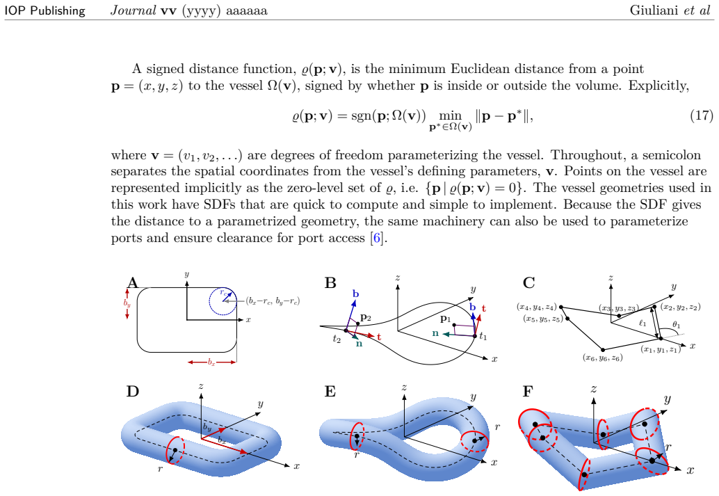
Summary. The paper presents two algorithms and their integration into a stellarator optimization framework. First, a spectral collocation/Newton method for computing periodic field lines (fixed points of the Poincaré return map) of arbitrary type — elliptic, hyperbolic, and parabolic — using augmented systems (trace or full-M targets with auxiliary PF-coil degrees of freedom) that keep the Jacobian well-conditioned through the degenerate parabolic limit; continuation examples convert O-points to X-points, heal and unfold a snowflake (rank-0 parabolic, M=I), and form an O-point chain. Second, parametric vacuum-vessel families (pill pipe, non-planar canal surface, piecewise mitered cylinders) with efficiently computable, differentiable signed distance functions. These are combined in a joint coil–vessel–fixed-point optimization with physics targets (quasi-axisymmetry, transform, aspect ratio, magnetic well) and engineering constraints (coil curvature, length, clearances), producing four STAR Lite-class two-field-period devices: double-null, single-null, rank-1 parabolic, and a six-legged snowflake. Edge characterization (FLARE connection lengths, strike maps) and vacuum/β=0.01% MHD proxies (Mercier, ballooning) are reported; the snowflake is Mercier-stable only in an intermediate region.
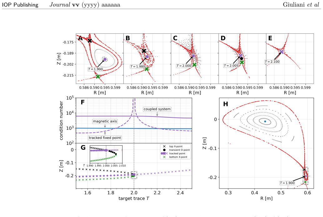
Significance. If the results hold, this is a substantial methods contribution: (i) the first demonstration of non-axisymmetric snowflake divertors in stellarators, extending a tokamak concept previously unrealized in 3D fields; (ii) a numerically well-conditioned solver for degenerate fixed points, demonstrated with bounded Jacobian condition numbers through bifurcations (Figs. 3F, 4D) — a real technical advance over naive Newton on the displacement map; (iii) closed-form or 1D-root-find signed distance functions for three parametric vessel families, enabling coil-on/off-vessel optimization with differentiable clearance constraints; (iv) a fully stated constrained optimization problem (App. A) with engineering bounds taken from the STAR Lite project, and post-hoc physics validation via connection lengths, strike maps, and Mercier/ballooning proxies at the experimental operating point. The honest reporting of the snowflake's limited Mercier-stable region and of the custom A_50% metric's caveats is commendable. The tools are broadly useful for stellarator edge design beyond STAR Lite.
major comments (3)
- [§4.2, §7, Fig. 4D, Fig. 8D] The headline result — 'precise' rank-0 snowflakes as STAR Lite prototype candidates — rests on enforcing M=I, a codimension-2 degenerate condition. Fig. 4 itself shows the snowflake unfolds into two X-points (or O + 3 X) when Tr(M) departs from 2 by ~0.05, yet nowhere is the sensitivity of M to the design variables quantified: no singular values of d(vec M)/dq, no tolerance on PF-coil currents, no Monte-Carlo over modular-coil manufacturing errors. App. C flags exactly this fragility for the magnetic well ('particularly sensitive to manufacturing errors') but the analogous analysis is missing for the edge fixed point. A snowflake holding Tr(M)=2 to 1e-4 vs 1e-2 are very different device propositions. Please add a vacuum-field error budget (e.g. condition number of the map from coil/PF perturbations to M, or an ensemble over plausible coil displacements). This is testable today within the
- [§6, Eqs. (25)-(26); §2.2, Fig. 2] The optimization constrains only Tr(M)=2 or M=I (Eqs. 25-26). But Fig. 2 shows that rank-0 (M=I) fixed points come in (at least) two-legged and six-legged varieties, and only the latter are snowflakes. Nothing in the constraint set or objective selects the six-legged topology or its unfolding direction; the six legs appear to be verified post hoc from Poincaré sections. Please state explicitly how the six-legged structure is obtained and whether it is robust: is leg count selected by the seed, by the PF-coil arrangement, or by higher-order terms in the return map? If a small perturbation of the converged design yields the two-legged rank-0 state instead, the 'snowflake' claim for Fig. 8D needs qualification.
- [§7.2, §8] All fixed-point locations/types are computed in vacuum; the stability proxies use a fixed-boundary β=0.01% equilibrium, and finite-β edge fixed points are deferred to virtual-casing/SPEC work (§8). This scoping is honestly stated, but the abstract and §8 then describe the devices as 'candidates for a next-generation STAR Lite prototype.' For the claim to stand, some estimate is needed of whether plasma-generated fields at the planned operating point move Tr(M) by less than the snowflake's fragility scale (see comment 1). Even an order-of-magnitude virtual-casing or diamagnetic-field estimate at the edge, compared against the field perturbation required to shift Tr(M) by 0.05, would bound the risk. Alternatively, temper the prototype language to 'magnetic-design candidates pending finite-β verification.'
minor comments (9)
- [§4.3] The text states the continuation varies T 'from 1.95 to 2.05, so that it transitions from hyperbolic to parabolic snowflake, then elliptic,' but two sentences later says the trace 'varies from 2.4 to 1.90.' The latter is consistent with X→O conversion; the former is not. Please correct.
- [§2.2] The rotation-matrix display for the elliptic case has a sign/glyph error (the off-diagonal should be -sin(α)); throughout the text the minus sign renders as '9' (e.g. 'Tr(M)<9 2', 'topological index ... is 9 2'). Please fix the typesetting.
- [§3.2] The sentence 'then, b representation is given in eq. (4)...' is garbled; presumably 'the n,b representation.'
- [§5, Eq. (23)] Eq. (23) is explicitly a level-set function, not a true SDF, yet it is used inside the distance constraints (24.1)-(24.3) whose bounds (d_coil-vessel etc.) are interpreted as physical distances. Please clarify which vessel family was used with Eq. (23) and how the clearance bounds were reinterpreted in that case.
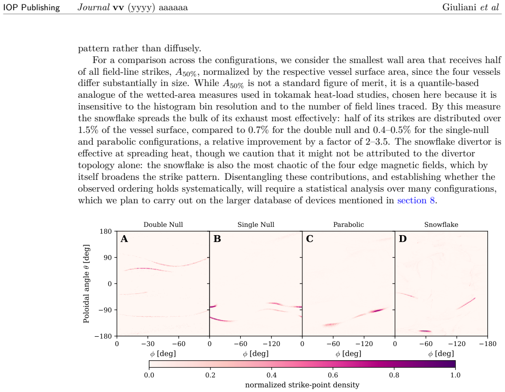
- [§7.1, Fig. 10] The A_50% measure is non-standard (as the authors note). Since the snowflake's 2-3.5x advantage may partly reflect edge chaos rather than topology, it would strengthen §7.1 to also report a standard quantity (wetted area at fixed diffusion, or flux expansion) for at least the snowflake and double-null cases.
- [§5] SDF spatial gradients are undefined when the nearest vessel point is non-unique (e.g. on the canal centerline). The text says this 'did not prevent' convergence; a sentence on how the optimizer avoids or handles these points (safeguarded line search, constraint margins) would help reproducibility.
- [§9] 'The scripts ... will be made publicly available in a repository on Zenodo.' Please deposit before publication and cite the DOI; the results (condition-number continuations, optimized devices) should be reproducible at review time for a methods paper.
- [Fig. 10 caption] Fig. 10 normalizes strike density per configuration; the caption should state explicitly that absolute magnitudes differ and point to the A_50% comparison for the common-scale statement.
- [§2.2] Eq. (6): the expression 'ι = nfp/2π α' is ambiguous (ι = nfp α/(2π)?). Please parenthesize.
Circularity Check
Constructive optimization paper: divertor type is enforced by explicit Tr(M)/M constraints and design targets, not predicted from fitted inputs; no load-bearing circular reduction.
full rationale
The paper’s central claims are algorithmic and constructive: a spectral Newton method for periodic orbits (including degenerate parabolic cases via augmented trace/M constraints), signed-distance vessel families, and joint coil–vessel optimization that realizes prescribed divertor topologies (X-point, single/double-null, rank-1 parabolic, rank-0 snowflake) under quasisymmetry, well, and engineering bounds. Fixed-point type is not derived from data or redefined as success; it is imposed by explicit algebraic targets (Tr(M)=T, M=I, or |Tr(M)−2|≤0.1) while free PF/modular degrees of freedom are solved for. Design targets (ι*, A*, B*, well bound, coil limits) are specifications, not fitted ‘predictions’ of nature. Self-citations ([30,31] Boozer surfaces, SIMSOPT, STAR Lite design A) supply infrastructure and initialization, not uniqueness theorems that force the snowflake claim. No equation reduces the existence of a snowflake or the vessel clearance result to its own input by construction. Minor self-use of prior tools does not raise circularity beyond a 1.
Assumptions & free parameters
free parameters (6)
- Target rotational transforms ι*_s, ι*_a and aspect ratio A* =
A*=6.66; ι targets as in STAR Lite-class runs
- On-axis mean field B* and magnetic-well bound W* =
B*=0.0875 T; W* example −100
- Coil current/geometry engineering bounds (I*, Lmax, κmax, d_cc, …) =
e.g. modular ≤60 kA·turns, PF ≤5 kA·turns, Lmax=3 m, d_cc=0.15 m
- Pairwise distance bounds d_coil-vessel, D_coil-vessel, d_divertor-vessel
- Auxiliary PF coil count, radii, vertical positions, currents η
- Near-parabolic seed tolerances |Tr(M)−2|≤0.1 or ||M−I||_∞≤0.1 =
0.1
assumptions (5)
- standard math Magnetic field lines form a Hamiltonian system, so det(M)=1 for the Poincaré return-map Jacobian (Abel–Liouville).
- domain assumption Vacuum fields from filamentary modular/PF coils adequately represent the edge for topology design at STAR Lite parameters.
- domain assumption Isolated parabolic fixed points with Tr(M)=+2 (rank-1 or rank-0/M=I) are the correct mathematical targets for stellarator snowflake/parabolic divertors.
- ad hoc to paper Signed-distance (or level-set) constraints on the chosen vessel families suffice to enforce non-intersection and clearance without needing fully free-form vessel CAD.
- ad hoc to paper Penalty method driving physics/engineering constraints to ~0.1% (or 0.1 absolute) yields designs that are acceptably feasible for prototype candidacy.
invented entities (2)
-
Augmented spectral Newton systems for parabolic fixed points (trace or full-M targets plus η DOFs)
independent evidence
-
Parametric SDF vessel families (pill pipe, non-planar canal, piecewise-cylinder/mitered)
independent evidence
Cite this review
Pith. "Pith review of Divertor topology and vacuum vessel design for stellarators." pith.science (2026). https://pith.science/paper/BR5JKZJ6
@misc{pith2026260727127,
  author       = {Pith},
  title        = {Pith review of: Divertor topology and vacuum vessel design for stellarators},
  year         = {2026},
  howpublished = {\url{https://pith.science/paper/BR5JKZJ6}},
  note         = {Machine review of arXiv:2607.27127}
}
read the original abstract
We present stellarator optimization algorithms for designing the edge magnetic structure in vacuum fields, together with the vacuum vessel. First, we introduce a numerical method that robustly computes periodic-orbit fixed points of any type (elliptic, hyperbolic, or parabolic), which could form the basis of a divertor. To couple divertor and vacuum vessel design, we introduce parametric families of vacuum vessels for which point-to-vessel distances, and their derivatives, can be computed efficiently. The resulting algorithms use signed distance functions to enforce coil-vessel clearance while allowing coils to be placed on or off the vessel. Using these methods, we jointly optimize modular coils and the vacuum vessel to realize a wide range of magnetic topologies for diverting exhaust, including standard X-point divertors, and single- and double-null configurations. For the first time, we show that precise snowflake divertors can be achieved in stellarators. Using this framework, we generate a number of quasi-axisymmetric stellarator designs with compatible vacuum vessels and diverse divertor architectures, which we consider to be candidates for a next-generation STAR Lite prototype.
Figures


Figures from the paper (9 more)






Reference graph
Works this paper leans on
-
[1]
Akers, J
R. Akers, J. Ahn, G. Antar, L. Appel, D. Applegate, C. Brickley, C. Bunting, P. Carolan, C. Challis, N. Conway, et al. Transport and confinement in the Mega Ampere Spherical Tokamak (MAST) plasma.Plasma physics and controlled fusion, 45(12A):A175–A204, 2003
2003
-
[2]
Akers, J
R. Akers, J. Ahn, L. Appel, E. Arends, K. Axon, R. Buttery, C. Byrom, P. Carolan, G. Counsell, G. Cunningham, et al. H-mode access and performance in the Mega-Amp Spherical Tokamak.Physics of Plasmas, 9(9):3919–3929, 2002
2002
-
[3]
Andreeva, J
T. Andreeva, J. Geiger, A. Dinklage, G. Wurden, H. Thomsen, K. Rahbarnia, J. Schmitt, M. Hirsch, G. Fuchert, C. N¨ uhrenberg, et al. Magnetic configuration scans during divertor operation of Wendelstein 7-X.Nuclear Fusion, 62(2):026032, 2022
2022
-
[4]
Aymar, P
R. Aymar, P. Barabaschi, and Y. Shimomura. The ITER design.Plasma physics and controlled fusion, 44(5):519–565, 2002
2002
-
[5]
Bader, A
A. Bader, A. Ayilaran, J. Canik, A. De, W. Guttenfelder, C. Hegna, M. Knilans, A. Malkus, T. Pedersen, P. Sinha, et al. Power and particle exhaust for the Infinity Two fusion pilot plant. Journal of Plasma Physics, 91(2):E67, 2025. 22 IOP PublishingJournalvv(yyyy) aaaaaa Giulianiet al
2025
-
[6]
Baillod, E
A. Baillod, E. J. Paul, T. Elder, and J. M. Halpern. Enhancing stellarator accessibility through port size optimization.Nuclear Fusion, 65(8):086040, 2025
2025
-
[7]
D. Bold and B. Shanahan. Numerical methods for stellarator simulations in bout++.arXiv preprint arXiv:2603.28221, 2026
arXiv 2026
-
[8]
A. H. Boozer. Stellarator design.Journal of Plasma Physics, 81(6):515810606, 2015
2015
Show all 96 references
-
[9]
Davies, D
R. Davies, D. Boeyaert, A. Wolfmeister, B. Geiger, G. Harrer, and J. Geiger. Computational studies of giant edge islands and unpaired X-points in HSX and W7-X by manipulating coil currents, 2026
2026
-
[10]
Davies, M
R. Davies, M. Drevlak, Y. Feng, J. Geiger, A. Goodman, C. Smiet, G. Plunk, P. Xanthopoulos, and S. Henneberg. Stellarator divertor optimisation for a Stable Quasi-Isodynamic Design (SQuID): magnetic topology, divertor plates and baffle design. In 51st EPS Conference on Plasma ...
2025
-
[11]
Davies, Y
R. Davies, Y. Feng, D. Boeyaert, J. C. Schmitt, M. J. Gerard, K. A. Garcia, O. Schmitz, B. Geiger, and S. A. Henneberg. A semi-automated algorithm for designing stellarator divertor and limiter plates and application to HSX.Nuclear Fusion, 64(12):126044, 2024
2024
-
[12]
Davies, C
R. Davies, C. B. Smiet, C. Batzdorf, J. Geiger, J. Loizu, and S. A. Henneberg. Characterisation of X-and O-points in Wendelstein 7-X with respect to coil currents.Journal of Plasma Physics, 92(2), 2026
2026
-
[13]
Davies, C
R. Davies, C. B. Smiet, A. Punjabi, A. H. Boozer, and S. A. Henneberg. The topology of non-resonant stellarator divertors.Nuclear Fusion, 65(7):076018, jun 2025
2025
-
[14]
Di Pietro, P
E. Di Pietro, P. Barabaschi, Y. Kamada, S. Ishida, et al. Overview of engineering design, manufacturing and assembly of JT-60SA machine.Fusion Engineering and Design, 89(9-10):2128–2135, 2014
2014
-
[15]
Drevlak, D
M. Drevlak, D. Monticello, and A. Reiman. PIES free boundary stellarator equilibria with improved initial conditions.Nuclear fusion, 45(7):731–740, 2005
2005
-
[16]
D. Eberly. Distance from a point to an ellipse, an ellipsoid, or a hyperellipsoid. https://geometrictools.com/Documentation/DistancePointEllipseEllipsoid.pdf,
-
[17]
T. Evans. Resonant magnetic perturbations of edge-plasmas in toroidal confinement devices. Plasma Physics and Controlled Fusion, 57(12):123001, 2015
2015
-
[18]
Y. Feng, H. Frerichs, M. Kobayashi, A. Bader, F. Effenberg, D. Harting, H. Hoelbe, J. Huang, G. Kawamura, J. Lore, et al. Recent improvements in the EMC3-EIRENE code.Contributions to Plasma Physics, 54(4-6):426–431, 2014
2014
-
[19]
Y. Feng, M. Kobayashi, T. Lunt, and D. Reiter. Comparison between stellarator and tokamak divertor transport.Plasma physics and controlled fusion, 53(2):024009, 2011
2011
-
[20]
Feng and W7-X-team
Y. Feng and W7-X-team. Review of magnetic islands from the divertor perspective and a simplified heat transport model for the island divertor.Plasma Physics and Controlled Fusion, 64(12):125012, 2022
2022
-
[21]
E. Flom, W. Kalb, S. Seethalla, C. Swanson, R. Wu, M. Avida, A. Doudna Cate, D. Dudt, T. Kruger, S. Kumar, N. Maitra, and D. Gates. Design and conceptual modeling of a tokamak-like X-point divertor for the Helios quasi-axisymmetric stellarator.Fusion Engineering and Design, 23...
2026
-
[22]
D. A. Frank-Kamenetskii.Interchange or Flute Instabilities, pages 98–100. Macmillan Education UK, London, 1972
1972
-
[23]
Frerichs
H. Frerichs. Flare: field line analysis and reconstruction for 3d boundary plasma modeling. Nuclear Fusion, 64(10):106034, sep 2024
2024
-
[24]
Frerichs, D
H. Frerichs, D. Boeyaert, Y. Feng, and D. Reiter. FIREFLY: heat load and particle exhaust approximations for rapid evaluation of divertor designs.arXiv preprint arXiv:2604.11497, 2026. 23 IOP PublishingJournalvv(yyyy) aaaaaa Giulianiet al
2026 arXiv
-
[25]
Gallo, N
A. Gallo, N. Fedorczak, S. Elmore, R. Maurizio, H. Reimerdes, C. Theiler, C. Tsui, J. A. Boedo, M. Faitsch, H. Bufferand, et al. Impact of the plasma geometry on divertor power exhaust: experimental evidence from tcv and simulations with soledge2d and tokam3x. Plasma Physics a...
2018
-
[26]
Gates, S
D. Gates, S. Aslam, B. Berzin, P. Bonofiglo, A. Cote, D. Dudt, E. Flom, D. Fort, A. Koen, T. Kruger, et al. Stellarator fusion systems enabled by arrays of planar coils.Nuclear Fusion, 65(2):026052, 2025
2025
-
[27]
Gates, A
D. Gates, A. Boozer, T. Brown, J. Breslau, D. Curreli, M. Landreman, S. Lazerson, J. Lore, H. Mynick, G. Neilson, et al. Recent advances in stellarator optimization.Nuclear Fusion, 57(12):126064, 2017
2017
-
[28]
R. Gaur, D. Panici, T. Elder, M. Landreman, K. Unalmis, Y. Elmacioglu, D. Dudt, R. Conlin, and E. Kolemen. Omnigenous umbilic stellarators.Journal of Plasma Physics, 91(6), 2026
2026
-
[29]
Geraldini, M
A. Geraldini, M. Landreman, and E. Paul. An adjoint method for determining the sensitivity of island size to magnetic field variations.Journal of Plasma Physics, 87(3):905870302, 2021
2021
-
[30]
Giuliani, F
A. Giuliani, F. Wechsung, A. Cerfon, G. Stadler, and M. Landreman. Single-stage gradient-based stellarator coil design: optimization for near-axis quasi-symmetry.Journal of Computational Physics, 459:111147, 2022
2022
-
[31]
Giuliani, F
A. Giuliani, F. Wechsung, G. Stadler, A. Cerfon, and M. Landreman. Direct computation of magnetic surfaces in Boozer coordinates and coil optimization for quasisymmetry.Journal of Plasma Physics, 88(4):905880401, 2022
2022
-
[32]
R. J. Goldston and P. H. Rutherford.Introduction to Plasma Physics. Institute of Physics Publishing, Bristol and Philadelphia, 1995
1995
-
[33]
A. G. Goodman, G. G. Plunk, P. Xanthopoulos, M. Drevlak, J. Geiger, R. Davies, H. M. Smith, C. N¨ uhrenberg, C. D. Beidler, S. A. Henneberg, and et al. A quasi-isodynamic stellarator configuration towards a fusion power plant.Journal of Plasma Physics, 91(6):E153, 2025
2025
-
[34]
Gorno, C
S. Gorno, C. Colandrea, O. F´ evrier, H. Reimerdes, C. Theiler, B. P. Duval, T. Lunt, H. Raj, U. A. Sheikh, L. Simons, et al. Power exhaust and core-divertor compatibility of the baffled snowflake divertor in TCV.Plasma Physics and Controlled Fusion, 65(3):035004, 2023
2023
-
[35]
J. M. Greene. Method for determining a stochastic transition. Technical report, Princeton Univ., NJ (USA). Plasma Physics Lab., 11 1978
1978
-
[36]
Griewank
A. Griewank. Starlike domains of convergence for newton’s method at singularities. Numerische Mathematik, 35(1):95–111, 1980
1980
-
[37]
Griewank and G
A. Griewank and G. W. Reddien. Characterization and computation of generalized turning points.SIAM Journal on Numerical Analysis, 21(1):176–185, 1984
1984
-
[38]
Grulke, G
O. Grulke, G. Acton, J. Adamek, D. Aggelis, R.-M. Alamo-Calderon, C. Albert, P. Aleynikov, K. Aleynikova, A. Alonso, G. Amanekwe, et al. Overview of Wendelstein 7-X high-performance operation.Nuclear Fusion, 66(11):116003, 2026
2026
-
[39]
Grulke, C
O. Grulke, C. Albert, J. Alcuson Belloso, P. Aleynikov, K. Aleynikova, A. Alonso, G. Anda, T. Andreeva, M. Arvanitou, E. Ascasibar, et al. Overview of the first Wendelstein 7-X long pulse campaign with fully water-cooled plasma facing components.Nuclear Fusion, 64(11):112002, 2024
2024
-
[40]
G. F. Harrer, A. Giuliani, M. Padidar, R. Davies, S. Naik, and C. Lowe. STAR Lite: A stellarator designed to experimentally validate non-resonant divertors.arXiv preprint arXiv:2603.18265, 2026
2026
-
[41]
J. R. Harrison, C. Bowman, J. Clark, A. Kirk, J. Lovell, B. Patel, P. Ryan, R. Scannell, A. Thornton, and K. Verhaegh. Benefits of the Super-X divertor configuration for scenario integration on MAST upgrade.Plasma Physics and Controlled Fusion, 66(6):065019, 2024. 24 IOP Publi...
2024
-
[42]
Hegna, D
C. Hegna, D. Anderson, E. Andrew, A. Ayilaran, A. Bader, T. Bohm, K. C. Mata, J. Canik, L. Carbajal, A. Cerfon, et al. The Infinity Two fusion pilot plant baseline plasma physics design.Journal of Plasma Physics, 91(3):E76, 2025
2025
-
[43]
S. P. Hirshman and J. C. Whitson. Steepest-descent moment method for three-dimensional magnetohydrodynamic equilibria.The Physics of Fluids, 26(12):3553–3568, 12 1983
1983
-
[44]
Hudson, J
S. Hudson, J. Loizu, C. Zhu, Z. Qu, C. Nuehrenberg, S. Lazerson, C. Smiet, and M. Hole. Free-boundary MRxMHD equilibrium calculations using the stepped-pressure equilibrium code.Plasma Physics and Controlled Fusion, 62(8):084002, 2020
2020
-
[45]
Jorge, A
R. Jorge, A. Giuliani, and J. Loizu. Simplified and flexible coils for stellarators using single-stage optimization.Physics of Plasmas, 31(11):112501, 11 2024
2024
-
[46]
Keilhacker, A
M. Keilhacker, A. Gibson, C. Gormezano, and P. Rebut. The scientific success of JET. Nuclear Fusion, 41(12):1925–1966, 2001
1925
-
[47]
Keilhacker and A
M. Keilhacker and A. team. The ASDEX divertor tokamak.Nuclear fusion, 25(9):1045–1054, 1985
1985
-
[48]
Kharwandikar.Power Exhaust Investigations in the W7-X Island Divertor
A. Kharwandikar.Power Exhaust Investigations in the W7-X Island Divertor. PhD thesis, University of Greifswald, 2025
2025
-
[49]
K¨ onig, P
R. K¨ onig, P. Grigull, K. McCormick, Y. Feng, J. Kisslinger, A. Komori, S. Masuzaki, K. Matsuoka, T. Obiki, N. Ohyabu, et al. The divertor program in stellarators.Plasma physics and controlled fusion, 44(11):2365–2422, 2002
2002
-
[50]
Krieger, S
K. Krieger, S. Brezinsek, J. Coenen, H. Frerichs, A. Kallenbach, A. Leonard, T. Loarer, S. Ratynskaia, N. Vianello, N. Asakura, et al. Scrape-off layer and divertor physics: Chapter 5 of the special issue: on the path to tokamak burning plasma operation.Nuclear Fusion, 65(4):0...
2025
-
[51]
Kuang, S
A. Kuang, S. Ballinger, D. Brunner, J. Canik, A. Creely, T. Gray, M. Greenwald, J. Hughes, J. Irby, B. LaBombard, et al. Divertor heat flux challenge and mitigation in SPARC.Journal of Plasma Physics, 86(5):865860505, 2020
2020
-
[52]
Kuang, J
J. Kuang, J. Yang, Z. Ren, P. Zhang, Y. Wang, and W. Wang. Implementation of a free-boundary equilibrium solver for the cloverleaf configuration and its implications for X-point radiators.Plasma Science and Technology, 28(4):045102, 2026
2026
-
[53]
Landreman and R
M. Landreman and R. Jorge. Magnetic well and Mercier stability of stellarators near the magnetic axis.Journal of Plasma Physics, 86(5):905860510, 2020
2020
-
[54]
Landreman, B
M. Landreman, B. Medasani, F. Wechsung, A. Giuliani, R. Jorge, and C. Zhu. SIMSOPT: a flexible framework for stellarator optimization.Journal of Open Source Software, 6(65):3525, 2021
2021
-
[55]
Landreman and E
M. Landreman and E. Paul. Magnetic fields with precise quasisymmetry for plasma confinement.Phys. Rev. Lett., 128:035001, Jan 2022
2022
-
[56]
S. A. Lazerson, A. J. Coelho, D. Douqa, A. A. Fessler, L. H¨ ubner, M. Moscheni, E. Hodge, R. Kembleton, J. Sissonen, K. S¨ arkim¨ aki, et al. The fixed boundary plasma equilibrium basis for a one gigawatt electric stellarator power plant.arXiv preprint arXiv:2607.09346, 2026
2026 arXiv
-
[57]
Lion, J.-C
J. Lion, J.-C. Angl` es, L. Bonauer, A. B. Navarro, S. C. Ceron, R. Davies, M. Drevlak, N. Foppiani, J. Geiger, A. Goodman, et al. Stellaris: A high-field quasi-isodynamic stellarator for a prototypical fusion power plant.Fusion Engineering and Design, 214:114868, 2025
2025
-
[58]
B. Liu, G. Kawamura, S. Dai, Y. Xu, Y. Suzuki, A. Shimizu, H. Frerichs, and Y. Feng. A universal target plate design scheme for stellarators: theoretical basis and its application to heat load control.Nuclear Fusion, 65(1):016023, 2025
2025
-
[59]
A. Loarte. Effects of divertor geometry on tokamak plasmas.Plasma Physics and Controlled Fusion, 43(6):R183–R224, 2001
2001
-
[60]
Loizu, S
J. Loizu, S. Hudson, and C. N¨ uhrenberg. Verification of the SPEC code in stellarator geometries.Physics of Plasmas, 23(11), 2016. 25 IOP PublishingJournalvv(yyyy) aaaaaa Giulianiet al
2016
-
[61]
Maaziz, F
N. Maaziz, F. Reimold, V. Winters, S. Makarov, and Y. Feng. Investigating island divertor physics with an extended stellarator two-point model.Nuclear Fusion, 2026
2026
-
[62]
Maekawa, N
T. Maekawa, N. M. Patrikalakis, T. Sakkalis, and G. Yu. Analysis and applications of pipe surfaces.Computer aided geometric design, 15(5):437–458, 1998
1998
-
[63]
Malhotra, A
D. Malhotra, A. J. Cerfon, M. O’Neil, and E. Toler. Efficient high-order singular quadrature schemes in magnetic fusion.Plasma Physics and Controlled Fusion, 62(2):024004, 2020
2020
-
[64]
C. Marsden. FORGE: Forge Optimises Reactor Geometries to improve Exhaust, 2026
2026
-
[65]
Nocedal and S
J. Nocedal and S. J. Wright. Numerical optimization, 2006
2006
-
[66]
Ohyabu, T
N. Ohyabu, T. Morisaki, S. Masuzaki, R. Sakamoto, M. Kobayashi, J. Miyazawa, M. Shoji, A. Komori, O. Motojima, and L. E. Group). Observation of stable superdense core plasmas in the Large Helical Device.Physical review letters, 97(5):055002, 2006
2006
-
[67]
Peternell and H
M. Peternell and H. Pottmann. Computing rational parametrizations of canal surfaces. Journal of Symbolic Computation, 23(2-3):255–266, Feb. 1997
1997
-
[68]
Power, M
D. Power, M. V. Umansky, and V. A. Soukhanovskii. Simulations of the churning mode: Toroidally symmetric plasma convection and turbulence around the X-points in a snowflake divertor.Physics of Plasmas, 32(9), 2025
2025
-
[69]
I. Quilez. Distance functions.https://iquilezles.org/articles/distfunctions/, 2013. Accessed: 2026-07-18
2013
-
[70]
Renner, D
H. Renner, D. Sharma, J. Kisslinger, J. Boscary, H. Grote, and R. Schneider. Physical aspects and design of the Wendelstein 7-X divertor.Fusion science and technology, 46(2):318–326, 2004
2004
-
[71]
Rodriguez-Fernandez, A
P. Rodriguez-Fernandez, A. Creely, M. Greenwald, D. Brunner, S. Ballinger, C. Chrobak, D. Garnier, R. Granetz, Z. Hartwig, N. Howard, et al. Overview of the SPARC physics basis towards the exploration of burning-plasma regimes in high-field, compact tokamaks.Nuclear Fusion, 62...
2022
-
[72]
snowflake
D. Ryutov. Geometrical properties of a “snowflake” divertor.Physics of Plasmas, 14(6), 2007
2007
-
[73]
Ryutov, R
D. Ryutov, R. Cohen, W. Farmer, T. Rognlien, and M. Umansky. The ‘churning mode’of plasma convection in the tokamak divertor region.Physica Scripta, 89(8):088002, 2014
2014
-
[74]
Ryutov, R
D. Ryutov, R. Cohen, T. Rognlien, and M. Umansky. The magnetic field structure of a snowflake divertor.Physics of Plasmas, 15(9), 2008
2008
-
[75]
Ryutov, R
D. Ryutov, R. Cohen, T. Rognlien, and M. Umansky. A snowflake divertor: a possible solution to the power exhaust problem for tokamaks.Plasma Physics and Controlled Fusion, 54(12):124050, 2012
2012
-
[76]
Ryutov and M
D. Ryutov and M. Umansky. Divertor with a third-order null of the poloidal field.Physics of Plasmas, 20(9), 2013
2013
-
[77]
D. D. Ryutov and V. A. Soukhanovskii. The snowflake divertor.Physics of Plasmas, 22(11),
-
[78]
S´ anchez, J
E. S´ anchez, J. Velasco, I. Calvo, J. Garc´ ıa-Rega˜ na, C. Salcuni, and J. Alonso. CIEMAT-QI4X: a reactor-relevant quasi-isodynamic stellarator configuration compatible with an island divertor.Nuclear Fusion, 66(5):056008, 2026
2026
-
[79]
Sanchez, S
R. Sanchez, S. Hirshman, J. Whitson, and A. Ware. COBRA: An optimized code for fast analysis of ideal ballooning stability of three-dimensional magnetic equilibria.Journal of Computational Physics, 161(2):576–588, 2000
2000
-
[80]
Shanahan, D
B. Shanahan, D. Bold, and B. Dudson. Global fluid turbulence simulations in the scrape-off layer of a stellarator island divertor.Journal of Plasma Physics, 90(2):905900216, 2024
2024
-
[81]
Shanahan, B
B. Shanahan, B. Dudson, and P. Hill. Fluid simulations of plasma filaments in stellarator geometries with bsting.Plasma Physics and Controlled Fusion, 61(2):025007, 2019. 26 IOP PublishingJournalvv(yyyy) aaaaaa Giulianiet al
2019
-
[82]
Soukhanovskii, G
V. Soukhanovskii, G. Cunningham, J. Harrison, F. Federici, P. Ryan, M.-U. Team, et al. First snowflake divertor experiments in MAST-U tokamak.Nuclear Materials and Energy, 33:101278, 2022
2022
-
[83]
V. A. Soukhanovskii, S. L. Allen, M. E. Fenstermacher, C. J. Lasnier, M. A. Makowski, A. G. McLean, W. H. Meyer, D. D. Ryutov, E. Kolemen, and R. J. Groebner. Developing physics basis for the snowflake divertor in the DIII-D tokamak.Nuclear Fusion, 58(3):036018, 2018. ISBN: 0029-5515
2018
-
[84]
Stangeby
P. Stangeby. A tutorial on some basic aspects of divertor physics.Plasma Physics and Controlled Fusion, 42(12B):B271–B291, 2000
2000
-
[85]
P. C. Stangeby and G. McCracken. Plasma boundary phenomena in tokamaks.Nuclear Fusion, 30(7):1225–1379, 1990
1990
-
[86]
S¨ uli and D
E. S¨ uli and D. F. Mayers.An introduction to numerical analysis. Cambridge university press, 2003
2003
-
[87]
G. Sun, H. Reimerdes, C. Theiler, B. Duval, M. Carpita, C. Colandrea, O. F´ evrier, and T. Team. Performance assessment of a tightly baffled, long-legged divertor configuration in tcv with solps-iter.Nuclear Fusion, 63(9):096011, 2023
2023
-
[88]
T. Tork, F. Reimold, D. Bold, B. Shanahan, B. Dudson, A. Stegmeir, and P. Manz. A BOUT++ transport model for island diverted stellarators including drifts. In67th Annual Meeting of the APS Division of Plasma Physics. APS, 2025
2025
-
[89]
P. M. Valanju, M. Kotschenreuther, S. Mahajan, and J. Canik. Super-X divertors and high power density fusion devices.Physics of Plasmas, 16(5), 2009
2009
-
[90]
Veksler, A
A. Veksler, A. Bader, H. Frerichs, and E. Paul. Stellarator island divertor shape optimization for reduced peak heat fluxes.arXiv preprint arXiv:2602.24049, 2026
2026 arXiv
-
[91]
Warmer et al
F. Warmer et al. European conceptual design of a HELIAS fusion power plant.Fusion Engineering and Design, 184:113293, 2022
2022
-
[92]
Z. Xu, R. Feng, and J.-g. Sun. Analytic and algebraic properties of canal surfaces.Journal of computational and applied mathematics, 195(1):220–228, 2006
2006
-
[93]
H. Yamada. Overview of results from the Large Helical Device.Nuclear Fusion, 51(9):094021, 2011
2011
-
[94]
Yang, J.-K
S. Yang, J.-K. Park, Y. Jeon, N. C. Logan, J. Lee, Q. Hu, J. Lee, S. Kim, J. Kim, H. Lee, et al. Tailoring tokamak error fields to control plasma instabilities and transport.Nature communications, 15(1):1275, 2024
2024
-
[95]
Yoshikawa
M. Yoshikawa. An overview of the JT-60 project.Fusion engineering and design, 5(1):3–8, 1987. 27
1987
-
[2013]
Accessed: 2026-07-18
Geometric Tools. Accessed: 2026-07-18
2026
Reviewed July 30, 2026 · model on record in the stance chip above.
Discussion (0). Continue with ORCID to comment.