REVIEW 5 major objections 5 minor 67 references
A preprocessing tool locally refines hybrid unstructured meshes around immersed bodies so that immersed-boundary flow predictions match body-fitted computations.
Reviewed by Pith at T0; open to challenge. T0 means a machine referee read the full paper against a public rubric. the ladder, T0–T4 →
T0 review · deepseek-v4-flash
2026-08-01 05:15 UTC pith:KBFZV4TM
load-bearing objection Useful integration paper with a real gap: CODA's handling of the exported hanging-node meshes is never stated. the 5 major comments →
Mesh Adaptation on Hybrid Unstructured Meshes for Immersed Boundary Methods
The pith
A machine-rendered reading of the paper's core claim, the machinery that carries it, and where it could break.
Core claim
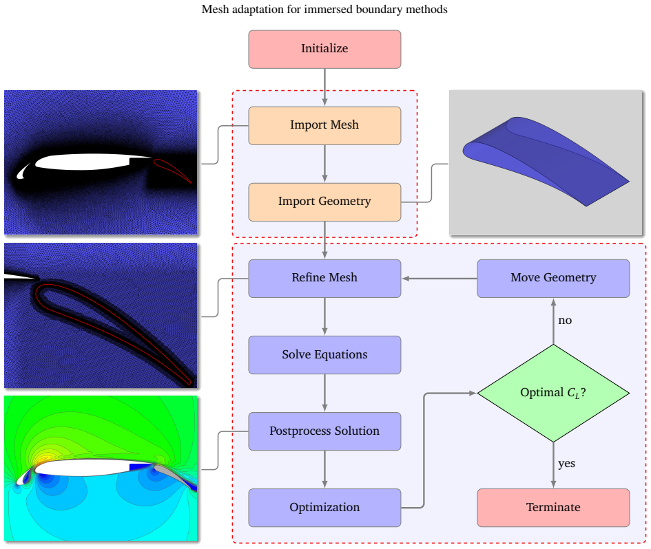
On its own terms, the paper claims that the new mesh-refinement tool makes immersed-boundary volume penalization accurate and efficient on hybrid unstructured meshes. The tool takes a conforming hybrid background mesh, defines a refinement box around where the immersed body will sit, refines elements that overlap the body, and balances refinement so neighboring elements differ by at most a 2:1 level ratio. The resulting locally refined meshes, with hanging nodes and nonconforming faces, are exported for the CFD solver. Validation cases match body-fitted and experimental pressure and force coefficients when the mesh is sufficiently refined: the drag for cylinder and NACA0012 is within a few p
What carries the argument
The load-bearing mechanism is a set of element-splitting conventions plus master–slave interface arrays (TRI4TRI for triangular faces, QUAD4QUAD for quadrilateral faces). Each tetrahedron splits into 8 tetrahedra, each hexahedron into 8 hexahedra, each prism into 8 prisms, and each pyramid into 6 pyramids plus 4 tetrahedra; hanging nodes created by neighboring elements at different refinement levels are encoded through the master/slave arrays. Hash tables and kd-trees make the geometry-overlap detection and face-matching efficient. These interfaces drive the 2:1 balancing step that keeps the mesh locally refined without producing more than one refinement level difference between neighbors. T
Load-bearing premise
The pipeline depends on the CFD solver correctly handling hanging-node, nonconforming faces between neighboring elements after refinement; the paper demonstrates refined meshes but does not show the solver's treatment of nonconforming interfaces.
What would settle it
Take a problem with a known smooth solution and run the same pipeline on a hybrid mesh with a deliberately introduced hanging-node face; if the solver does not converge to the analytical solution at the expected rate, or if a refined mesh with hanging nodes fails to reproduce the body-fitted force coefficient on the same geometry, the central claim fails.
If this is right
- A single body-fitted background mesh can serve a family of configurations: only the changing part, such as a flap, is placed as an immersed body and locally refined.
- Local refinement around immersed surfaces can replace uniform Cartesian refinement, keeping element counts and runtime practical for industrial cases.
- The reported force coefficients (drag for cylinder and NACA0012, lift for the multi-element airfoil) approach full body-fitted and experimental values as the refinement level increases.
- Optimization loops can reuse a pre-refined region that covers all possible positions of the moving component, avoiding a full remesh at each design evaluation.
- Both finite volume and discontinuous Galerkin spatial discretizations can be coupled with the volume-penalization immersed boundary method on the refined hybrid meshes.
Where Pith is reading between the lines
- Beyond the paper: if the CFD solver truly accepts nonconforming faces, this pipeline could be applied to any hybrid mesh with local refinement, not just two-dimensional extrusions; the same splitting conventions should extend to 3-D refinement of complex aircraft components.
- The 2:1 balancing rule is a design choice; one could test whether relaxing it to 4:1 or allowing graded refinement reduces element counts without hurting force predictions, though accuracy would need checking near the immersed surface.
- The optimization example suggests a practical workflow: pre-refine a region large enough to contain all possible flap positions, then move the immersed geometry inside it without remeshing—an implicit cost-saving claim the paper does not quantify directly.
- Because the immersed geometry is refined by surface-overlap, the tool's accuracy will depend on the facet size of the STL representation relative to the mesh; a sensitivity study on facet density would be a natural next test.
Editorial analysis
A structured set of objections, weighed in public.
Referee Report
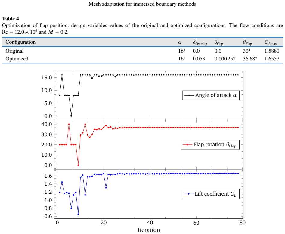
Summary. This manuscript presents a preprocessing tool that refines hybrid unstructured (tetrahedral, hexahedral, prismatic, pyramidal) body-fitted background meshes locally around immersed geometries for use with the CODA CFD solver and an immersed-boundary volume-penalization method. The tool constructs nonconforming hanging-node interfaces, balances refinement to a 2:1 level ratio, and exports an HDF5 mesh that is claimed to be directly usable by the solver. The authors validate the approach on 2D-extruded cases: laminar flow past a cylinder (Re=40), laminar flow past an NACA0012 airfoil (Re=5000), and RANS flow past an MDA30P30N multi-element airfoil (Re=9e6), reporting pressure coefficients and force coefficients in reasonable agreement with body-fitted and experimental references. A further example optimizes flap position in a two-element airfoil with GEMSEO. The central claim is that the refined meshes allow the IBM-equipped CODA solver to simulate flows around immersed components accurately and efficiently by avoiding full remeshing.
Significance. If substantiated, the tool would enable a practically useful workflow: a body-fitted, wall-resolved mesh for a fixed geometry, with changing components (flaps, control surfaces) treated as immersed and locally refined, avoiding costly re-meshing. The paper gives a detailed algorithmic description and validates against independent published data without curve-fitting; the reported coefficient matches (e.g., cylinder Cd≈1.53–1.55 vs. 1.56–1.57 in the literature; fine-mesh MDA30P30N Cl=2.776 vs. 2.876 experiment) are encouraging. However, the strongest claims extend to true three-dimensional hybrid meshes, while every validation case is extruded 2D. Moreover, the pipeline's compatibility with CODA hinges on an unstated assumption about nonconforming-interface support, and key numerical parameters (notably η) are not reported. These gaps weaken the paper in its current form but are addressable.
major comments (5)
- [§4.1, §4.2, Algorithm 1] The refinement deliberately creates hanging nodes and nonconforming faces (Fig. 4, Section 4.1), and Algorithm 1 exports 'the resulting mesh in HDF5 format, compatible with the CFD solver.' Nowhere is it stated or demonstrated that CODA's finite-volume or discontinuous-Galerkin discretizations accept nonconforming interfaces, nor is any conforming step described before export. The reported successful runs are indirect evidence, but the central compatibility claim ('compatible with the CFD solver') is load-bearing and rests on an unverified external capability. Please state explicitly whether CODA supports hanging-node/nonconforming faces, or add a conforming/interface-treatment step, with a reference or a test.
- [§4.2, Algorithms 2 and 4] The element-flagging logic is internally inconsistent. The text preceding Algorithm 4 says an element is flagged when the number of intersecting geometry facets is 'greater than zero,' but Algorithm 4 uses 'if Elem.nFacets > 1.' Algorithm 2 appears to query only a single nearest facet ('Facet←NearestNeighbors(BBox,FacetsBary)') and increments Elem.nFacets by 1, whereas the text says the number of intersecting facets is stored. If the threshold is truly >1, elements crossed by exactly one geometry facet would never be refined, creating gaps in the refined band; if the pseudocode is literal, many overlapping facets are missed. Please clarify the actual implementation and correct the pseudocode, since this is the core of the refinement algorithm.
- [§5 and Eq. (44)] The penalization parameter η is central to the volume-penalization source term (Eq. 44) and is listed as a free parameter, but its numerical value is not reported for any test case (cylinder, NACA0012, MDA30P30N, or optimization). Without η (and the refinement box dimensions), the simulations cannot be reproduced. Please provide the η values and box-region sizes used in each case.
- [Abstract and §5.3] The abstract claims the meshes enable simulations 'in an accurate and efficient manner,' but no efficiency data are reported: no wall-clock times, CPU-hour counts, mesh-generation times, or comparison with the cost of a full body-fitted re-mesh. The fine MDA30P30N IBM mesh has 4,585,591 elements versus 736,472 for the body-fitted mesh, yet the paper does not discuss whether the IBM+refinement workflow is actually cheaper. Please add quantitative efficiency metrics or temper the efficiency claim.
- [§5.1–§5.3 and Conclusions] All validation cases are extruded 2D: the computational domain is a disk extruded one element in the y-direction with symmetry boundary conditions on the front and back faces. The tool's stated capability for genuine three-dimensional hybrid meshes (tetrahedra, pyramids, etc.) is therefore not tested by any three-dimensional case. The conclusions generalize to 3D industrial geometries and mention extensions to 'a billion elements,' but the present results do not substantiate that. Please add at least one truly 3D demonstration or explicitly restrict the scope to 2D-extruded configurations.
minor comments (5)
- [§5.1] Typo: 'vecinity' should be 'vicinity'.
- [§2.2] The turbulence model is repeatedly called 'Spallart–Allmaras'; the correct spelling is 'Spalart–Allmaras'.
- [Figures 8, 10, 12] The legend labels contain garbled characters (e.g., '∝O⌋⊣↕2-BFM'); these should be rendered as 'FV-II-BFM', 'DG-III-IBM', etc.
- [§5.4] The optimization result is presented as 'consistent with a similar optimization workflow with only body-fitted meshes' in the Conclusions, but no comparison data or reference to the companion paper is shown. Please provide evidence or qualify the statement.
- [Algorithm 6] The loop upper bound 'L' is not defined. It should be the current maximum refinement level; please define it explicitly.
Circularity Check
No circular reasoning: the refinement tool is validated against independent body-fitted and experimental data; self-citations are component reuse, not load-bearing derivations.
full rationale
The paper's central claim is that the preprocessing tool refines hybrid unstructured meshes around immersed geometries and that CODA with volume penalization on these meshes reproduces body-fitted and experimental force coefficients. This is not circular: the refinement algorithms (Algorithms 1-7) are defined in terms of element splitting and geometry overlap, not in terms of the output quantities (Cp, Cl, Cd). The validation compares against independent references, including Canuto & Taira [10], Yu & Pantano [67], Crumpton et al. [15], Jawahar & Kamath [26], and Murayama et al. [35], as well as full body-fitted CODA runs. No parameter is fitted to the target coefficients; refinement levels, mesh sizes, and the SA constants are stated independently. The authors' previous volume-penalization implementation [37] is invoked as a component of the workflow, but the present study does not derive its conclusions from that citation; the reported agreement is checkable from the provided tables and figures. The concern that CODA's support for the deliberately created hanging nodes and nonconforming faces is not documented is a real correctness/verifiability risk, not a circularity, because it concerns an external capability assumption rather than an equivalence between output and input.
Axiom & Free-Parameter Ledger
free parameters (4)
- penalization parameter eta =
not reported
- maximum refinement level per case =
5, 8, 4, 14, 7 depending on case
- geometry facet characteristic length =
5e-3, 2.5e-3, 2.0e-3 depending on case
- neighbor search radius factor in Algorithm 2 =
10 times element size
axioms (3)
- domain assumption CODA solver accepts meshes with hanging nodes / nonconforming faces produced by the refinement.
- domain assumption Geometry overlap detection via kd-tree nearest neighbors within 10 times element size is sufficient for all immersed configurations.
- domain assumption The ray-casting mask function correctly classifies inside/outside for the STL surfaces.
read the original abstract
In this work, we describe a new preprocessing tool for mesh adaptation on hybrid unstructured meshes with a target application on immersed boundary methods. The tool has as input an unstructured, hybrid, and conforming mesh generated by an external mesh generation software, and the main goal is to refine this mesh around immersed geometries in such a way that the CFD solver using the immersed boundary method can simulate flow problems in an accurate and efficient manner. The input background mesh can be made of different types of elements, like tetrahedra, hexahedra, prisms, and pyramids, which, unlike Cartesian meshes, permit for a more flexible mesh. Hybrid unstructured meshes enable one to use the immersed boundary technology in a new class of flow problems where the full geometry is decomposed into a fixed geometry part and a changing geometry part. A body-fitted mesh is generated for the fixed geometry while for the changing one is used the immersed boundary method. We simulate several flow problems to test the new meshes, including subsonic flow past a cylinder and subsonic flow past an NACA0012 airfoil, both using finite volume and discontinuous Galerkin methods and solving the Navier--Stokes equations. As an industrial example of our mesh generation, we consider the simulation of a multi-element airfoil: in this case, a mesh generation software generates an unstructured conforming background mesh for the slat and main airfoil, while the flap is placed as immersed geometry in this body-fitted mesh. As accurate and efficient results are sought, this mesh is refined around the flap and then the subsonic flow at high-lift flow conditions is simulated with a finite volume method coupled with an immersed boundary method and using the Reynolds--averaged Navier--Stokes equations. The reported numerical simulations are in good agreement with experimental data.
Figures



Reference graph
Works this paper leans on
-
[1]
Immersed boundary method implemented for the simulationof an external flow on unstructured meshes
Abalakin, I., Zhdanova, N., Kozubskaya, T., 2016. Immersed boundary method implemented for the simulationof an external flow on unstructured meshes. Mathematical Models and Computer Simulations 8, 219–230. doi:10.1134/S2070048216030029
-
[2]
Navier–Stokes computations and experimental comparisons for multielement airfoil configurations
Anderson, W., Bonhaus, D., McGhee, R., Walker, B., 1995. Navier–Stokes computations and experimental comparisons for multielement airfoil configurations. Journal of Aircraft 32, 1246–1253. doi:10.2514/3.46871
-
[3]
On the flexibility of agglomeration based physical space discontinuous Galerkin discretizations
Bassi, F., Botti, L., Colombo, A., Di Pietro, D., Tesini, P., 2012. On the flexibility of agglomeration based physical space discontinuous Galerkin discretizations. Journal of Computational Physics 231, 45–65. doi:10.1016/j.jcp.2011.08.018
-
[4]
Bassi, F., Rebay, S., 1997. A high-order accurate discontinuous finite element method for the numerical solution of the compressible Navier– Stokes equations. Journal of Computational Physics 131, 267–279. doi:10.1006/jcph.1996.5572
arXiv 1997
-
[5]
AerodynamicandFSIanalysisofwindturbineswiththe ALE-VMS and ST-VMS methods
Bazilevs,Y.,Takizawa,K.,Tezduyar,T.,Hsu,M.C.,Kostov,N.,McIntyre,S.,2014. AerodynamicandFSIanalysisofwindturbineswiththe ALE-VMS and ST-VMS methods. Archives of Computational Methods in Engineering 21, 359–398. doi:10.1007/s11831-014-9119-7
-
[6]
Berta,V.,Mignone,A.,Bugli,M.,Mattia,G.,2024. A4th-orderaccuratefinitevolumemethodforidealclassicalandspecialrelativisticMHD based on pointwise reconstructions. Journal of Computational Physics 499, 112701. doi:10.1016/j.jcp.2023.112701
arXiv 2024
-
[7]
Computational Fluid Dynamics: Principles and Applications
Blazek, J., 2015. Computational Fluid Dynamics: Principles and Applications. 3 ed., Elsevier Science, Amsterdam
2015
-
[8]
PHOENIX: MHD spectral code for rotating laboratory and gravitating astrophysical plasmas
Blokland, J.W., van der Holst, B., Keppens, R., Goedbloed, H., 2007. PHOENIX: MHD spectral code for rotating laboratory and gravitating astrophysical plasmas. Journal of Computational Physics 226, 509–533
2007
-
[9]
Boukharfane,R.,Ribeiro,F.,Bouali,Z.,Mura,A.,2018. Acombinedghost-point-forcing/direct-forcingimmersedboundarymethod(IBM) for compressible flow simulations. Computers & Fluids 162, 91–112. doi:10.1016/j.compfluid.2017.11.018
-
[10]
Two-dimensionalcompressibleviscousflowaroundacircularcylinder
Canuto,D.,Taira,K.,2015. Two-dimensionalcompressibleviscousflowaroundacircularcylinder. JournalofFluidMechanics785,349–371. doi:10.1017/jfm.2015.635
-
[11]
Turbulent wall model for immersed boundary methods
Capizzano, F., 2011. Turbulent wall model for immersed boundary methods. AIAA Journal 49, 2367–2381. doi:10.2514/1.J050466
-
[12]
Coupling a wall diffusion model with an immersed boundary technique
Capizzano, F., 2016. Coupling a wall diffusion model with an immersed boundary technique. AIAA Journal 54, 728–734. doi:10.2514/1. J054197
doi:10.2514/1 2016
-
[13]
Automatic generation of locally refined Cartesian meshes: Data management and algorithms
Capizzano, F., 2018. Automatic generation of locally refined Cartesian meshes: Data management and algorithms. International Journal of Numerical Methods in Engineering 113, 789–813. doi:10.1002/nme.5636
-
[14]
Journal of Computational Physics 519, 113441
Constant,B.,Péron,S.,Beaugendre,H.,Benoit,C.,2024.AnimprovedimmersedboundarymethodforturbulentflowsimulationsonCartesian grids: extension of a global geometric approach for thin boundary layers and strong flow incidence. Journal of Computational Physics 519, 113441. doi:10.1016/j.jcp.2024.113441
arXiv 2024
-
[15]
Crumpton,P.,Mackenzie,J.,Morton,K.,1993.CellvertexalgorithmsforthecompressibleNavier–Stokesequations.JournalofComputational Physics 109, 1–15. doi:10.1006/jcph.1993.1194
arXiv 1993
-
[16]
A sharp-interface immersed boundary method for moving objects in compressible viscous flows
De Vanna, F., Picano, F., Benini, E., 2020. A sharp-interface immersed boundary method for moving objects in compressible viscous flows. Computers & Fluids 201, 104415. doi:10.1016/j.compfluid.2019.104415
arXiv 2020
-
[17]
Numerical simulation of fluid-structure interaction with the volume penalization method
Engels, T., Kolomenskiy, D., Schneider, K., Sesterhenn, J., 2015. Numerical simulation of fluid-structure interaction with the volume penalization method. Journal of Computational Physics 281, 96–115. doi:10.1016/j.jcp.2014.10.005
-
[18]
CombinedImmersed-BoundaryFinite-DifferenceMethodsforThree-Dimensional Complex Flow Simulations
Fadlun,E.,Verzicco,R.,Orlandi,P.,MohdYusof,J.,2000. CombinedImmersed-BoundaryFinite-DifferenceMethodsforThree-Dimensional Complex Flow Simulations. Journal of Computational Physics 161, 35–60. doi:10.1006/jcph.2000.6484
arXiv 2000
-
[19]
Gallard, F., Vanaret, C., Guenot, D., Gachelin, V., Lafage, R., Pauwels, B., Barjhoux, P.J., Gazaix, A., 8–12 January 2018. GEMS: A Python library for automation of multidisciplinary design optimization process generation, in: Proceedings of the 2018 AIAA/ASCE/AHS/ASC Structures, Structural Dynamics, and Materials Conference, Kissimmee, Florida, USA. doi:...
-
[20]
Gmsh: A 3-D finite element mesh generator with built-in pre- and post-processing facilities
Geuzaine, C., Remacle, J.F., 2009. Gmsh: A 3-D finite element mesh generator with built-in pre- and post-processing facilities. International Journal for Numerical Methods in Engineering 79, 1309–1331. doi:10.1002/nme.2579
doi:10.1002/nme.2579 2009
-
[21]
Asharpinterfaceimmersedboundarymethodforcompressibleviscousflows
Ghias,R.,Mittal,R.,Dong,H.,2007. Asharpinterfaceimmersedboundarymethodforcompressibleviscousflows. JournalofComputational Physics 225, 528–553. doi:10.1016/j.jcp.2006.12.007
-
[22]
Modeling a no-slip flow boundary with an external force field
Goldstein, D., Handler, R., Sirovich, L., 1993. Modeling a no-slip flow boundary with an external force field. Journal of Computational Physics 105, 354–366. doi:10.1006/jcph.1993.1081
arXiv 1993
-
[23]
Immersed methods for fluid-structure interaction
Griffith, B., Patankar, N., 2020. Immersed methods for fluid-structure interaction. Annual Review of Fluid Mechanics 52, 421–448. doi:10.1146/annurev-fluid-010719-060228
-
[24]
AghostcellmethodforturbulentcompressibleviscousflowsonadaptiveCartesiangrids
Hu,O.,Zhao,N.,Liu,J.,2013. AghostcellmethodforturbulentcompressibleviscousflowsonadaptiveCartesiangrids. ProcediaEngineering 67, 241–249. doi:10.1016/j.proeng.2013.12.023
-
[25]
Immersed boundary technique for turbulent flow simulations
Iaccarino, G., Verzicco, R., 2003. Immersed boundary technique for turbulent flow simulations. Applied Mechanics Reviews 56, 331–347. doi:10.1115/1.1563627
-
[26]
A high-resolution procedure for Euler and Navier-–Stokes computations on unstructured grids
Jawahar, P., Kamath, H., 2000. A high-resolution procedure for Euler and Navier-–Stokes computations on unstructured grids. Journal of Computational Physics 164, 165–203. doi:10.1006/jcph.2000.6596
arXiv 2000
-
[27]
Comparative results from a CFD challenge over a 2D three-element high-lift airfoil
Klausmeyer, S., Lin, J., 1997. Comparative results from a CFD challenge over a 2D three-element high-lift airfoil. NASA Technical Memorandum NASA-TM-112858. NASA Langley Research Center. Hampton, Virginia, USA
1997
-
[28]
DLR project Digital-X: towards virtual aircraft design and flight testing based on high-fidelity methods
Kroll,N.,AbuZurayk,M.,Dimitrov,D.,Franz,T.,Führer,T.,Gerhold,T.,Görtz,S.,Heinrich,R.,Ilic,C.,Jepsen,J.,Jägersküpper,J.,Kruse, Page 29 of 31 Mesh adaptation for immersed boundary methods M., Krumbein, A., Langer, S., Liu, D., Liepelt, R., Reimer, L., Ritter, M., Schwöppe, A., Scherer, J., Spiering, F., Thormann, R., Togiti, V., Vollmer, D., Wendisch, J.H.,...
2016
-
[29]
ABrinkmanpenalizationmethodforcompressibleflowsincomplexgeometries
Liu,Q.,Vasilyev,O.,2007. ABrinkmanpenalizationmethodforcompressibleflowsincomplexgeometries. JournalofComputationalPhysics 227, 946–966. doi:10.1016/j.jcp.2007.07.037
-
[30]
Luo, C., Bi, L., Meng, S., Gao, H., Yuan, X., Tang, Z., 2025. A novel algorithm for fluid dynamics simulation with cell-adaptive Cartesian grids and immersed boundary method. Physics of Fluids 37, 046122. doi:10.1063/5.0262707
-
[31]
Luo, H., Xia, Y., Li, S., Nourgaliev, R., Cai, C., 2012. A Hermite WENO reconstruction-based discontinuous Galerkin method for the Euler equations on tetrahedral grids. Journal of Computational Physics 231, 5489–5503. doi:10.1016/j.jcp.2012.05.011
-
[32]
Numerical methods for fluid–structure interaction models of aortic valves
Marom, G., 2015. Numerical methods for fluid–structure interaction models of aortic valves. Archives of Computational Methods in Engineering 22, 595–620. doi:10.1007/s11831-014-9133-9
-
[33]
EnhancedstrategyforadaptiveCartesiangridgenerationwitharbitrarilycomplex 3D geometry
Meng,S.,Zhou,D.,Yuan,X.,Li,X.,Chen,H.,Bi,L.,2022. EnhancedstrategyforadaptiveCartesiangridgenerationwitharbitrarilycomplex 3D geometry. Advances in Engineering Software 174, 103304. doi:10.1016/j.advengsoft.2022.103304
arXiv 2022
-
[34]
Mittal, R., Iaccarino, G., 2005. Immersed Boundary Methods. Annual Review of Fluid Mechanics 37, 239–261. doi:10.1146/annurev. fluid.37.061903.175743
arXiv 2005
-
[35]
Murayama, M., Nakakita, K., Yamamoto, K., Ura, H., Ito, Y., Choudhari, M., 16–20 June 2014. Experimental study on slat noise from 30P30N three-element high-lift airfoil at JAXA Hard-Wall Lowspeed Wind Tunnel, in: Proceedings of the 20th AIAA/CEAS Aeroacoustics Conference, Atlanta, Georgia, USA. doi:10.2514/6.2014-2080
-
[36]
Núñez-de la Rosa, J., Ferrer, E., Valero, E., 2026a. Mesh adaptation on hybrid unstructured meshes for immersed boundary methods with applications to industrial aerodynamics. Engineering Proceedings 133, 62. doi:10.3390/engproc2026133001
-
[37]
Núñez-de la Rosa, J., Huergo, D., Lodares, D., Shrestha, S., Guerra, J., Florenciano, J., Ferrer, E., Valero, E., 2025. Implementation of immersed boundaries via volume penalization in the industrial aeronautical computational fluid dynamics solver CODA. Engineering with Computers doi:10.1007/s00366-025-02119-x
-
[38]
Núñez-de la Rosa, J., Mateo, A., Ferrer, E., Valero, E., 2026b. Optimization of the flap position of a high-lift multi-element airfoil using a body-fitted mesh along with immersed boundary methods. Engineering Proceedings 133, 61. doi:10.3390/engproc2026133002
-
[39]
Núñez-de la Rosa, J., Munz, C.D., 2016a. XTROEM-FV: a new code for computational astrophysics based on very high order finite-volume methods–i.Magnetohydrodynamics. MonthlyNoticesoftheRoyalAstronomicalSociety455,3458–3479. doi:10.1093/mnras/stv2531
-
[40]
Núñez-de la Rosa, J., Munz, C.D., 2016b. XTROEM-FV: a new code for computational astrophysics based on very high order finite- volume methods – ii. Relativistic hydro- and magnetohydrodynamics. Monthly Notices of the Royal Astronomical Society 460, 535–559. doi:10.1093/mnras/stw999
-
[41]
Hybrid DG/FV schemes for magnetohydrodynamics and relativistic hydrodynamics
Núñez-de la Rosa, J., Munz, C.D., 2018. Hybrid DG/FV schemes for magnetohydrodynamics and relativistic hydrodynamics. Computer Physics Communications 222, 113–135. doi:10.1016/j.cpc.2017.09.026
-
[42]
Cut-elementbasedimmersedboundarymethodformovinggeometriesincompressible liquid flows with cavitation
Örley,F.,Pasquariello,V.,Hickel,S.,Adams,N.,2015. Cut-elementbasedimmersedboundarymethodformovinggeometriesincompressible liquid flows with cavitation. Journal of Computational Physics 283, 1–22. doi:10.1016/j.jcp.2014.11.028
-
[43]
Cartesianmeshadaptation:immersedboundarymethodbasedonhigh-order discontinuous Galerkin method
Ouyang,W.,Huang,J.,Wang,T.,An,W.,Liu,X.,Lyu,H.,2024. Cartesianmeshadaptation:immersedboundarymethodbasedonhigh-order discontinuous Galerkin method. Physics of Fluids 36, 096139. doi:10.1063/5.0223305
-
[44]
Engineering with Computers 37, 2419–2437
Péron,S.,Benoit,C.,Renaud,T.,Mary,I.,2021.AnimmersedboundarymethodonCartesianadaptivegridsforthesimulationofcompressible flows around arbitrary geometries. Engineering with Computers 37, 2419–2437. doi:10.1007/s00366-020-00950-y
-
[45]
Flow patterns around heart valves: a numerical method
Peskin, C., 1972. Flow patterns around heart valves: a numerical method. Journal of Computational Physics 10, 252–271. doi:10.1016/ 0021-9991(72)90065-4
1972
-
[46]
Qi, X., Wang, Z., Zhu, J., Tian, L., Zhao, N., 2024. High-order discontinuous Galerkin method with immersed boundary treatment for compressible flows on parallel adaptive Cartesian grids. Physics of Fluids 36, 116139. doi:10.1063/5.0238605
-
[47]
A boundary condition-enforced immersed boundary method for compressible viscous flows
Qiu, Y., Shu, C., Wu, J., Sun, Y., Yang, L., Guo, T., 2016. A boundary condition-enforced immersed boundary method for compressible viscous flows. Computers & Fluids 136, 104–113. doi:10.1016/j.compfluid.2016.06.004
-
[48]
Progress in high-lift aerodynamic calculations
Rogers, S., 1994. Progress in high-lift aerodynamic calculations. Journal of Aircraft 31, 1244–1251. doi:10.2514/3.46642
-
[49]
Rogers, S., Menter, F., Durbin, P., Mansour, N., 10–13 January 1994. A comparison of turbulence models in computing multi-element airfoil flows, in: Proceedings of the 32nd AIAA Aerospace Sciences Meeting and Exhibit, Reno, Nevada, USA. doi:10.2514/6.1994-291
-
[50]
Predictionofhigh-liftflowsusingturbulentclosuremodels
Rumsey,C.,Gatski,T.,Ying,S.,Bertelrud,A.,1998. Predictionofhigh-liftflowsusingturbulentclosuremodels. AIAAJournal36,765–774. doi:10.2514/2.435
-
[51]
Schneider, K., 2015. Immersed boundary methods for numerical simulation of confined fluid and plasma turbulence in complex geometries: a review. Journal of Plasma Physics 81, 435810601. doi:10.1017/S0022377815000598
-
[52]
Analysis of the Common Research Model using structured and unstructured meshes
Sclafani, A., Vassberg, J., Winkler, C., Dorgan, A., Mani, M., Olsen, M., Coder, J., 2014. Analysis of the Common Research Model using structured and unstructured meshes. Journal of Aircraft 51, 1223–1243. doi:10.2514/1.C032411
-
[53]
Shao, J.Y., Shu, C., Chew, Y.T., 2013. Development of an immersed boundary-phase field-lattice Boltzmann method for Neumann boundary condition to study contact line dynamics. Journal of Computational Physics 234, 8–32. doi:10.1016/j.jcp.2012.08.040
-
[54]
Immersed boundary methods for simulating fluid-structure interaction
Sotiropoulos, F., Yang, X., 2014. Immersed boundary methods for simulating fluid-structure interaction. Progress in Aerospace Sciences 65, 1–21. doi:10.1016/j.paerosci.2013.09.003
-
[55]
HighReynoldsnumber,multielementairfoilflowfieldmeasurements
Spaid,F.,2000. HighReynoldsnumber,multielementairfoilflowfieldmeasurements. JournalofAircraft37,499–507. doi:10.2514/2.2626
-
[56]
NASA Langley Research Center
Swanson,R.,Langer,S.,2016.ComparisonofNACA0012laminarflowsolutions:structuredandunstructuredgridmethods.NASATechnical Memorandum NASA-TM-2016-219003. NASA Langley Research Center. Hampton, Virginia, USA
2016
-
[57]
Near-wall modification of Spalart–Allmaras turbulence model for immersed boundary method
Tamaki, Y., Harada, M., Imamura, T., 2017. Near-wall modification of Spalart–Allmaras turbulence model for immersed boundary method. AIAA Journal 55, 3027–3039. doi:10.2514/1.J055824
-
[58]
A ghost-cell immersed boundary method for flow in complex geometry
Tseng, Y.H., Ferziger, J., 2003. A ghost-cell immersed boundary method for flow in complex geometry. Journal of Computational Physics Page 30 of 31 Mesh adaptation for immersed boundary methods 192, 593–623. doi:10.1016/j.jcp.2003.07.024
-
[59]
ASharpInterfaceCartesianGridMethodforSimulatingFlowswithComplex Moving Boundaries
Udaykumar,H.,Mittal,R.,Rampunggoon,P.,Khanna,A.,2001. ASharpInterfaceCartesianGridMethodforSimulatingFlowswithComplex Moving Boundaries. Journal of Computational Physics 174, 345–380. doi:10.1006/jcph.2001.6916
arXiv 2001
-
[60]
Valarezo, W., 6–8 July 1992. High-lift testing at high Reynolds numbers, in: Proceedings of the 17th AIAA Aerospace Ground Testing Conference, Nashville, Tennessee, USA. doi:10.2514/6.1992-3986
-
[61]
Valarezo, W., Dominik, C., McGhee, R., Goodman, W., Paschal, K., 23–25 September 1991. Multi-element airfoil optimization for maximum lift at high Reynolds numbers, in: Proceedings of the 9th AIAA Applied Aerodynamics Conference, Baltimore, Maryland, USA. doi:10.2514/6.1991-3332
-
[62]
Immersedboundarymethods:historicalperspectiveandfutureoutlook
Verzicco,R.,2023. Immersedboundarymethods:historicalperspectiveandfutureoutlook. AnnualReviewofFluidMechanics55,129–155. doi:10.1146/annurev-fluid-120720-022129
-
[63]
AircraftsimulationsusingthenewCFDsoftwarefrom ONERA, DLR, and Airbus
Volpiani,P.,Chapelier,J.B.,Schwöppe,A.,Jägersküpper,J.,Champagneux,S.,2024. AircraftsimulationsusingthenewCFDsoftwarefrom ONERA, DLR, and Airbus. Journal of Aircraft 61, 857–869. doi:10.2514/1.C037506
-
[64]
Wang, Y., Shu, C., Teo, C.J., Wu, J., 2015. An immersed boundary-lattice Boltzmann flux solver and its applications to fluid-structure interaction problems. Journal of Fluids and Structures 54, 440–465. doi:10.1016/j.jfluidstructs.2014.12.003
-
[65]
Wang, Z., Sun, X., 2020. Adaptive mesh refinement for simulating fluid-structure interaction using a sharp interface immersed boundary method. International Journal of Numerical Methods in Engineering 92, 1890–1913. doi:10.1002/fld.4853
-
[66]
Wu, W., Min, Y., Han, X., Ma, Y., Yan, Z., Deng, X., 2023. Self-adaptive turbulence eddy simulation with a high-order finite differencing method for high Reynolds number complex flows. Aerospace Science and Technology 141, 108562. doi:10.1016/j.ast.2023.108562
arXiv 2023
-
[67]
Animmersed boundarymethod withimplicitbody forcefor compressibleviscous flow
Yu,H., Pantano,C., 2022. Animmersed boundarymethod withimplicitbody forcefor compressibleviscous flow. Journalof Computational Physics 459, 111125. doi:10.1016/j.jcp.2022.111125. Page 31 of 31
arXiv 2022
discussion (0)
Sign in with ORCID, Apple, or X to comment. Anyone can read and Pith papers without signing in.