REVIEW 4 major objections 5 minor 22 references
Toward Geometry-Scalable Whole-Body Touch for Humanoids: A 3D-Printed Conformal EIT Skin
T0 review · 4 major / 5 minor · reviewed 2026-08-04 · deepseek-v4-flash
Pith's one-line read A 3D-printed conductive skin can localize touch on curved robot surfaces to about 6 mm.
desk verdict Solid fabrication contribution with a genuinely useful design-space study; the headline curved-surface number is honest but not yet a fixed-force validation. read the letter →
The pith
A machine-rendered reading of the paper's core claim, the machinery that carries it, and where it could break.
The reading
What carries the argument
The central object is the layered EIT sensing stack: a high-resistance flexible conductive TPU sensing layer (R) combined with low-resistance contact-enhancement patches (r, with R >> r). Touch increases local interfacial coupling, producing a conductivity perturbation reconstructed by a one-step Gauss-Newton solver applied to boundary voltage changes. The resistance ratio R >> r is what makes the perturbation visible; porosity and thinness of the TPU layer amplify sensitivity, and the precomputed reconstruction matrix keeps the inverse fast enough for real-time deployment.
What would settle it
Run the curved U-shaped sensor at a single fixed force (e.g., 5 N) across all 18 positions with an instrumented indenter and machine-measured ground truth; if the mean localization error exceeds about 15 mm, the 6 mm claim does not generalize to force-controlled contact.
Extended reading notes
Core claim
The central claim is that electrical impedance tomography over a layered, 3D-printed conductive sensing domain can recover the position of a single contact on both flat and curved surfaces at millimeter-scale accuracy. The sensing layer is a porous conductive TPU sheet; contact presses a low-resistance fabric patch into it, locally increasing coupling and changing boundary voltages. A linearized one-step Gauss-Newton solver, with the reconstruction matrix precomputed offline, converts those voltage changes into a conductivity map, and a thresholded weighted centroid gives the touch position. On the planar prototype the mean error is 7±3.5 mm at moderate loading (36 samples); on the U-shaped
Load-bearing premise
The headline accuracy assumes every touch is pressed hard enough (a few newtons) to produce a stable EIT response; at light fixed-force contacts the planar error jumps to 25±30 mm, and the curved-surface numbers were collected with indentation adjusted per position to obtain that stable response.
Editorial extensions
If this is right
- Humanoid skins could be printed directly from CAD geometry of a body part, replacing hand-tailored taxel arrays with a continuous sensing layer.
- A single sensor stack works across planar and curved geometries; the U-shaped prototype is direct evidence of geometry transferability.
- Contact localization at roughly 6–7 mm does not require machine learning, only a calibrated linearized EIT solver.
- The sensing principle is force-sensitive: the reconstructed peak response rises with force and saturates around 12 N, so force estimation is feasible with position-dependent calibration.
- Multi-contact detection is possible, though spatial resolution is limited by the diffusive nature of EIT, making nearby contacts blur together.
Reading between the lines
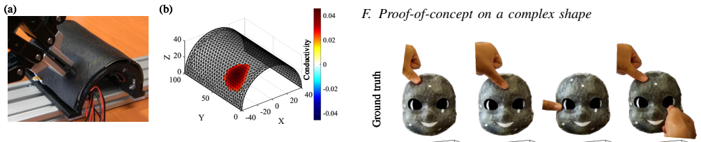
- The freeform face-shaped demonstration is qualitative; extending the 6 mm accuracy to arbitrary double-curved surfaces would require a thinner printable sensing layer than the thicker substitute used in that prototype, so a manufacturability gap remains.
- Because low-force contacts give 25±30 mm error on the flat sensor, practical deployment will need either a minimum-contact-force assumption or a force-dependent reconstruction stage.
- The same layered geometry could be modeled with an anisotropic conductivity tensor for curved shells, potentially improving accuracy on non-developable surfaces without changing the fabrication.
- If the reconstruction matrix is precomputed from the CAD model, the pipeline naturally extends to automated geometry-to-sensor generation for whole-body coverage.
Editorial analysis
A structured set of objections, weighed in public.
Referee Report
Summary. The manuscript proposes a conformal 3D-printed electrical impedance tomography (EIT) tactile skin consisting of a flexible conductive TPU sensing layer, printed structural layers, and low-resistance conductive fabric contact-enhancement patches. Contact localization is performed with a one-step Gauss–Newton solver and a thresholded weighted-centroid estimator, with no supervised post-processing. Electromechanical characterization identifies patch conductivity, sensing-layer thickness, and porosity as dominant design factors. Quantitative experiments on a planar sensor report 25±30 mm mean error at low loading (levels 1–3), 7±3.5 mm at an intermediate loading level (level 6, 36 valid samples), and 6±3 mm at high loading (levels 11–13). On a curved U-shaped sensor the authors report 6±4 mm mean error over 18 contact positions. A qualitative iCub-face prototype demonstrates feasibility on a freeform geometry. The central claim is that the proposed fabrication and reconstruction pipeline transfers across geometries with millimeter-scale localization accuracy.
Significance. If the headline curved-surface result is robust, the work would be a meaningful step toward large-area, geometry-scalable tactile skin: it removes the need for dense taxels, uses a printable conductive layer, avoids learning-based post-processing, and shows a unified reconstruction pipeline for planar and curved sensors. The paper is also honest in disclosing the strong force dependence of the planar result. However, the central geometry-scalability claim is currently not separable from the contact-force protocol: the curved experiment explicitly adjusts indentation per position to obtain a stable response, while the planar data show that localization error varies from 25±30 mm to 6±3 mm with force. The reported 6±4 mm curved result should therefore be treated as a feasibility demonstration under favorable, position-dependent contact conditions, not as a controlled comparison at matched force. With additional force-controlled or fixed-indentation experiments and a reproducible set of reconstruction parameters, the claim could become load-bearing.
major comments (4)
- [Section III.E, Fig. 12] The 6±4 mm mean localization error on the curved sensor is confounded by force. The text states: 'The indentation was adjusted to obtain a stable reconstruction response, rather than to enforce the same contact force at all positions.' Planar data in Section III.B (Fig. 8a) show strong force dependence: 25±30 mm at loading levels 1–3 versus 6±3 mm at levels 11–13. Therefore, choosing indentation per position to stabilize the reconstruction can select favorable force/SNR conditions for each point, making the 6 mm claim a property of the tuning protocol rather than of geometry transfer alone. Please report the actual force or indentation at each of the 18 positions, or run a fixed-indentation / fixed-force comparison on both planar and curved sensors.
- [Section II.C, Eq. (7)] The ground-truth contact position p_gt is defined as the 'manually measured contact location on the sensor surface.' On a U-shaped shell with 40 mm radius, manual contact-point estimation uncertainty is not reported and is plausibly comparable to the claimed errors (1.5–14.4 mm). Without an instrumented ground-truth method or a repeated-measurement reproducibility study, the error floor of the localization metric is not established. Please describe the manual measurement procedure and quantify its repeatability.
- [Section II.B and II.C, Eqs. (2) and (3)] The reconstruction is governed by the regularization hyperparameter λ in Eq. (2) and the threshold ratio α in Eq. (3), but neither value is reported anywhere in the paper. These parameters directly control the localization output: λ determines the smoothness/amplitude of the reconstructed conductivity change, and α determines which elements survive thresholding before centroid computation. Without these values, the reported localization numbers are not reproducible. Please provide the values used and, ideally, a sensitivity analysis over a reasonable range.
- [Section III.B, Fig. 8(b)] The planar headline result is reported as '7±3.5 mm over 36 valid contact samples.' The term 'valid' is never defined, and no information is given about how many total samples were attempted or how many were excluded. If samples were discarded because the reconstruction was poor or the peak response was weak, the reported mean is optimistically biased. Please define the validity criterion and report all trials, including failures, together with per-position errors.
minor comments (5)
- [Abstract and Section III.E] The abstract reports 'a mean localization error of 6 mm,' while the body reports '6±4 mm.' Please use the range in the abstract for consistency and to avoid overstating precision.
- [Fig. 8 caption] The caption contains 'approximately 1.5 ˜N to 16 ˜N'; the tilde before 'N' is likely a typographical artifact. It should read 'approximately 1.5 N to 16 N.'
- [Section II.C, Eq. (6)] In Eq. (6), the variables δσ_i, V_i, and c_i are not explicitly defined before use. Define them as the reconstructed conductivity change, element volume, and element centroid of the i-th tetrahedral element.
- [Section III.F] The sentence 'an soft cover layer was printed using Stereolithography' contains a grammar error ('an soft') and should be clarified: the rest of the paper describes FDM printing, so the switch to SLA for the face geometry should be explained more explicitly.
- [Section III.B] The 36 valid samples are said to be collected at 'loading level 6,' but the paper does not state how many contact positions were used or how many replicates per position. Please specify the experimental design (number of positions × repetitions) so the reader can interpret the sample size.
Circularity Check
No significant circularity: localization results are measured against external ground truth; self-citations are not load-bearing.
full rationale
The paper's central quantitative claims are empirical measurements, not derived predictions that reduce to their inputs. Planar localization error (7±3.5 mm at loading level 6, Fig. 8) and curved-surface error (6±4 mm over 18 positions, Sec. III.E) are computed as Euclidean distances between EIT-reconstructed weighted centroids and manually defined ground-truth contact locations (Eqs. 5–7). The reconstruction chain uses a standard one-step Gauss–Newton EIT solver (Eq. 2) with external methodological references [20,21] and EIDORS [21]; no fitted parameter is renamed as a prediction. The self-citations present in the paper are not load-bearing: [9] supplies acquisition-board hardware details, and [17] is a disclosed workshop precursor of the curved experiment. Neither is an unverified theorem on which the conclusions rest. The manuscript explicitly discloses the main experimental caveat in Sec. III.E: indentation on the curved sensor was adjusted to obtain a stable reconstruction response rather than enforcing a fixed force, and in Sec. III.C it states that accurate force estimation would require calibration or learning. These are validity and generalization limitations, not circular construction. Under the provided criteria, there is no exhibited Eq.-to-Eq. reduction or fitted-parameter-as-prediction step, so the appropriate finding is no significant circularity.
Assumptions & free parameters
free parameters (3)
- Threshold ratio alpha (Eq. 3) =
not reported
- Regularization hyperparameter lambda (Eq. 2) =
not reported
- Per-geometry fabrication parameters (sensing-layer thickness, porosity, patch layout) =
0.2-0.6 mm thickness; 26.96% and 38.40% porosity for planar vs curved; 0.8 mm solid layer for face demo
assumptions (4)
- standard math Linearized EIT forward model: Delta V = J Delta sigma (small perturbation approximation holds)
- domain assumption Contact manifests as a localized volumetric conductivity increase in the sensing layer
- domain assumption The EIDORS finite-element model matches the fabricated sensor geometry
- domain assumption Two-terminal measurements from 16 electrodes yield 120 independent voltage readings per frame
Cite this review
Pith. "Pith review of Toward Geometry-Scalable Whole-Body Touch for Humanoids: A 3D-Printed Conformal EIT Skin." pith.science (2026). https://pith.science/paper/G3LEGICE
@misc{pith2026260802080,
  author       = {Pith},
  title        = {Pith review of: Toward Geometry-Scalable Whole-Body Touch for Humanoids: A 3D-Printed Conformal EIT Skin},
  year         = {2026},
  howpublished = {\url{https://pith.science/paper/G3LEGICE}},
  note         = {Machine review of arXiv:2608.02080}
}
read the original abstract
Whole-body tactile sensing is a prerequisite for humanoids that operate in contact-rich human environments, but conventional taxel arrays scale poorly with surface area, wiring complexity, and robot-specific curvature. We present a conformal electrical impedance tomography tactile skin fabricated through a geometry-adaptable additive-manufacturing workflow. A flexible conductive TPU layer forms a continuous sensing domain, while contact-induced coupling with conductive patches produces boundary voltage changes that are reconstructed using a one-step Gauss-Newton EIT solver. We first characterize the electromechanical design space of the layered structure and show that low-resistance contact-enhancement patches and a porous conductive TPU sensing layer improve sensitivity while preserving printability. We then validate contact localization on a planar prototype, a curved U-shaped prototype, and a qualitative iCub-face-shaped geometry. The curved sensor achieves a mean localization error of 6 mm over 18 contact positions without supervised post-processing. These results suggest that additively manufactured tomographic skins can reduce the morphology-specific redesign burden for humanoid tactile coverage and provide a practical route toward large-area contact sensing for human-centered deployment.
Figures


Figures from the paper (5 more)



Reference graph
Works this paper leans on
-
[1]
Dexforce: Extracting force-informed actions from kinesthetic demonstrations for dexterous manipulation,
C. Chen, Z. Yu, H. Choi, M. Cutkosky, and J. Bohg, “Dexforce: Extracting force-informed actions from kinesthetic demonstrations for dexterous manipulation,”IEEE Robotics and Automation Letters, vol. 10, no. 6, pp. 6416–6423, 2025
2025
-
[2]
Large-scale integrated flexible tactile sensor array for sensitive smart robotic touch,
Z. Zhao, J. Tang, J. Yuan, Y . Li, Y . Dai, J. Yao, Q. Zhang, S. Ding, T. Li, R. Zhang,et al., “Large-scale integrated flexible tactile sensor array for sensitive smart robotic touch,”ACS nano, vol. 16, no. 10, pp. 16 784–16 795, 2022
2022
-
[3]
A comprehensive realization of robot skin: Sensors, sensing, control, and applications,
G. Cheng, E. Dean-Leon, F. Bergner, J. R. G. Olvera, Q. Leboutet, and P. Mittendorfer, “A comprehensive realization of robot skin: Sensors, sensing, control, and applications,”Proceedings of the IEEE, vol. 107, no. 10, pp. 2034–2051, 2019
-
[4]
Tacsuit: A wear- able large-area, bioinspired multimodal tactile skin for collaborative robots,
Y . Zhou, J. Zhao, P. Lu, Z. Wang, and B. He, “Tacsuit: A wear- able large-area, bioinspired multimodal tactile skin for collaborative robots,”IEEE Transactions on Industrial Electronics, vol. 71, no. 2, pp. 1708–1717, 2023
2023
-
[5]
Graph-structured super-resolution for geometry-generalized tomographic tactile sensing: Application to humanoid faces,
H. Park, W. Kim, S. Jeon, Y . Na, and J. Kim, “Graph-structured super-resolution for geometry-generalized tomographic tactile sensing: Application to humanoid faces,”IEEE Transactions on Robotics, vol. 41, pp. 558–572, 2024
2024
-
[6]
A biomimetic elastomeric robot skin using electrical impedance and acoustic tomography for tactile sensing,
M. Yang, “A biomimetic elastomeric robot skin using electrical impedance and acoustic tomography for tactile sensing,”Science Robotics, vol. 7, no. 67, p. eabm7187, 2022
2022
-
[7]
A body-scale robotic skin using distributed multimodal sensing modules: Design, evaluation, and application,
M. J. Yang, H. Chung, Y . Kim, K. Park, and J. Kim, “A body-scale robotic skin using distributed multimodal sensing modules: Design, evaluation, and application,”IEEE Transactions on Robotics, vol. 41, pp. 96–109, 2025
2025
-
[8]
A large-area robotic skin for intelligent tactile interaction of collaborative robots,
W. Zheng, D. Guo, W. Yang, and H. Liu, “A large-area robotic skin for intelligent tactile interaction of collaborative robots,”IEEE/ASME Transactions on Mechatronics, 2025
2025
Show all 22 references
-
[9]
A large- area flexible tactile sensor for multi-touch and force detection using electrical impedance tomography,
H. Chen, X. Yang, P. Wang, J. Geng, G. Ma, and X. Wang, “A large- area flexible tactile sensor for multi-touch and force detection using electrical impedance tomography,”IEEE Sensors Journal, vol. 22, no. 7, pp. 7119–7129, 2022
2022
-
[10]
Wireless pressure monitoring system utilizing a 3D-printed origami pressure sensor array,
H. Moeinnia, D. J. Agron, C. Ganzert, L. Schubert, and W. S. Kim, “Wireless pressure monitoring system utilizing a 3D-printed origami pressure sensor array,”npj Flexible Electronics, vol. 8, no. 1, p. 21, 2024
2024
-
[11]
MetaSense: Integrating sensing capabilities into mechanical metamaterial,
J. Gong, O. Seow, C. Honnet, J. Forman, and S. Mueller, “MetaSense: Integrating sensing capabilities into mechanical metamaterial,” in The 34th Annual ACM Symposium on User Interface Software and Technology, 2021, pp. 1063–1073
2021
-
[12]
Enhancing 3D-printed piezoresistive sensors: An investigation into process parameters, sensor geometries and materials selection,
S. Imranuddin, A. Singh, G. Stano, S. A. I. Ovy, G. Percoco, and Y . Tadesse, “Enhancing 3D-printed piezoresistive sensors: An investigation into process parameters, sensor geometries and materials selection,”IEEE Sensors Journal, vol. 25, no. 8, pp. 13 063–13 072, 2025
2025
-
[13]
Fully additively 3D manufactured conductive deformable sensors for pressure sensing,
C. Massaroni, L. Vitali, D. Lo Presti, S. Silvestri, and E. Schena, “Fully additively 3D manufactured conductive deformable sensors for pressure sensing,”Advanced Intelligent Systems, vol. 6, no. 8, p. 2300901, 2024
2024
-
[14]
Design, mapping, and contact anticipation with 3d- printed whole-body tactile and proximity sensors,
C. Kohlbrenner, A. Soukhovei, C. Escobedo, N. Nechyporenko, and A. Roncone, “Design, mapping, and contact anticipation with 3d- printed whole-body tactile and proximity sensors,” in2026 IEEE International Conference on Robotics and Automation (ICRA), 2026
2026
-
[15]
Design and modelling of electrical impedance tomography-based 3d- printed patterned soft tactile skins,
Y . Huang, D. Hardman, C. Bascucci, F. Clemens, and T. G. Thuruthel, “Design and modelling of electrical impedance tomography-based 3d- printed patterned soft tactile skins,” in2025 IEEE 8th International Conference on Soft Robotics (RoboSoft). IEEE, 2025, pp. 1–6
2025
-
[16]
Investigating a novel 3D-printed electrical impedance tomography sensor for monitoring the interaction pressure on a customized physical interface in wearable robots,
H. Chen, Z. Wang, K. Langlois, P. Mohamadi, H. Tian, T. Verstraten, and B. Vanderborght, “Investigating a novel 3D-printed electrical impedance tomography sensor for monitoring the interaction pressure on a customized physical interface in wearable robots,”Measurement, vol. 25...
2026
-
[17]
A 3d-printed electrical impedance tomography tactile sensor for scalable coverage,
H. Chen, C. Kohlbrenner, J. Kubik, L. Rustler, A. Dickhans, A. Ron- cone, H. Lee, and M. Hoffmann, “A 3d-printed electrical impedance tomography tactile sensor for scalable coverage,” Workshop on To- wards Large-Area Tactile Sensing Skins: From Scalable Materials to Embodied R...
2026
-
[18]
Internal array electrodes improve the spatial resolution of soft tactile sensors based on electrical resistance tomography,
H. Lee, K. Park, J. Kim, and K. J. Kuchenbecker, “Internal array electrodes improve the spatial resolution of soft tactile sensors based on electrical resistance tomography,” in2019 International Conference on Robotics and Automation (ICRA). IEEE, 2019, Conference Proceedings,...
2019
-
[19]
Temporal image reconstruc- tion in electrical impedance tomography,
A. Adler, T. Dai, and W. R. Lionheart, “Temporal image reconstruc- tion in electrical impedance tomography,”Physiological measurement, vol. 28, no. 7, p. S1, 2007
2007
-
[20]
Electrical impedance tomography: regular- ized imaging and contrast detection,
A. Adler and R. Guardo, “Electrical impedance tomography: regular- ized imaging and contrast detection,”IEEE transactions on medical imaging, vol. 15, no. 2, pp. 170–179, 1996
1996
-
[21]
Uses and abuses of eidors: an extensible software base for eit,
A. Adler and W. R. Lionheart, “Uses and abuses of eidors: an extensible software base for eit,”Physiological measurement, vol. 27, no. 5, pp. S25–S42, 2006
2006
-
[22]
Easy cleaning of 3D sla/dlp printed soft fluidic actuators with complex internal geometry,
B. W. Proper, B. J. Caasenbrood, and I. A. Kuling, “Easy cleaning of 3D sla/dlp printed soft fluidic actuators with complex internal geometry,” in2023 IEEE International Conference on Soft Robotics (RoboSoft). IEEE, 2023, pp. 01–06
2023
Reviewed August 4, 2026 · model on record in the stance chip above.
Discussion (0). Sign in to comment.