REVIEW 3 major objections 8 minor 13 references
Reconfigurable Liquid Crystal Reflectarray Metasurface for THz Communications
T0 review · 3 major / 8 minor · reviewed 2026-08-14 · deepseek-v4-flash
Pith's one-line read A 20-by-20 liquid-crystal reflectarray metasurface can steer 108 GHz beams by switching each cell's reflection phase by about 177 degrees.
desk verdict Simulation-only binary LC reflectarray with a useful workflow but an unresolved permittivity inconsistency and no robustness analysis; the central 177-degree claim is plausible but not yet trustworthy. read the letter →
The pith
A machine-rendered reading of the paper's core claim, the machinery that carries it, and where it could break.
The reading
What carries the argument
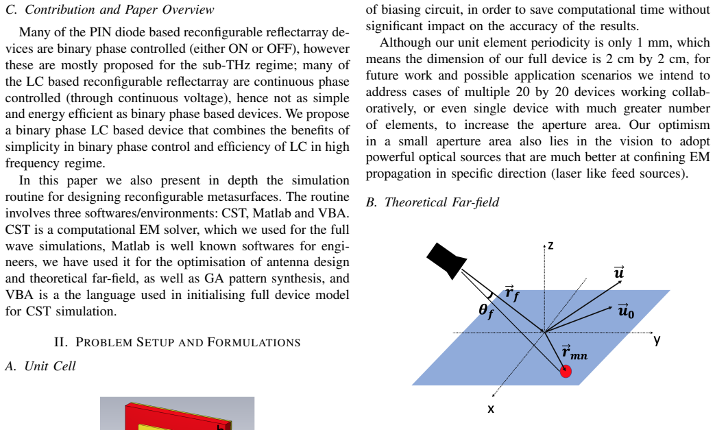
The load-bearing element is the liquid-crystal-loaded patch-antenna unit cell: a 1 mm square cell whose patch width $W = 0.714$ mm and liquid-crystal layer height $h = 0.087$ mm were tuned so that the ON and OFF states differ by nearly 180 degrees in reflection phase. The two states are modelled by assigning the liquid crystal two distinct permittivity and loss-tangent values, which shifts the unit-cell resonance. The second mechanism is the genetic algorithm, whose cost function is built from the far-field pattern's peak locations (for example, $\text{cost} = |E - E_{\text{target}}|^2$ or peak-index differences), and which searches the binary configuration space of the 400 elements. The theoretical far-field expression $E(\theta, \varphi)$ ties these together by summing the element pattern, the array factor, and the state-dependent amplitude $\Gamma_{mn}$ and phase $e^{i\varphi_{mn}}$ of each unit.
What would settle it
Measure or simulate the unit cell with the biasing network included: if the reflection phase difference between ON and OFF at 108 GHz drops well below 177 degrees, or if the reflection amplitudes in the two states move apart, the central design claim is contradicted. The same check could be done experimentally by fabricating a single cell or small array and measuring its reflection phase and amplitude under bias.
Extended reading notes
Core claim
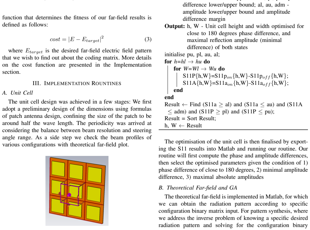
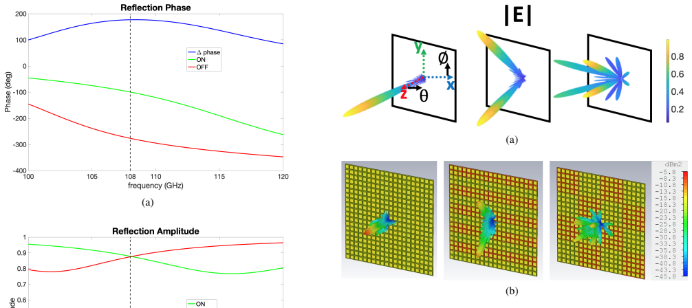
The central claim is that a 1 mm by 1 mm patch antenna on a liquid-crystal substrate can act as a binary phase-coding element at 108 GHz. Switching the liquid crystal between its low-permittivity state ($\varepsilon_\perp = 2.47$, $\tan\delta_\perp = 0.02$) and its high-permittivity state ($\varepsilon_\parallel = 3.25$, $\tan\delta_\parallel = 0.015$) changes the reflected wave's phase by 177 degrees while keeping its amplitude near 0.88 in both states, close to the 180-degree ideal for binary coding. In simulation, arranging 20 by 20 such elements and selecting each element's state with a genetic algorithm yields the expected mirror reflection when all elements are ON, anomalous reflection toward the surface normal, beam steering to a prescribed direction, and a multi-beam profile. The paper presents these as full-wave simulation results, not measurements, and notes that the aperture is only 2 cm by 2 cm, with larger apertures or tiled devices left for future work.
Load-bearing premise
The design assumes the commercial liquid crystal keeps its published permittivity and loss-tangent values at 108 GHz, and that leaving out the biasing circuit and ignoring coupling between neighbouring cells does not change the unit-cell response; if actual bias lines, temperature drift, or inter-element coupling shift the two permittivity states, the claimed 177-degree phase difference and 0.88 reflection amplitudes may not survive in a fabricated device.
Editorial extensions
If this is right
- A binary liquid-crystal reflectarray of this kind would need only low-power switching voltages, not continuous phase control, so the drive electronics could be much simpler than for existing liquid-crystal reflectarrays.
- A 20-by-20 aperture with the claimed unit cell could act as a beam-steering smart mirror for terahertz links, redirecting an incoming wave toward a user without a 100,000-element phased array.
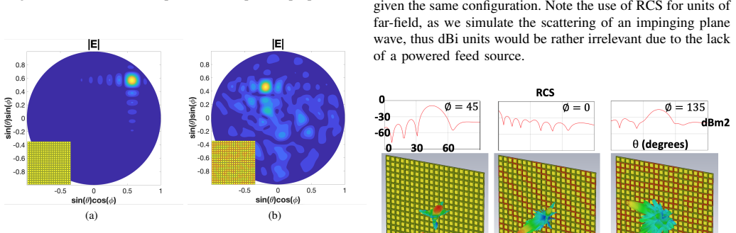
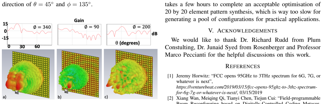
- The same 2 cm by 2 cm aperture can produce qualitatively different patterns from the same physical structure, including mirror reflection, anomalous reflection, single-beam steering, and multi-beam profiles, by changing only the ON/OFF matrix.
- The reported full-wave results suggest a path toward larger apertures by tiling multiple 20-by-20 modules, which the authors identify as future work for increasing gain and coverage.
Reading between the lines
- If the 177-degree, 0.88-amplitude unit cell is confirmed by experiment, the same binary coding idea could be extended to other terahertz functions such as polarisation conversion or radar-cross-section control, because the device already shows distinct scattering patterns from binary states.
- The omission of the biasing circuit is testable right away: adding realistic bias lines to the full-wave model would show whether the phase difference degrades, and if it does, a redesigned unit cell with integrated bias electrodes would be needed.
- The optimisation bottleneck the authors report, hours for one 20-by-20 pattern, suggests that practical real-time reconfiguration would likely need a different synthesis method, such as a fast Fourier transform based approach, rather than genetic search.
- Because the optimal ON/OFF matrices for a given beam direction are not unique, the genetic-algorithm solutions could be stored in a codebook, letting the device switch rapidly between precomputed configurations.
Signed reviews
Editorial analysis
A structured set of objections, weighed in public.
Referee Report
Summary. The manuscript reports a computational design study of a 20×20 liquid-crystal (LC) based binary-phase reflectarray metasurface for 108 GHz. The unit cell is a patch on an LC substrate modelled on Merck's GT3-23001. CST full-wave simulations are claimed to give a 177° reflection phase difference between ON and OFF states at 108 GHz with reflection amplitude 0.88 in both states. A genetic algorithm (GA) written in Matlab is used to optimize the binary ON/OFF matrix for beam-steering and multi-beam patterns, and full-device CST simulations are presented for normal incidence, oblique incidence, and a near-field feed horn. The paper also documents a cross-platform Matlab-CST-VBA implementation workflow.
Significance. If the simulated performance is reproducible, the proposed design is a useful contribution to THz communications: it is a semi-passive, binary-controlled reflectarray that avoids lossy diode phase shifters and exploits LC tuning. The paper's strengths are the full-device 20×20 CST simulation (rather than unit-cell-only extrapolation), the explicit cross-platform workflow, and the inclusion of GA code structures for pattern synthesis. However, the central quantitative claim—177° phase difference with 0.88 amplitude—is an output of a design optimization that explicitly targets ~180° phase difference, and the paper currently uses inconsistent LC permittivity values in different sections. These issues must be resolved before the reported numbers can be relied upon. The absence of experimental validation is a limitation, but not by itself disqualifying for a computational design study.
major comments (3)
- [II-A, Table 1 and III-C, Algorithm 3] The LC permittivity values are inconsistent: Table 1 lists ε⊥=2.47 and ε∥=3.25, while Algorithm 3 assigns ε=2.46 for ON and ε=3.28 for OFF. The headline 177° phase difference and 0.88 amplitude depend directly on the permittivity values used in the CST unit-cell model, so the paper must state which set of values was used in the unit-cell and full-device simulations and, if both appear, rerun the simulations with a single set and report the resulting phase and amplitude. As written, the central result cannot be traced to a definite material parameter set.
- [III-A, Algorithm 1] The reported 177° phase difference is not an independent prediction; Algorithm 1 explicitly searches for parameter pairs (h, W) satisfying a phase-difference window close to 180° (pl ≤ S11P ≤ pu) together with amplitude constraints, and the final h and W are selected by sorting these candidates. The paper should present the phase-difference and amplitude maps over the swept h and W ranges and discuss sensitivity to fabrication tolerances and to possible deviations of the LC permittivity from the datasheet values. Without this, the robustness of the 177°/0.88 claim to the design procedure itself is not established.
- [II-A] The manuscript states that the biasing circuit was omitted from the simulation 'to save computational time without significant impact on the accuracy,' but no supporting simulation or reference is provided. At 108 GHz, bias lines, alignment layers, and the LC filling structure can detune a unit cell and change both reflection phase and loss. Since the device concept relies on electronically switching the LC, this omission should either be quantified with a comparative simulation or explicitly listed as a limitation that may affect the absolute phase and amplitude numbers.
minor comments (8)
- [Section III heading] The heading 'IMPLEMENTATION ROUNTINES' should be 'IMPLEMENTATION ROUTINES'.
- [Section I-B] The phrase 'with applied electric electric field' contains a duplicated word and should be corrected.
- [Section II-A] The company name 'Merk' should be 'Merck'.
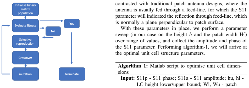
- [Section II-C and Algorithm 2] The cost function in Eq. (3) is defined as |E−E_target|², whereas Algorithm 2 defines cost as the squared difference of the peak index (|LOC−LOC_E|²). The relationship between these two definitions and the 'secondary cost conditions' mentioned in the text should be clarified.
- [Section IV-A and Fig. 6] The text says the GA beam-steering is towards θ=45°, φ=135°, but the caption of Fig. 6(b) says θ=54°, φ=135°. The two should be made consistent.
- [Section IV-B] The statement 'the area of the device is 20mm2' is incorrect for a 20×20 array of 1 mm unit cells; the area is 400 mm². Also, 'dBm2' should be 'dBsm' for radar cross section units.
- [Section I-A] The text attributes the opening of the 95 GHz to 3 THz spectrum to the FAA, while reference [1] is an FCC announcement; the agency should be corrected.
- [Section I-C] The sentence 'VBA is a the language used in initialising full device model for CST simulation' has grammatical errors and should be rewritten.
Circularity Check
No significant circularity: the 177-degree phase difference is a full-wave simulation result for an explicitly optimized unit cell, not a quantity derived from or defined by its inputs.
full rationale
The paper's central claim is a simulated design performance. Algorithm 1 sweeps h and W and selects dimensions whose S11 phase difference falls within prescribed bounds close to 180 degrees; Section IV-A then reports the achieved 177 degrees at 108 GHz. This is a design optimization outcome, not a prediction drawn from a derivation chain, so it is not circular in the sense of an input being defined in terms of the output. The LC permittivity values are taken from external literature for Merck GT3-23001, and the GA and array-factor calculations are standard numerical procedures applied to the binary state matrix; none of these steps are justified by self-citation. The inconsistency between the table values (2.47/3.25) and Algorithm 3's assigned values (2.46/3.28) is a reproducibility and correctness concern, but it does not make the derivation circular. No load-bearing self-citation or renamed known result was found.
Assumptions & free parameters
free parameters (4)
- Patch width W =
0.714 mm
- LC height h =
0.087 mm
- Unit cell periodicity =
1 mm
- Target phase difference =
180 degrees
assumptions (4)
- domain assumption LC GT3-23001 permittivity values from literature are accurate at 108 GHz
- domain assumption Omitting the biasing circuit does not significantly affect results
- domain assumption Periodic boundary condition unit-cell simulation represents the 20 by 20 array
- standard math Far-field is a product of element pattern and array factor with a cosine-power approximation
Cite this review
Pith. "Pith review of Reconfigurable Liquid Crystal Reflectarray Metasurface for THz Communications." pith.science (2026). https://pith.science/paper/2KKD3BS4
@misc{pith2026190802736,
  author       = {Pith},
  title        = {Pith review of: Reconfigurable Liquid Crystal Reflectarray Metasurface for THz Communications},
  year         = {2026},
  howpublished = {\url{https://pith.science/paper/2KKD3BS4}},
  note         = {Machine review of arXiv:1908.02736}
}
read the original abstract
We present computational studies on a proposed 20 by 20 elements electronically reconfigurable liquid crystal (LC) based binary phase reflectarray metasurface, operational at 108 GHz. LC was modelled after Mer's GT3-23001, and full wave simulations have shown a phase difference of 177 degrees between ON and OFF states, while reflection amplitudes were both 0.88 for ON and OFF. We present preliminary full wave simulation results on the Genetic Algorithm (GA) optimised far-fields. We also present the basic design procedures and cross-platform implementations on optimisation routines involving Matlab, CST and VBA environments.
Figures
Figures from the paper (4 more)

Reference graph
Works this paper leans on
-
[1]
FCC opens 95GHz to 3THz spectrum for 6G, 7G, or whatever is next
Jeremy Horwitz: “FCC opens 95GHz to 3THz spectrum for 6G, 7G, or whatever is next”, https://venturebeat.com/2019/03/15/fcc-opens-95ghz-to-3thz-spectrum- for-6g-7g-or-whatever-is-next/, 03/15/2019
work page 2019
-
[2]
Field-programmable Beam Reconfiguring based on Digitally-Controlled Coding Metasur- face
Xiang Wan, Meiqing Qi, Tianyi Chen, Tiejun Cui: “Field-programmable Beam Reconfiguring based on Digitally-Controlled Coding Metasur- face”, Scientific Reports, 2016, 6
work page 2016
-
[3]
A Pro- grammable Metasurface with Dynamic Polarization, Scattering and Focusing Control
HuanHuan Yang, Xiangyu Cao, Fan Yang, Jun Gao, Shenheng Xu, Maokun Li, Xibi Chen, Yi Zhao, Yuejun Zheng, Sijia Li: “A Pro- grammable Metasurface with Dynamic Polarization, Scattering and Focusing Control”, Scientific Reports, 2016, 6
work page 2016
-
[4]
Coding Metamaterials, Digital Metamaterials and Programmable Metamateri- als
Tiejun Cui, Meiqing Qi, Xiang Wan, Jie Zhao, Qiang Cheng: “Coding Metamaterials, Digital Metamaterials and Programmable Metamateri- als”, Light: Science and Applications , 2014, 3
work page 2014
-
[5]
Reconfigurable Tunable Microwave Devices Using Liquid Crystal
PouriaYaghmaee: “Reconfigurable Tunable Microwave Devices Using Liquid Crystal”, PhD Thesis, 2014
work page 2014
-
[6]
R. Dickie, P. Baine, R. Cahill, E. Doumanis, G. Goussetis, S. Christie, N. Mitchell, V . Fusco, D. Linton, J. Encinar, R. Dudley, D. Hindley, M. Naftaly, M. Arrebola and G. Toso: “Electrical Characterisation of Liquid Crystals at Millimetre Wavelengths Using Frequency Selective Surfaces ”, Electronic Letters, 2012, 48, no. 11
work page 2012
-
[7]
Tunable Electric-LC Resonators Using Liquid Crystal
P. Yagmaee, W. Withayachumnajul, A. K. Horestani, A. Ebrahimi: “Tunable Electric-LC Resonators Using Liquid Crystal”, IEEE, 2013, 978, pp. 382–383
work page 2013
-
[8]
Investigation on 77GHz Tunable Reflectarray Unit Cells with Liquid Crystal
A. Moessinger, R. Marin, J. Freese, S. Mueller, A. Manabe, R. Jakoby: “Investigation on 77GHz Tunable Reflectarray Unit Cells with Liquid Crystal”, Pro. EuCAP, 2006
work page 2006
Show all 13 references
-
[9]
Design and Simulation of LC Based Patch Antenna at 20 GHz Frequency
A. Karim, H. Yadav, S. Ahmad: “Design and Simulation of LC Based Patch Antenna at 20 GHz Frequency”, AIP Conference Proceedings , 2014, 1620, pp. 15-21
2014
-
[10]
Reconfigurable Liquid Crystal Reflectarray with Extended Tunable Phase Range
Saygin Bildik, Sabine Dieter, Carsten Fritzsch, Michael Frei, Christoph Fischer, Wolfgang Menzel, Rolf Jakoby: “Reconfigurable Liquid Crystal Reflectarray with Extended Tunable Phase Range”, Proceedings of the 41st European Microwave Conference , 2011, 978, pp.1292-1294
2011
-
[11]
Liquid Crystal Based Beam Scanning Reflectarrays and Their Potential in SATCOM Antennas
Perez-Palomino, G., Barba, M., Encinar, J., Cahill, R., Dickie, R., and Baine: “Liquid Crystal Based Beam Scanning Reflectarrays and Their Potential in SATCOM Antennas”, Proceedings of EuCAP 2017 , 2017
2017
-
[12]
Liquid Crystal Based Reflectarray Antenna Design
M. Y . Ismail, M. Inam: “Liquid Crystal Based Reflectarray Antenna Design”, International Scholarly and Scientific Research and Innovation, 2016, 10, 2017
2016
-
[13]
Design and Demon- stration of an Electronically Scanned Reflectarray Antenna at 100 GHz using Multi-Resonant Cells Based on Liquid Crystals
Gerardo Perez-Palomino, Mariano Barba, Jos. A. Encinar, Robert Cahill, Raymond Dickie, Paul Baine and Michael Bain: “Design and Demon- stration of an Electronically Scanned Reflectarray Antenna at 100 GHz using Multi-Resonant Cells Based on Liquid Crystals”, IEEE Transaction on...
2015
Reviewed August 14, 2026 · model on record in the stance chip above.
Discussion (0). Continue with ORCID to comment.