REVIEW 3 major objections 6 minor 6 references
Low Level RF and Timing System Design for the Cool Copper Collider
T0 review · 3 major / 6 minor · reviewed 2026-08-02 · deepseek-v4-flash
Pith's one-line read This paper claims that a single radio frequency system-on-chip (RFSoC) can directly sample and synthesize the Cool Copper Collider's 5.712 GHz accelerating RF with stability margins well above the collider's requirements, making an RFSoC-ba
desk verdict A solid engineering progress report on an RFSoC LLRF prototype with real 16.45 MW pulse-shaping data; the main caveat is that the collider-scale timing distribution is explicitly deferred, so the 'most suitable for C3' claim is ahead of the evidence. read the letter →
The pith
A machine-rendered reading of the paper's core claim, the machinery that carries it, and where it could break.
The reading
What carries the argument
The enabling device is the RFSoC, a single chip integrating ADCs, DACs, FPGA fabric, and processors. The NG-LLRF uses its internal digital mixers to sample and synthesize the C-band RF directly in higher Nyquist zones (14-bit 5 GSPS ADCs, 14-bit 10 GSPS DACs configured to 7 GSPS), with an LMK04828B PLL locking the data converters to an external RF reference. This removes analog mixer chains and makes pulse shape—including amplitude and phase reversals—purely a firmware function, with software-defined triggering and data streaming over GbE and 40 GbE.
What would settle it
Measure the pulse-to-pulse phase error of two NG-LLRF modules placed several kilometers apart and both locked to the same distributed RF reference (e.g., via the planned fiber timing interface) over 60 consecutive pulses; if the added inter-module jitter exceeds the ~150 fs total budget, the scaling claim fails. Alternatively, a single-module test with substantial beam loading (simulated by a fast load change in the cavity) that shows intra-pulse field errors beyond specification would weaken the feedback-loop portion of the claim.
Extended reading notes
Core claim
The central claim is that RFSoC data converters operating in higher-order Nyquist zones can directly sample and synthesize the C3 accelerating frequency of 5.712 GHz with stability well above the collider requirement, making the RFSoC-based NG-LLRF the most suitable LLRF solution for C3. The paper shows that in loopback the system achieves approximately 70 femtoseconds pulse-to-pulse phase fluctuation and 0.13% amplitude fluctuation, with the dominant jitter contribution coming from the solid-state amplifier, and that the same hardware can generate and measure complex high-power pulse modulations—including 8–10 ns phase flips at the amplifier and ~20 ns transitions through the klystron—while
Load-bearing premise
The paper's central claim depends on the timing and synchronization system preserving the demonstrated single-chassis phase stability when roughly 1,100 NG-LLRF modules are locked to a common RF reference across a 10-kilometer collider, but no timing distribution design or jitter budget is presented in this manuscript.
Editorial extensions
If this is right
- One NG-LLRF module replaces the conventional per-cavity analog LLRF chassis, controlling and monitoring four accelerating sections from a single RFSoC.
- Direct RF sampling eliminates analog up/down conversion stages, reducing SWaP and maintenance while enabling high channel density (~1,100 modules for all 2,200 RF stations).
- Digital pulse shaping allows fast (≈8–10 ns at SSA, ~20 ns at klystron) 180-degree phase flips suitable for SLED-type pulse compression, with observed compression ratio 2.2 on a structure not designed as a compressor.
- The demonstrated stability (≈70 fs, 0.13%) is better than the C3 requirement, and high-throughput streaming ports support AI/ML-based control at the edge.
- Estimated cost per RF channel is ~$1k, yielding a total LLRF system cost of ~$22M for the collider.
Reading between the lines
- If the same measured per-module stability holds when many modules are locked to one distributed reference—a design the paper has not yet detailed—the NG-LLRF architecture could also serve as a common platform for L-, S-, and X-band accelerators with only firmware and analog-front-end changes, as the authors suggest.
- The observed forward/reflection cross-coupling at high power implies that software-based signal separation, possibly learnable by the on-chip FPGA, will be as important as the RF front-end for accurate field control when using arbitrary pulse shapes.
- The 16.45 MW phase-flip result suggests the RFSoC drive could be used directly to modulate real SLED pulse-compressor systems, potentially simplifying high-power RF layout by removing separate driver electronics.
- A natural stress test is beam-loading compensation with several cavities driven from one module, where the single DAC's updated waveform must correct intra-pulse field droop; this is not yet demonstrated in the paper.
Signed reviews
Editorial analysis
A structured set of objections, weighed in public.
Referee Report
Summary. The paper describes the next-generation low-level RF (NG-LLRF) system for the Cool Copper Collider (C3), built around AMD/Xilinx RFSoC technology. The authors present a conceptual architecture in which roughly 1,100 NG-LLRF modules, each with 16 ADC inputs and 4 DAC outputs, would drive and monitor C3's ~4,400 RF stations. They report on a prototype chassis, its clocking and trigger hardware, and high-power tests at 16.45 MW on a C3 prototype structure, including pulse-train modulation, 180-degree phase-flip modulation, and observations of forward/reflection cross-coupling. The paper concludes that RFSoC data converters operating in higher-order Nyquist zones demonstrate stability considerably better than C3 requirements, and that the RFSoC-based platform is the most suitable LLRF solution for C3. The timing/synchronization distribution across the 10-km collider is explicitly stated to be under development.
Significance. If the claims hold, this is a valuable contribution to the LLRF design space for future linear colliders. Direct RF sampling and synthesis at 5.712 GHz without analog up/down conversion is demonstrated at MW power levels, and the high-power phase-flip measurements are directly relevant to SLED-type pulse compression. The cost estimate (~$1k per RF channel) is attractive for a 10-km machine. The paper also honestly acknowledges that the large-scale timing distribution is not yet designed. However, because the collider-level synchronization is the key link between the demonstrated single-chassis performance and the C3-wide feasibility claim, and because several quantitative statements lack error bars or clear definitions, the central conclusion is not yet fully established. These are fixable in revision rather than fatal flaws.
major comments (3)
- [Section II (System Architecture Design)] The central feasibility claim—that the RFSoC-based platform is the most suitable LLRF solution for C3—depends on distributing a common RF/trigger reference to ~1,100 modules over a 10-km linac. Section II only states 'We are working on more detailed designs of the synchronization and timing systems considering scaling up for the entire collider.' No timing-distribution topology, jitter/phase-noise budget, fiber temperature-drift analysis, or two-module phase-lock measurement is presented. The single-chassis stability numbers reported in Section I (≈70 fs, ≈150 fs with SSA) cannot be assumed to hold across the collider without this link. Please add a reference-distribution architecture and error budget, or an inter-module phase-stability measurement, before the concluding claim is made.
- [Section V (Conclusion) vs. Section II] There is a numerical inconsistency in the system-scale accounting. Section II states the C3 LLRF system requires 17,600 RF inputs and 4,400 RF outputs, consistent with 1,100 modules × 16 inputs / 4 outputs. Section V states 'at least 7,600 RF inputs and 4,400 RF outputs' with the same 1,100 modules. These numbers are mutually incompatible; 7,600 inputs is not divisible by 16 and would change the per-channel cost estimate of ~$1k. Please reconcile the totals and show the derivation from Table I explicitly.
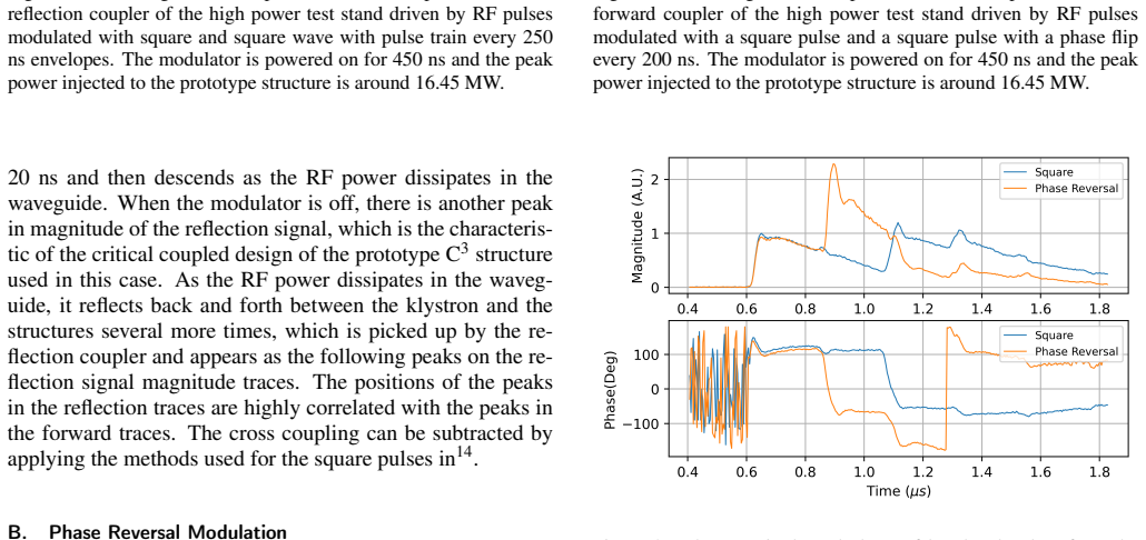
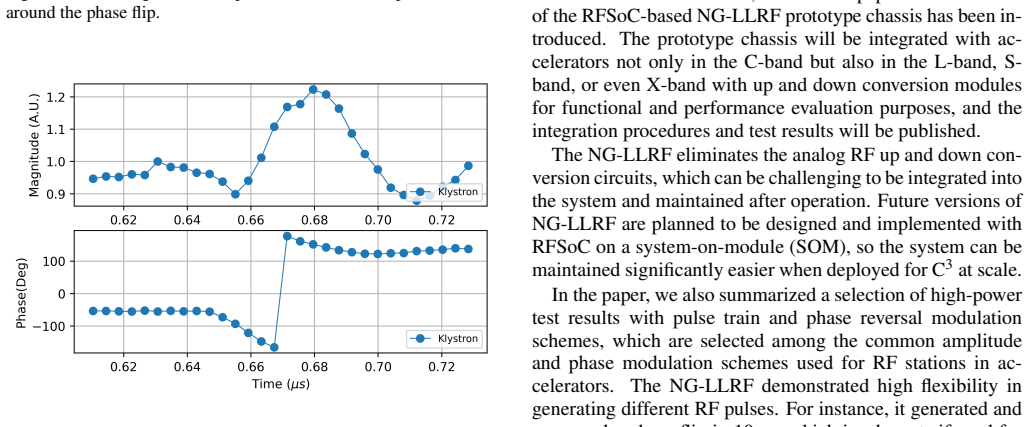
- [Section IV.B (Phase Reversal Modulation)] The key quantitative results are reported without the statistical and definitional context needed to evaluate them. The phase flip is described as 'flipped in approximately 8 ns' and 'settled in 10 ns'; the setup is said to 'demonstrate a pulse compression rate of 2.2'; and Section I quotes stability figures of 70 fs, 0.13%, 80 fs, and 150 fs. None of these are accompanied by error bars, measurement bandwidth, or the number of repetitions beyond the mention of 60 consecutive pulses for one loopback measurement. For Figure 8, the 'pulse compression rate' has no explicit definition (peak ratio? energy ratio? over what time window?). Without these details, the reader cannot verify that the performance meets C3 requirements or compare it with other LLRF platforms. Please add uncertainties, definitions, and the analysis procedure for the compression ratio.
minor comments (6)
- [Section IV (opening paragraph)] 'peal RF power at 16.45 MHz' should read 'peak RF power at 16.45 MW.'
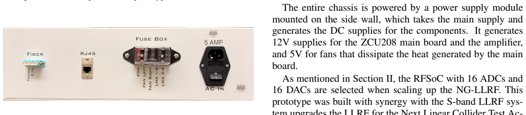
- [Section III (hardware description)] 'Gige-bit Ethernet (GbE)' should be 'Gigabit Ethernet (GbE).'
- [Table I] The table's structure is cryptic: the rows 'RF inputs 4' and 'RF outputs 1' do not obviously lead to the global totals 17,600 and 4,400. Add explanatory text or a calculation example so the reader can reproduce the module count.
- [Figures 5-8] The captions use 'baseband pulses' without defining the digital downconversion reference or the normalization used for the magnitude traces. Please define these terms at first use.
- [Section II / Abstract] The abstract speaks of '2,200 RF stations' while Section II derives 4,400 RF outputs / 1,100 modules. Clarify the relationship between stations, outputs, and modules to avoid confusion.
- [Reference 19] 'Published on AMD webiste' contains a typo; correct to 'website.'
Circularity Check
No circularity found: the paper's new high-power measurements are direct, and its reliance on prior self-cited stability work is standard cumulative experimental evidence, not a definitional or fitted-input reduction.
full rationale
The paper is an experimental design-and-test report. Its central claim—that the RFSoC-based NG-LLRF is the most suitable LLRF solution for C3—rests on two kinds of evidence: (1) previously published RFSoC stability measurements (e.g., ~70 fs phase and 0.13% amplitude in loopback, ~150 fs with SSA) cited from the authors' own prior work, and (2) new high-power measurements reported here at 16.45 MW with pulse-train and phase-flip modulations. The cited prior results are direct laboratory measurements published in peer-reviewed venues and are externally falsifiable; they are not fitted parameters nor defined in terms of the conclusion. The new measurements are similarly direct observations of the NG-LLRF driving a prototype C3 structure, and they are not predictions derived from an assumption of suitability. The paper explicitly acknowledges the undeveloped timing/synchronization distribution for the 10-km collider: 'We are working on more detailed designs of the synchronization and timing systems considering scaling up for the entire collider.' That is a stated limitation, not a circular step. No equation in the paper is shown to be equivalent to its inputs by construction, and no fitted quantity is renamed as a prediction. Therefore no significant circularity is present; the appropriate score is 0.
Assumptions & free parameters
assumptions (4)
- domain assumption Direct RF sampling at 5.712 GHz with RFSoC maintains sufficient SFDR, phase noise, and pulse-to-pulse stability for C3, as asserted from prior self-cited measurements.
- domain assumption The cross-coupling between forward and reflected couplers can be corrected by coupler matching or software algorithms so that the forward-coupler port is usable as the sole feedback signal.
- domain assumption A final RFSoC variant with 16 ADCs and 16 DACs will be available, with a 4:1 input-to-output wiring ratio, at approximately $1k per RF channel.
- domain assumption The 150 fs phase-jitter requirement is the correct C3 specification and open-loop measurements bound it for closed-loop operation.
Cite this review
Pith. "Pith review of Low Level RF and Timing System Design for the Cool Copper Collider." pith.science (2026). https://pith.science/paper/A4HJNZBD
@misc{pith2026260606630,
  author       = {Pith},
  title        = {Pith review of: Low Level RF and Timing System Design for the Cool Copper Collider},
  year         = {2026},
  howpublished = {\url{https://pith.science/paper/A4HJNZBD}},
  note         = {Machine review of arXiv:2606.06630}
}
read the original abstract
The Cool Copper Collider (C3) is a linear accelerator (LINAC) concept based on compact, high gradient, and normal conducting accelerator technology to support Higgs boson studies at 250 GeV and 550 GeV center of mass. The C3 accelerator is ten kilometers in scale and consist of 2,200 RF stations for 550 GeV center of mass. To maintain the stringent beam quality required by the collider across the LINACs, each of the cavities has a dedicated low-level RF (LLRF) system to stabilize the phase and amplitude of the field in the cavities from pulse to pulse and to compensate the fluctuation of the RF field within each pulse introduced by the beam loading process. To meet the design goals of being compact and affordable for future accelerators, we have designed the next generation LLRF (NG-LLRF) with a higher integration level based on radio frequency system-on-chip (RFSoC) technology. The NG-LLRF system samples RF signals directly and performs RF mixing digitally. The NG-LLRF has been characterized in loopback mode to evaluate the performance of the system and has also been tested with a standing-wave accelerating structure, a prototype structure for the C3 with peak RF power level up to 16.45 MW. This paper will focus on introducing the LLRF system design and timing system for C3 and the current NG-LLRF design. The high-power test results at different stages of the test setup with several pulse modulation schemes, including square pulse, pulse with phase reversals, and pulse trains, will be summarized, analyzed, and discussed.
Figures


Figures from the paper (7 more)



Reference graph
Works this paper leans on
-
[1]
1M. B. Andorf, M. Bai, P. Bhat, V . Borzenets, M. Breidenbach, S. Dasu, A. Dhar, T. d. Pree, L. Gray, S. Gessner,et al., “Esppu input: C 3 within the" linear collider vision",” arXiv preprint arXiv:2503.20829 (2025). 2C. Liu, M. E. Jones, and A. C. Taylor, “Characterizing the perfor- mance of high-speed data converters for rfsoc-based radio astronomy re- ...
arXiv 2025
-
[3]
pp. 339–355. 6C. Liu, Z. Ahmed, S. W. Henderson, R. Herbst, and L. Ruckman, “Higher order nyquist zone sampling with rfsoc data converters for astronomical and high energy physics readout systems,” arXiv preprint arXiv:2309.08640 (2023). 7C. Liu, Z. Ahmed, S. W. Henderson, R. Herbst, L. Ruckman, and T. Sat- terthwaite, “Development of rfsoc-based direct s...
arXiv 2023
-
[5]
High-power test of a c-band linear accelerating structure with an rfsoc-based llrf system,
pp. 3237–3240. 14C. Liu, L. Ruckman, R. Herbst, D. Palmer, V . Borzenets, A. Dhar, D. Ami- rari, R. Agustsson, R. Berry, and E. Nanni, “High-power test of a c-band linear accelerating structure with an rfsoc-based llrf system,” Review of Scientific Instruments96(2025). 15C. Liu, L. Ruckman, R. Herbst, B. Hong, Z. Li, K. Kim, D. Amirari, R. Agustsson, J. E...
arXiv 2025
-
[576]
X- band two-stage rf pulse compression system with correction cavity chain,
18X. Lin, H. Zha, J. Shi, Y . Jiang, F. Hu, W. Gu, Q. Gao, and H. Chen, “X- band two-stage rf pulse compression system with correction cavity chain,” Physical Review Accelerators and Beams25, 120401 (2022). 19AMD, “Rfsoc zcu208 evaluation kit,” Published on AMD webiste https://www.amd.com/en/products/adaptive-socs-and-fpgas/ evaluation-boards/zcu208.html(...
2022
-
[2022]
Evaluating direct rf sampling perfor- mance for rfsoc-based radio-frequency astronomy receivers,
pp. 1–4. 4C. Liu, L. Ruckman, and R. Herbst, “Evaluating direct rf sampling perfor- mance for rfsoc-based radio-frequency astronomy receivers,” arXiv preprint arXiv:2309.08067 (2023). 5S. W. Henderson, Z. Ahmed, J. M. D’Ewart, J. C. Frisch, R. Herbst, C. Liu, L. Ma, L. Ruckman, D. D. Van Winkle, and C. Yu, “Advanced rfsoc readout for space-based supercond...
arXiv 2023
-
[2025]
pp. 199–204. 10C. Liu, A. Dhar, M. Hoganson, E. Nanni, J. Olszewski, E. Snively, and W.-H. Tan, “High-power test and system integration of direct rf sampling based llrf control and monitoring system for s-band accelerating structures,” arXiv preprint arXiv:2604.01698 (2026). 11C. L. et al., “Direct rf sampling based llrf control system for c-band linear a...
arXiv 2026
Reviewed August 2, 2026 · model on record in the stance chip above.
Discussion (0). Continue with ORCID to comment.