REVIEW 3 major objections 4 minor 20 references
Polarization effects on high contrast imaging: measurements on THD2 Bench
T0 review · 3 major / 4 minor · reviewed 2026-08-12 · deepseek-v4-flash
Pith's one-line read A deformable mirror on the THD2 bench creates a polarization-dependent beam shift of several hundred nanometers, about ten times larger than predicted, degrading coronagraph contrast.
desk verdict A convincing weak-measurement demonstration that a deformable mirror introduces large polarization-dependent beam shifts, despite an imperfectly validated drift model. read the letter →
The pith
A machine-rendered reading of the paper's core claim, the machinery that carries it, and where it could break.
The reading
Extended reading notes
Core claim
The paper claims: "We showed that a Boston Micromachine deformable mirror located in the pupil on our bench (DM2) introduces a differential polarization shift between the PSF related to vertical and horizontal states." The measured shift is about 555 nm horizontally and 340 nm vertically for DM2 alone, which is more than ten times larger than the predicted Goos-Hänchen and Imbert-Fedorov shifts for the whole bench, and it degrades coronagraph contrast when the analyzer is rotated away from the optimized polarization state.
Load-bearing premise
The data-reduction model in Sect. 3.2 (Eq. 10: a 360-degree sinusoidal prism term plus a linear temporal drift plus a constant) fully captures all non-polarization beam motion during a measurement series. Any unmodeled systematic motion is absorbed into the fitted amplification function (Eq. 9) and would directly bias every reported shift in Table 2, including the conclusion that DM2 is the dominant contributor. The paper provides no independent validation of this drift model, and the authors explicitly call the linear drift assumption an empirical approximation.
Editorial analysis
A structured set of objections, weighed in public.
Referee Report
Summary. The paper reports polarization-dependent beam shifts on the THD2 high-contrast imaging bench. It first shows that the dark-hole contrast degrades when the analyzer is rotated away from the polarization state used for wavefront control, and reproduces the morphology with a ~800 nm tip-tilt. It then computes expected Goos-Hänchen and Imbert-Fedorov shifts for the bench mirrors using analytical expressions from Aiello et al., obtaining total shifts of order tens of nanometers. To measure such small shifts, the authors use a weak-measurement scheme with crossed polarizer/analyzer, record centroid positions versus analyzer angle, subtract a fitted 360° sinusoidal prism term and a linear temporal drift, and fit the residual with an amplification function 1/(ω−ω⊥). Table 2 reports shifts of several hundred nanometers for configurations containing DM2 (about 555 nm horizontal and 340 nm vertical for DM2 alone), far exceeding the theoretical predictions, and the paper concludes that DM2 introduces a dominant differential polarization shift.
Significance. If the quantitative result is robust, the paper is relevant to high-contrast instrument polarization error budgets: it identifies a specific pupil-plane deformable mirror as the dominant source of differential polarization shifts, and it demonstrates a bench-level impact on a FQPM coronagraph. The paper also provides a useful explicit comparison between analytical GH/IF predictions and measurements on a complete optical bench. The main strength is the use of weak measurement to amplify subpixel beam shifts; the main weakness is that the central quantitative claim depends on an empirically fitted drift model whose systematic error is not characterized.
major comments (3)
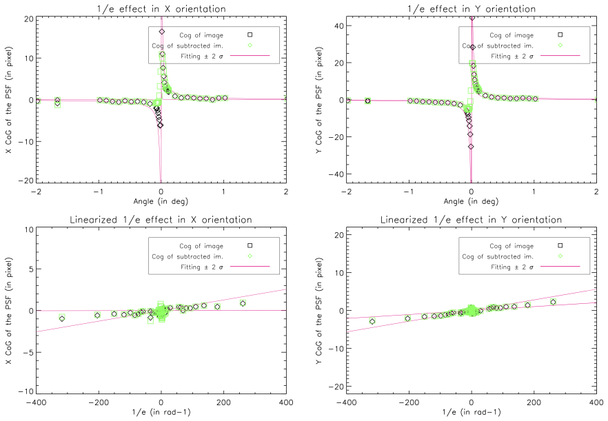
- [Section 3.2, Eq. (10)] The data-reduction model f(ω,t) = a sin(ω+φ1) + bω(t) + d1 is load-bearing for every value in Table 2, but it is not independently validated. The authors explicitly call the linear drift an empirical approximation, and the amplification fit of Eq. (9) is applied to the residuals after subtracting this model. Any unmodeled ordered motion, such as a slowly nonlinear mechanical drift or a vibration mode with an angular signature, can project onto 1/(ω−ω⊥) over the fitted interval and bias the extracted coefficient q, which is then reported as the physical shift. This is especially concerning because DM2 is the only component with a large measured shift, so a systematic at the level of tens of nanometers could change the central conclusion. The paper should show residual plots after the first fit, repeat measurements with reversed or scrambled analyzer angle order, or provide an independent drift monitor (for example, an idle analyzer position) to demonstrate that the model is adequate.
- [Section 3.2, Table 2] The reported 1σ RMS values (70 to 130 nm for the largest shifts) appear to be fit uncertainties from the inverse-function linear fit, but they do not include the uncertainty introduced by the first-stage subtraction of Eq. (10) or by the choice of fitting intervals. The fitted interval is changed by defect size (|ω−ω⊥| between 0.1° and 1° for small defects, 0.5° and 15° for large defects), yet there is no stability test of q against the interval bounds or against alternative drift models. Without this, the statistical significance of the 555 nm and 340 nm DM2 shifts is established only under the assumption that the residual noise is white, which is precisely the assumption in question.
- [Section 2.3, Table 1] The theoretical predictions in Table 1 assume that all mirrors are silver-coated, but the text notes that the DMs are aluminum-coated, and DM2 is the component later identified as the anomalous contributor. No calculation is shown for the GH/IF shifts of an aluminum-coated mirror at the DM2 incidence angle (6.55°), so the statement that the measured shifts are 'more than ten times smaller' than the predictions is not quantitatively established for the actual coating of DM2. The authors should provide predictions using the appropriate aluminum permittivity, or explicitly justify why the silver coating approximation is valid for the comparison.
minor comments (4)
- [Section 3.2, Eq. (10)] The parameter list below Eq. (10) contains a typo: it reads 'a, d1 b, d1 are parameters of the fit', which should presumably be 'a, φ1, b, d1 are parameters of the fit'.
- [Table 2] The table layout is difficult to parse: the column labels, wavelength entries, and the H/V pairs are not clearly aligned in the text, and it is not immediately clear which wavelength and optical configuration correspond to each measured value. Please reformat the table and clarify in the caption whether the quoted 1σ RMS values include any systematic component.
- [Figures 8–10] The figures would benefit from explicit axis labels and error bars on the centroid positions, and from residual plots after subtracting Eq. (10), so the reader can assess whether the drift model leaves any structure as a function of angle.
- [Section 2.2] The predicted angular shifts depend on the beam waist w0 in Eq. (2), but the value used for Table 1 is only vaguely described as the FWHM of the beam at the focal plane. Please state the numerical value of w0 and discuss how the truncated, non-Gaussian bench beam affects the predicted shifts.
Circularity Check
No significant circularity: the measured polarization shifts are extracted with an independent weak-measurement calibration and compared with theoretically computed GH/IF values that are not fitted to the data.
full rationale
The paper's central claim, that DM2 introduces a differential polarization shift, rests on direct weak-measurement data reduction (Eqs. 9 and 10) rather than on a theory-derived quantity that is fed back into the measurement. The fitted coefficient q in Eq. 9 is the reported shift in nm after centroid tracking; it is not defined in terms of the GH/IF prediction. The theoretical values in Table 1 are computed independently from external analytic expressions (Aiello et al.) and tabulated silver permittivities, with no free parameters adjusted to match the measurements. Indeed, the paper explicitly reports that the measured shifts are more than ten times larger than the predicted GH/IF values, which is the opposite of forcing theory to equal data. The only empirical modeling is the 360-degree sinusoidal plus linear-drift subtraction in Eq. 10, which the authors describe as an approximation; any inadequacy there is a systematic-error risk, not a circular step. Self-citations (Potier et al. 2020 for the dark-hole procedure, Mazoyer et al. 2014 for DM surface metrology) support standard experimental methods and do not carry the polarization-shift conclusion. No load-bearing premise reduces to its own input, and no renamed known result is presented as a new derivation.
Assumptions & free parameters
free parameters (8)
- cross-polarization angle omega_perp =
determined by transmission minimum (precision 0.01 deg)
- prism amplitude a =
fitted per series (numeric value not reported)
- prism phase phi1 =
fitted
- drift slope b =
fitted
- mean position d1 =
fitted
- amplification coefficient q =
fitted
- amplification offset d2 =
fitted
- beam waist w0 =
assumed equal to beam FWHM at focal plane
assumptions (5)
- standard math Fresnel reflection coefficients and Snell's law describe reflection at dielectric and metal interfaces.
- domain assumption The THD2 beam can be approximated as Gaussian with waist equal to the FWHM at the focal plane.
- domain assumption All reflecting surfaces can be modeled as bulk silver with tabulated permittivities, ignoring protective layers and aluminum coatings on the deformable mirrors.
- ad hoc to paper Temporal drift of the beam is linear with time during each measurement series.
- ad hoc to paper Rotation of the analyzer produces a sinusoidal beam motion with exactly 360-degree period.
Cite this review
Pith. "Pith review of Polarization effects on high contrast imaging: measurements on THD2 Bench." pith.science (2026). https://pith.science/paper/A5NXKVRT
@misc{pith2026241113746,
  author       = {Pith},
  title        = {Pith review of: Polarization effects on high contrast imaging: measurements on THD2 Bench},
  year         = {2026},
  howpublished = {\url{https://pith.science/paper/A5NXKVRT}},
  note         = {Machine review of arXiv:2411.13746}
}
abstract
The spectroscopic study of mature giant planets and low mass planets (Neptune-like, Earth-like) requires instruments capable of achieving very high contrasts ($10^{-10}-10^{-11}$) at short angular separations. To achieve such high performance on a real instrument, many limitations must be overcome: complex component defects (coronagraph, deformable mirror), optical aberrations and scattering, mechanical vibrations and drifts, polarization effects, etc. To study the overall impact on a complete system representative of high contrast instruments, we have developed a test bench at Paris Observatory, called THD2. In this paper, we focus on the polarization effects that are present on the bench which creates differential aberrations between the two linear polarization states. We compare the recorded beam positions of the two polarization states with the predicted from the Goos-H\"anchen and Imbert-Fedorov effects, both of which cause spatial shifts and angular deviations of the beam, longitudinal and transverse respectively. Although these effects have already been studied in the literature from the optical and quantum mechanical points of view, their measurement and impact on a complete optical bench are rather rare, although they are crucial for high-contrast instruments. After describing the Goos-H\"anchen and Imbert-Fedorov effects and estimating their amplitude on the THD2 bench, we present the protocol we used to measure these effects of polarization on the light beam. We compare predictions and measurements and we conclude on the most limiting elements on our bench polarization-wise.
Figures


Figures from the paper (8 more)




Reference graph
Works this paper leans on
-
[1]
Polarization Aberrations in Astronomical Tele- scopes: The Point Spread Function,
Breckinridge, J. B., Lam, W. S. T., and Chipman, R. A., “Polarization Aberrations in Astronomical Tele- scopes: The Point Spread Function,” Publications of the Astronomical Society of the Pacific 127(951), 445–468 (2015)
work page 2015
-
[2]
Polarization Effects in Reflecting Coronagraphs for White- Light Applications in Astronomy,
Breckinridge, J. B. and Oppenheimer, B. R., “Polarization Effects in Reflecting Coronagraphs for White- Light Applications in Astronomy,” The Astrophysical Journal 600(2), 1091–1098 (2004)
work page 2004
-
[3]
Threshold raw retrieved contrast in coronagraphs is limited by internal polarization,
Breckinridge, “Threshold raw retrieved contrast in coronagraphs is limited by internal polarization,” in [Final Report for NASA Grant NNX17AB29G ], (2020)
work page 2020
-
[4]
Singh, G., Galicher, R., Baudoz, P., Dupuis, O., Ortiz, M., Potier, A., Thijs, S., and Huby, E., “Active min- imization of non-common path aberrations in long-exposure imaging of exoplanetary systems,” A&A 631, A106 (Oct 2019)
work page 2019
-
[5]
Potier, A., Mazoyer, J., Wahhaj, Z., Baudoz, P., Chauvin, G., Galicher, R., and Ruane, G., “Increasing the raw contrast of VLT/SPHERE with the dark hole technique. II. On-sky wavefront correction and coherent differential imaging,” A&A 665, A136 (Sept. 2022)
work page 2022
-
[6]
Nancy Grace Roman Space Telescope coronagraph instrument overview and status,
Bailey, V. P., Bendek, E., Monacelli, B., Baker, C., Bedrosian, G., Cady, E., Douglas, E. S., Groff, T., Hildebrandt, S. R., Kasdin, N. J., Krist, J., Macintosh, B., Mennesson, B., Morrissey, P., Poberezhskiy, I., Subedi, H. B., Rhodes, J., Roberge, A., Ygouf, M., Zellem, R. T., Zhao, F., and Zimmerman, N. T., “Nancy Grace Roman Space Telescope coronagrap...
work page 2023
-
[7]
The Habitable Exoplanet Observatory (HabEx) Mission Concept Study Final Report,
Gaudi, B. S., Seager, S., Mennesson, B., Kiessling, A., and et al., “The Habitable Exoplanet Observatory (HabEx) Mission Concept Study Final Report,” arXiv e-prints , arXiv:2001.06683 (Jan. 2020)
arXiv 2001
-
[8]
Potier, A., Baudoz, P., Galicher, R., Singh, G., and Boccaletti, A., “Comparing focal plane wavefront control techniques: Numerical simulations and laboratory experiments,” A&A 635, A192 (Mar. 2020)
work page 2020
Show all 20 references
-
[9]
The Four-Quadrant Phase-Mask Coronagraph. I. Principle,
Rouan, D., Riaud, P., Boccaletti, A., Cl´ enet, Y., and Labeyrie, A., “The Four-Quadrant Phase-Mask Coronagraph. I. Principle,” PASP 112, 1479–1486 (Nov. 2000)
2000
-
[10]
Goos–h¨ anchen and imbert–fedorov shifts from a quantum- mechanical perspective,
T¨ oppel, F., Ornigotti, M., and Aiello, A., “Goos–h¨ anchen and imbert–fedorov shifts from a quantum- mechanical perspective,” New Journal of Physics 15, 113059 (nov 2013)
2013
-
[11]
B., Clemmow, P
Born, M., Wolf, E., Bhatia, A. B., Clemmow, P. C., Gabor, D., Stokes, A. R., Taylor, A. M., Wayman, P. A., and Wilcock, W. L., [ Principles of Optics: Electromagnetic Theory of Propagation, Interference and Diffraction of Light ], Cambridge University Press, 7 ed. (1999)
1999
-
[12]
Goos-H¨ anchen and Imbert-Fedorov beam shifts: An overview,
Bliokh, K. Y. and Aiello, A., “Goos-H¨ anchen and Imbert-Fedorov beam shifts: An overview,” Journal of Optics (United Kingdom) 15(1), 1–24 (2013)
2013
-
[13]
Optimized weak measure- ments of Goos-H¨ anchen and Imbert-Fedorov shifts in partial reflection,
Goswami, S., Dhara, S., Pal, M., Nandi, A., Panigrahi, P. K., and Ghosh, N., “Optimized weak measure- ments of Goos-H¨ anchen and Imbert-Fedorov shifts in partial reflection,”Optics Express 24, 6041–6051 (Mar 2014)
2014
-
[14]
SPHERE/ZIMPOL high resolution polarimetric imager. I. System overview, PSF parameters, coronagraphy, and polarimetry,
Schmid, H. M., Bazzon, A., Roelfsema, R., Mouillet, D., Milli, J., Menard, F., Gisler, D., Hunziker, S., Pragt, J., Dominik, C., Boccaletti, A., Ginski, C., Abe, L., Antoniucci, S., Avenhaus, H., Baruffolo, A., Baudoz, P., Beuzit, J. L., Carbillet, M., Chauvin, G., Claudi, R.,...
2018
-
[15]
Polarization-dependent beam shifts upon metallic reflection in high-contrast imagers and telescopes,
van Holstein, R. G., Keller, C. U., Snik, F., and Bos, S. P., “Polarization-dependent beam shifts upon metallic reflection in high-contrast imagers and telescopes,” A&A 677, A150 (Sept. 2023)
2023
-
[16]
Duality between spatial and angular shift in optical reflec- tion,
Aiello, A., Merano, M., and Woerdman, J. P., “Duality between spatial and angular shift in optical reflec- tion,” Physical Review A - Atomic, Molecular, and Optical Physics 80(6), 1–4 (2009)
2009
-
[17]
Goos-h¨ anchen and imbert-fedorov shifts: A novel perspective,
Aiello, A., “Goos-h¨ anchen and imbert-fedorov shifts: A novel perspective,” New Journal of Physics 14, 013058 (01 2012)
2012
-
[18]
Preface,
Palik, E. D., “Preface,” Handbook of Optical Constants of Solids , xvii–xviii (1997)
1997
-
[19]
Improvement of Shack–Hartmann wave-front sensor measurement for extreme adaptive optics,
Nicolle, M., Fusco, T., Rousset, G., and Michau, V., “Improvement of Shack–Hartmann wave-front sensor measurement for extreme adaptive optics,” Optics Letters 29(23), 2743 (2004)
2004
-
[20]
Deformable mirror interferometric analysis for the direct imagery of exoplanets,
Mazoyer, J., Galicher, R., Baudoz, P., Lanzoni, P., Zamkotsian, F., and Rousset, G., “Deformable mirror interferometric analysis for the direct imagery of exoplanets,” in [Adaptive Optics Systems IV], Marchetti, E., Close, L. M., and Vran, J.-P., eds., Society of Photo-Optical...
2014
Reviewed August 12, 2026 · model on record in the stance chip above.
Discussion (0). Continue with ORCID to comment.