REVIEW 3 major objections 4 minor 15 references
The camera system for the IceCube Upgrade
T0 review · 3 major / 4 minor · reviewed 2026-08-14 · deepseek-v4-flash
Pith's one-line read IceCube Upgrade cameras can map refrozen ice to within a few centimetres, simulations show.
desk verdict A solid, honest instrumentation proceedings paper: the hardware and pool tests are real, but the simulated bulk-ice precision claims lean on an untested LED-orientation assumption. read the letter →
The pith
A machine-rendered reading of the paper's core claim, the machinery that carries it, and where it could break.
The reading
What carries the argument
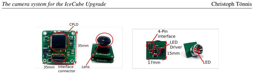
The system pairs a CMOS image sensor with a 170-degree-field-of-view lens (about 120 degrees effective in ice) and a 465 nm illumination module whose 40-degree air cone narrows to 22.5 degrees in ice. The predictive machinery is a photon-propagation Monte Carlo using the SPICE ice model, the same code used for Cherenkov light in IceCube analyses; a photon-to-pixel scaling factor derived from an air test setup converts simulated arrival directions into expected images. The bubble-column analysis measures the visible column footprint, while the bulk-ice analysis builds delta-chi-squared maps comparing simulated images against a 40-metre scattering-length, zero-tilt template.
What would settle it
Deploy the camera system in a borehole with an independently known bubble-column radius and a measured LED tilt, then compare the image-derived radius and chi-squared scattering-length estimate against those known values; a discrepancy larger than the quoted few-centimetre and 10-metre precisions would disprove the claim.
Extended reading notes
Core claim
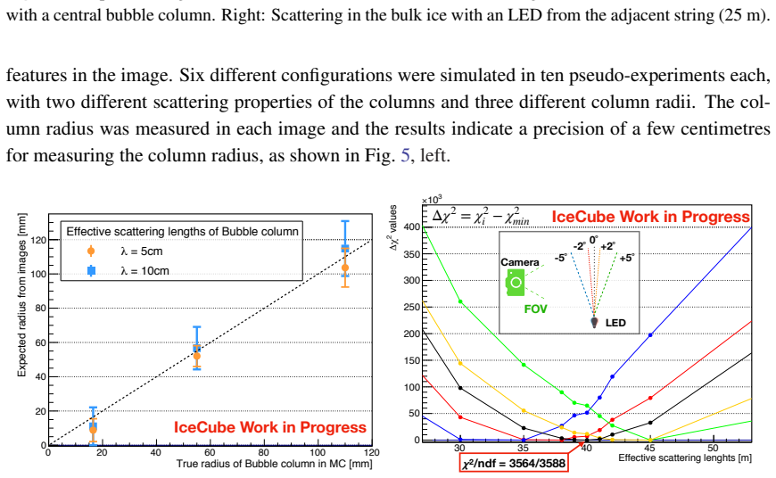
The central claim is that a camera and LED pair inside every upgraded optical module can turn IceCube's ice into an imageable calibration target. A downward-facing camera viewing an upward-pointing LED in the DOM below maps the refrozen hole ice, including the central bubble column; a sideways camera viewing an LED on an adjacent string maps scattering in the bulk ice. In Monte Carlo, the bubble-column radius is recovered to a few centimetres, and a chi-squared comparison of measured images to high-statistics templates recovers effective scattering lengths of 30 to 50 metres to about 10 metres precision, provided LED tilt is known within a few degrees. The same light-cone positions give the orientation and position of DOMs and cables, which can calibrate detector geometry in Monte Carlo simulations.
Load-bearing premise
The quoted precisions rest on a simulation chain whose photon-to-pixel calibration was measured in air and whose ice model is SPICE; if that calibration does not hold in the refrozen or bulk ice, or if the deployed LED orientation departs from the assumed few degrees, the centimetre and 10-metre numbers would not be reached.
Editorial extensions
If this is right
- If deployed as planned, every pDOM, D-Egg, and mDOM will carry three cameras, giving overlapping views of both the hole ice and the surrounding glacial ice.
- Measuring the refrozen-ice bubble column and bulk-ice scattering length in situ should reduce the dominant optical uncertainties in IceCube event reconstruction.
- Comparing images taken with LEDs pointing in different directions allows studies of anisotropy in the ice optical properties.
- Light-cone positions in the images provide DOM orientation and cable locations, feeding directly into Monte Carlo geometry calibration.
- Repeated measurements at each depth should shrink the LED-orientation uncertainty, pushing scattering-length precision toward a few metres.
Reading between the lines
- If the air-derived pixel calibration does not transfer to ice, the centimetre and 10-metre numbers would degrade; an in-ice cross-check against a known LED brightness and geometry would settle this before scientific deployment.
- The same image archive could double as a dust log for the refrozen column, since bubble and impurity distributions are visible in the reflected-light images.
- Because the illumination modules are monochromatic at 465 nm, extending the design to a second wavelength could separate scattering from absorption in the bulk-ice measurement.
- The demonstrated centimetre-level separation of two LEDs at 25 metres suggests the camera could also track slow DOM motion in the hole during the refreezing phase, not just static geometry.
Signed reviews
Editorial analysis
A structured set of objections, weighed in public.
Referee Report
Summary. The paper describes the design, prototype tests, and simulation-based performance projections of a camera system for the IceCube Upgrade. The system pairs CMOS cameras installed inside optical modules with LED illumination modules to image refrozen drill-hole ice and scattered light in the surrounding bulk ice, with the additional goal of recovering module position and orientation. After presenting engineering requirements and a quality-control workflow, the authors show swimming-pool images documenting basic functionality, then use a photon Monte Carlo with the SPICE ice model to simulate expected in-ice images. From these simulations they report O(1 cm) precision on the bubble-column radius and O(10 m) precision on the bulk-ice effective scattering length, the latter contingent on the LED orientation being known to within a few degrees.
Significance. If the headline precision claims hold, the camera system would supply a new in-situ calibration of refrozen-hole-ice and bulk-ice optical properties, directly serving the IceCube Upgrade's detector-calibration goals. The paper's strengths include a concrete prototype with characterized components, a plausible acceptance-test workflow, demonstration images from water that show basic imaging out to 25 m, and use of the standard IceCube SPICE photon-propagation model. The quoted precisions, however, come from a simulation-only self-consistency study: the photon-to-pixel scaling is calibrated in air, the expected images are generated with the same simulation chain, and the analysis recovers input parameters that were put into the simulation. That is legitimate as design validation, but it is not an end-to-end validation of the measurement, and the central scattering-length claim rests on an orientation-assumption that the paper does not demonstrate is identifiable.
major comments (3)
- [Section 4, Fig. 5 (right)] The claimed O(10 m) precision for the bulk-ice scattering length is shown only for five discrete LED-tilt values, with the per-tilt chi-square minimum subtracted. This demonstrates sensitivity to the scattering length when the tilt is fixed, but it does not establish that the scattering length and LED orientation can be separately determined in a joint fit. Since the same camera system is intended to determine DOM orientation from the light-cone images, and Table 1 only specifies camera alignment within 5 degrees, the assumption that the LED orientation is 'known within a few degrees' is load-bearing and unsupported. A continuous two-parameter fit, or an explicit demonstration that the orientation can be recovered from the same simulated images without degrading the scattering-length sensitivity, is needed before the precision claim is credible. The statement that multiple depth measurements will reduce the orientation uncertainty is an assertion that is not backed by a combined-fit simulation.
- [Section 4, photon-to-pixel calibration] The precision of the delta-chi-squared analysis depends on absolute image intensities, yet the photon-to-pixel scaling factor is derived from a test setup in air, with no uncertainty quoted for the factor and no validation that the calibration transfers to ice. The in-ice environment differs in glass refraction, scattering, and the angular response of the illumination module, so the transferability of an air-derived absolute calibration is not self-evident. The authors should either provide a systematic uncertainty for the scaling factor, validate it with an in-ice or water measurement, or explicitly restrict the precision claims to the idealized simulation model.
- [Section 4, Fig. 5 (left)] The bubble-column-radius precision is reported as 'a few centimetres', but the measurement procedure is described only as 'measuring size of the visible features in the image', and the figure does not show fit lines, per-configuration scatter, or systematic error estimates. With six configurations and ten pseudo-experiments each, the claimed O(1 cm) precision is not yet robustly demonstrated against the main identified systematics, in particular the photon-to-pixel calibration and the choice of effective scattering length in the column. The authors should define the radius estimator, report the measured versus true radius for each configuration, and state which uncertainties enter the quoted precision.
minor comments (4)
- [Section 4, Fig. 5 (right)] The red box mentioned in the text is not clearly marked in the figure, and the axis label appears garbled as 'values χ2Δ' with '3 10×'; the axes should be labeled as 'Δχ2' with correct scientific notation.
- [Section 2] The paper uses 'LED orientation', 'camera alignment', and 'relative orientations of light' without a consistent definition of the relevant angles; defining the reference frame and the tilt convention in a short paragraph or diagram would substantially improve reproducibility.
- [Section 3] The swimming-pool images demonstrate the basic functionality well, but the text says the captured intensity 'varied with distance' without quantitative comparison to expectation; one sentence with the measured-versus-expected trend would make this subsection more informative.
- [Section 1] The sentence 'The camera system is to be installed in all three types of DOMs' is clear, but the subsequent description of camera count per DOM is easy to misread; a small table summarizing the number and pointing direction of cameras and illumination modules per DOM type would help the reader.
Circularity Check
No significant circularity: the camera-precision claims are a calibrated Monte Carlo closure test, not a derivation that re-enters its own inputs.
full rationale
The paper's central performance claims (O(1 cm) bubble-column radius, O(10 m) scattering length) are statements about a simulated analysis chain. The chain is: lab measurements fix a photon-to-pixel scaling factor ('This factor is derived by comparing measurement in a test setup in air...'), the SPICE ice model and photon-propagation code generate expected images, and the analysis recovers known input parameters from those simulated images. This is a self-consistency exercise in the sense that the 'data' and the template share the same simulation; however, it is not circular by the standards of the review. The numerical precisions are nontrivial outputs of photon statistics, geometry, and the Δχ2 comparison; they are not equal by construction to the input scattering lengths or radii. The paper does not fit the scattering length to the same data and then call the fit a prediction. The LED-orientation caveat ('under the assumption that the LED orientation is known within a few degrees') is an explicitly stated condition, not an imported result; whether that condition can be met in a joint fit is a correctness/robustness concern, not a circularity. The simulation tools are cited to the standard IceCube SPICE model and propagation code, which are external to this paper's derivation, and no uniqueness theorem or ansatz is smuggled in through self-citation. The swimming-pool and air tests provide independent hardware demonstrations, although they do not validate the in-ice precision. Overall, no load-bearing step reduces to its own inputs by definition.
Assumptions & free parameters
free parameters (3)
- photon-to-pixel intensity scaling factor =
not stated
- template effective scattering length =
40 m
- bubble column effective scattering length =
5 cm and 10 cm
assumptions (5)
- domain assumption The SPICE ice model accurately describes photon scattering and absorption in South Pole glacial ice at the wavelengths and length scales used.
- domain assumption The photon propagation Monte Carlo code [14], originally used for Cherenkov light, is applicable to LED light at 465 nm with the same ice model.
- domain assumption The intensity scaling factor measured in a single air test is representative of the camera behavior inside a DOM in water and ice, including glass refraction and housing effects.
- domain assumption LED orientation relative to the camera is known within a few degrees.
- domain assumption The bubble column can be modeled as a homogeneous cylindrical scatterer with a single effective scattering length.
Cite this review
Pith. "Pith review of The camera system for the IceCube Upgrade." pith.science (2026). https://pith.science/paper/BO5EWFV2
@misc{pith2026190807734,
  author       = {Pith},
  title        = {Pith review of: The camera system for the IceCube Upgrade},
  year         = {2026},
  howpublished = {\url{https://pith.science/paper/BO5EWFV2}},
  note         = {Machine review of arXiv:1908.07734}
}
read the original abstract
The IceCube Neutrino Observatory is a cubic kilometer volume neutrino detector installed in the Antarctic at the geographic South Pole. Neutrinos are detected through the observation of Cherenkov light from charged relativistic particles generated in neutrino interactions, using an array of 86~strings of optical sensor modules. Currently an upgrade to the IceCube detector is in preparation. This IceCube Upgrade will add seven additional strings with new optical sensors and calibration devices. A new camera system is designed for this upgrade to be installed with the new optical modules. This camera system will study bulk ice properties and the refrozen ice in the drill hole. The system can also be utilized to provide information on the detector geometry including location and orientation of the optical modules and cables that can be used to calibrate IceCube Monte Carlo simulations. A better understanding of the refrozen ice in the drill hole including the complementary knowledge of the optical properties of the surrounding glacial ice will be obtained by surveying and analyzing the images from this system. The camera system consists of two types of components: an image sensor module and an illumination module. The image sensor module uses a CMOS image sensor to take pictures for the purpose of calibration studies. The illumination module emits static, monochromatic light into a given direction with a specific beam width and brightness during the image taking process. To evaluate the system design and demonstrate its functionality, a simulation study based on lab measurements is performed in parallel with the hardware development. This study allows for the development of the preliminary image analysis tool for the system. We present the prototype of the camera system and the results of the first system demonstrations.
Figures


Figures from the paper (2 more)

Reference graph
Works this paper leans on
-
[1]
IceCube Collaboration, M. G. Aartsen et al., JINST 12 (2017) P03012
2017
-
[2]
IceCube Collaboration, M. G. Aartsen et al., Nucl. Instrum. Meth. A, 711 (2013) 73-89
work page 2013
-
[3]
IceCube Collaboration, R. Abbasi et al., Nucl. Instrum. Meth. A, 700 (2013) 188-220
work page 2013
-
[4]
IceCube Collaboration, M. G. Aartsen et al., Science 342 (2013) 1242856
2013
-
[5]
IceCube Collaboration, M. G. Aartsen et al., Science 361 (2018) 147-151
2018
-
[6]
IceCube Collaboration, M. G. Aartsen et al., Phys. Rev. Lett. 120 (2018) no.7, 071801
work page 2018
-
[7]
IceCube Collaboration, M. G. Aartsen et al., Adv. Space Res. 62 (2018) 2902
work page 2018
-
[8]
IceCube Collaboration, M. G. Aartsen et al., Eur . Phys. J.C 78 (2018) no.10 831
work page 2018
Show all 15 references
-
[9]
IceCube Collaboration, M. G. Aartsen et al., Eur . Phys. J.C 76 (2016) no.3 133
2016
-
[10]
IceCube Collaboration, PoS(ICRC2019)1031 (these proceedings)
-
[11]
IceCube-Gen2 Collaboration, PoS(ICRC2017)1040 (2018)
2018
-
[12]
P. O. Hulth for the IceCube Collaboration in VLVnT13, 325, 2013
2013
-
[13]
Chirkin for the IceCube Collaboration in ICRC2013, p
D. Chirkin for the IceCube Collaboration in ICRC2013, p. 580, 2013
2013
-
[14]
Chirkin for the IceCube Collaboration, Nucl
D. Chirkin for the IceCube Collaboration, Nucl. Instrum. Meth. A, 725 (2013) 141-143
2013
-
[15]
IceCube Collaboration, PoS(ICRC2019)926 (these proceedings). 8
Reviewed August 14, 2026 · model on record in the stance chip above.
Discussion (0). Continue with ORCID to comment.