REVIEW 4 major objections 4 minor 22 references
The Space Coronagraph Optical Bench (SCoOB): X. Dark zone maintenance
T0 review · 4 major / 4 minor · reviewed 2026-08-15 · deepseek-v4-flash
Pith's one-line read The paper claims that dark zone maintenance can hold a vortex coronagraph's dark hole contrast near its post-digging level while wavefronts drift, with simulations of two algorithms and bench tests of one.
desk verdict A modest, honest testbed paper: known DZM algorithms applied to a vortex coronagraph, with a useful negative finding about LDFC and low-order aberrations, but the quantitative contrast-maintenance claim rests on noiseless simulations. read the letter →
The pith
A machine-rendered reading of the paper's core claim, the machinery that carries it, and where it could break.
The reading
What carries the argument
The central mechanism is the asymmetric response of the focal plane: in the bright field, intensity changes linearly with wavefront perturbations, while inside the dark hole the response is quadratic. LDFC exploits the linearity with a two-stage calibration that builds a control matrix from Hadamard probe patterns decomposed into DM eigenmodes, requiring one image per loop and no extra DM probes. The EKF alternative maintains an estimate of the complex electric field at each dark-hole pixel from single images, using a small DM dither for phase diversity, and converts the field estimate into DM commands through the EFC Jacobian. The vector vortex coronagraph, a focal-plane mask that suppresses on-axis starlight, is the optical element whose properties make LDFC's bright-field response weak for low-order modes.
What would settle it
On the SCoOB bench, inject a slowly growing low-order Zernike mode into the deformable mirror while LDFC is closed-loop and record the dark hole contrast: if contrast returns to the post-iEFC floor, the claim that LDFC is insensitive to such modes with a vortex coronagraph is refuted; if contrast degrades while simulation predicts it should hold, the Fresnel model is the part to doubt.
Extended reading notes
Core claim
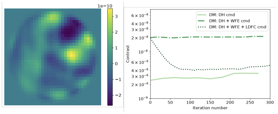
On its own terms, the paper's central claim is that dark zone maintenance can be decoupled from dark hole digging: once implicit electric field conjugation (iEFC) has dug the hole, LDFC and EKF-based DZM can each keep the monochromatic contrast at the final iEFC level while the wavefront drifts, using one image per iteration and no probing of the dark hole. The simulation evidence covers single DM eigenmodes, random walks of DM actuators, and slowly accumulating low-order Zernike errors. The testbed evidence is for LDFC only: it restores the iEFC floor after injected DM eigenmode errors, but the bench's ambient low-order drift leaks through because LDFC with a vortex coronagraph is insensitive to low-order modes. The paper identifies that limitation explicitly and names low-order wavefront sensing as the complementary correction.
Load-bearing premise
The load-bearing premise is that the Fresnel model of the bench, including its measured surface errors, predicts real optical behavior closely enough that simulation conclusions about LDFC and EKF transfer to the testbed.
Editorial extensions
If this is right
- A coronagraph could observe a target for hours while DZM keeps the dark hole at its dug-in contrast, eliminating the need to alternate to a reference star.
- LDFC adds no perturbation to the dark hole during maintenance, so it can run while science data are being taken.
- The simulated insensitivity of LDFC to low-order modes means a practical LDFC system for a vortex coronagraph should include a low-order wavefront sensor.
- EKF-based DZM can stabilize contrast against slowly accumulating low-order Zernike drift and random-walk DM drift, covering regimes LDFC misses.
- The convergence behavior of EKF, with a brief contrast dip in early iterations, means operational loops should zero the controller gain for the first iterations.
Reading between the lines
- A direct continuation is to run the EKF algorithm on the bench under the same injected eigenmode tests; success would cover the low-order drift that LDFC misses.
- Marrying LDFC with low-order wavefront sensing on the same bench should close the gap, since the two sensors respond to complementary mode ranges.
- For mission design, the DZM choice may reduce to a trade-off: LDFC is model-free and simple but blind to low-order modes, while EKF needs a state-space model and covariance tuning but handles those modes in simulation.
- The single-image-per-iteration property suggests DZM could be interleaved with science frames rather than occupying dedicated calibration time, an operational pattern the paper does not develop.
Signed reviews
Editorial analysis
A structured set of objections, weighed in public.
Referee Report
Summary. This manuscript (SCoOB X) reports simulations and preliminary testbed demonstrations of two dark-zone maintenance (DZM) algorithms for the SCoOB vortex coronagraph: model-free linear dark field control (LDFC) and an extended Kalman filter (EKF) estimator/controller. In POPPY simulations, both algorithms are claimed to recover and hold dark-hole contrast near the final iEFC contrast level under static and dynamic wavefront errors, including a single DM eigenmode, random-walk actuator drift, and accumulating low-order Zernike modes. On the testbed, LDFC is shown to correct an injected DM eigenmode and a sum of low-order DM eigenmodes, while it fails to correct the bench's own low-order drift. The paper honestly states that detector noise is omitted from simulations and that the testbed LDFC results are preliminary.
Significance. The work addresses an important operational problem for space coronagraphs: maintaining high contrast during long exposures without re-digging a dark hole. Its strengths include explicit step-by-step algorithm descriptions with matrix dimensions, a public code reference, and an honest report of LDFC's failure on low-order drift, which is a useful falsifiable observation. The comparison of LDFC and EKF on the same simulated SCoOB model is also valuable. However, the quantitative headline claim—that both algorithms maintain contrast at the final iEFC level—is supported only by noiseless simulations, so the significance of that specific quantitative statement is currently limited until realistic noise is included or the claim is deliberately softened.
major comments (4)
- [Section 3, first paragraph] The sentence 'We have not considered detector noise for these simulations' is a load-bearing limitation. The quantitative claim in Sections 3.1 and 3.2 that LDFC and EKF maintain contrast at the level of the final iEFC contrast is established only in a noiseless idealization. For EKF, the measurement is the dark-hole intensity and the residual field is deliberately driven to a small value, so without simulated photon and read noise the filter can exploit intensity changes far below what a real camera can detect. For LDFC, the signal is a small intensity change in the bright field, and photon noise on that bright background sets a detection floor. Please either include noise-inclusive simulations with stated Q, R, and dither values, or explicitly soften the quantitative claims to 'noiseless-simulation performance' in the abstract, Section 3, and conclusions.
- [Section 4, Figures 8 and 9] The testbed LDFC demonstration is preliminary: the plotted curves have no error bars, the runs are single realizations, and the bench's own low-order drift remains uncorrected. The text states that the contrast curves with only the DH command and with the WFE added were recorded only every 30 and 15 iterations, respectively, so the baselines are sparsely sampled. This is acceptable for a qualitative demonstration, but it cannot substitute for the noise-inclusive simulation needed to support the quantitative maintenance claim or to establish repeatability.
- [Section 3.2, EKF equations] The EKF results depend on quantities that are not reported: the process noise Q, the measurement noise R, the dither amplitude, and the control gain schedule. The text mentions that the gain is set to zero for the first 10-20 iterations but does not state the subsequent gain or any parameter values. Without these, the reader cannot judge whether the demonstrated maintenance is robust to reasonable parameter choices or is specific to the simulated WFE cases. Please state the values used and, ideally, include a short sensitivity study over Q, R, and dither amplitude.
- [Section 3 and Section 4, model validation] The simulation conclusions are extrapolated to the bench through the POPPY Fresnel model that 'accounts for the surface error measurements.' The only direct model-testbed comparison is qualitative (Figures 1 versus 7). Given that the testbed shows a low-order drift that LDFC cannot correct and the simulations already predict insensitivity to low-order Zernikes, the transfer of the EKF simulation results to the real SCoOB bench remains unvalidated. Please add a quantitative model-versus-testbed comparison of the LDFC response curves or state a clear validation plan for EKF, or alternatively limit the conclusions to the simulation model.
minor comments (4)
- [Section 4] The phrase 'scoob stategithub respository' appears to be a malformed reference; please provide a proper URL or a complete citation for the repository.
- [Section 2.2, Step 1] The sentence 'we assume that the electric field has not drifted and that the state/open loop electric field is the field at the end of DH digging' is unclear; please define the state vector explicitly, stating that it contains the real and imaginary parts of the field at each dark-hole pixel, and clarify the relationship between the state and the open-loop field.
- [Equation (4)] In Equation (4), the notation N(0, sigma_drift^2 I) is consistent with a multivariate normal distribution, but the text describes sigma_drift as 'the standard deviation' of the normal distribution; please state explicitly that sigma_drift is the per-actuator standard deviation and that the increments are independent across actuators.
- [Figures 2 through 6] The dashed, dotted, and solid curves are described in the captions but are not labeled inside the panels; adding a legend or explicit curve labels would make the figures substantially easier to read.
Circularity Check
LDFC tests inject the same DM eigenmodes used to build the control matrix, so the positive correction result is forced by calibration; EKF and testbed results provide independent content.
-
fitted input called prediction
[Section 2.1 (Steps 5-8), Section 3.1 (Fig. 2), Section 4 (Fig. 8)]
"Step 5: Derive the second basis set, called the 'DM eigenmodes' (V* HAD) by doing a singular value decomposition (SVD) of the transpose of the filtered IF cube ... Step 6: Repeat Step 3 but with the DM eigenmodes as the new basis ... Step 8: Find the LDFC control matrix (CtrlMat) by inverting the filtered IF cube,EIG,filt. ... We first tested the algorithm by introducing a static WFE made of a single DM eigenmode."
The LDFC control matrix is constructed by inverting the measured bright-field response to the DM eigenmodes (IF cube,EIG,filt). The test disturbance is then deliberately chosen as a single DM eigenmode from that same basis, and the random-walk test is a superposition of the spanning eigenmode set. Under the linear bright-field model of Eq. (3), any controller formed by inverting its own calibration response will null those exact modes, so the recovered iEFC contrast is a closed-loop consistency check of the calibration rather than an independent prediction. The testbed injection of a single eigenmode (Fig. 8) has the same structure. This does not undermine the independent negative result that LDFC cannot correct the testbed's low-order drift.
full rationale
The paper is largely self-contained: LDFC and EKF are implemented from published control laws, and the POPPY Fresnel model is an external input described in a companion paper, not fitted to the DZM outcomes. No load-bearing self-citation chain is present; the .toml model is used as a forward model rather than as a uniqueness argument. However, the positive LDFC demonstration is partially circular: the controller is calibrated on DM eigenmodes and then tested by injecting those same eigenmodes, so the correction is guaranteed by construction in the linear regime. The EKF simulations are model-matched and noiseless, as the paper states: 'We have not considered detector noise for these simulations and it will be accounted for in future work.' This makes the quantitative claim that EKF maintains contrast at the final iEFC level a simulation self-consistency result rather than an empirical validation; it is a stated limitation rather than a hidden fit. The testbed LDFC result is genuine hardware evidence, but its injected-WFE cases again use the calibration eigenmode basis. Overall, partial circularity appears in the LDFC demonstration, while the EKF implementation and the testbed drift limitation retain independent content.
Assumptions & free parameters
free parameters (4)
- sigma_drift =
0.1 nm
- EKF process noise Q =
not specified
- EKF measurement noise R =
not specified
- LDFC bright field mask threshold =
not specified
assumptions (4)
- domain assumption The state transition matrix F is identity; wavefront drift is modeled as a random walk with no dynamics.
- domain assumption The initial electric field is assumed undrifted at the start of EKF.
- domain assumption The LDFC linearization neglects |E_DM|^2 in the bright field.
- domain assumption POPPY Fresnel model of SCoOB with measured surface errors faithfully represents the testbed.
Cite this review
Pith. "Pith review of The Space Coronagraph Optical Bench (SCoOB): X. Dark zone maintenance." pith.science (2026). https://pith.science/paper/GRM3QTQH
@misc{pith2026260802962,
  author       = {Pith},
  title        = {Pith review of: The Space Coronagraph Optical Bench (SCoOB): X. Dark zone maintenance},
  year         = {2026},
  howpublished = {\url{https://pith.science/paper/GRM3QTQH}},
  note         = {Machine review of arXiv:2608.02962}
}
abstract
The Space Coronagraph Optical Bench (SCoOB) is a vacuum high contrast imaging testbed designed to demonstrate starlight suppression at optical wavelengths and obtain contrasts better than 10$^{-8}$ in a one-sided dark hole from 3 to 10 $\lambda/D$ using a vector vortex coronagraph (VVC) mask. Some of the recent efforts have been in testing dark zone maintenance (DZM) algorithms which are used to stabilize the contrast in the presence of wavefront drifts and allow for the long integration times required by exoplanet observations. In this work, we discuss the results from simulations with two DZM algorithms - linear dark field control (LDFC) and extended Kalman Filter-based (EKF) DZM. We also report preliminary results from the testbed with LDFC.
Figures


Figures from the paper (7 more)



Reference graph
Works this paper leans on
-
[1]
A laboratory demonstration of the capability to image an earth-like extrasolar planet,
Trauger, J. T. and Traub, W. A., “A laboratory demonstration of the capability to image an earth-like extrasolar planet,”Nature446, 771–773 (Apr. 2007)
work page 2007
-
[2]
The Nancy Grace Roman Space Telescope Coronagraph Instrument (CGI) technology demonstration,
Kasdin, N. J., Bailey, V. P., Mennesson, B., Zellem, R. T., Ygouf, M., Rhodes, J., Luchik, T., Zhao, F., Riggs, A. J. E., Seo, B.-J., Krist, J., Kern, B., Tang, H., Nemati, B., Groff, T. D., Zimmerman, N., Mac- intosh, B., Turnbull, M., Debes, J., Douglas, E. S., and Lupu, R. E., “The Nancy Grace Roman Space Telescope Coronagraph Instrument (CGI) technolo...
work page 2020
-
[3]
Design of the vacuum high contrast imaging testbed for CDEEP, the Coronagraphic Debris and Exoplanet Exploring Pioneer,
Maier, E. R., Douglas, E. S., Kim, D. W., Su, K., Ashcraft, J. N., Breckinridge, J. B., Choi, H., Choquet, E., Connors, T. E., Durney, O., Gonzales, K. L., Guthery, C. E., Haughwout, C. A., Heath, J. C., Hyatt, J., Lumbres, J., Males, J. R., Matthews, E. C., Milani, K., Montoya, O. M., N’Diaye, M., Noenickx, J., Pogorelyuk, L., Ruane, G., Schneider, G., S...
2020
-
[4]
Ashcraft, J. N., Choi, H., Douglas, E. S., Derby, K., Gorkom, K. V., Kim, D., Anche, R., Carter, A., Durney, O., Haffert, S., Harrison, L., Kautz, M., Lumbres, J., Males, J. R., Milani, K., Montoya, O. M., and Smith, G. A., “The space coronagraph optical bench (SCoOB): 1. Design and assembly of a vacuum- compatible coronagraph testbed for spaceborne high-...
work page 2022
-
[5]
The space coronagraph optical bench (SCoOB): 4. vacuum performance of a high contrast imaging testbed,
Van Gorkom, K., Douglas, E. S., Milani, K., Ashcraft, J. N., Anche, R. M., Jenkins, E., Ingraham, P., Haffert, S., Kim, D., Choi, H., and Durney, O., “The space coronagraph optical bench (SCoOB): 4. vacuum performance of a high contrast imaging testbed,” in [Space Telescopes and Instrumentation 2024: Optical, Infrared, and Millimeter Wave],13092, 680, SPIE
2024
-
[6]
Implicit electric field conjugation: Data-driven focal plane control,
Haffert, S. Y., Males, J. R., Ahn, K., Van Gorkom, K., Guyon, O., Close, L. M., Long, J. D., Hedglen, A. D., Schatz, L., Kautz, M., Lumbres, J., Rodack, A., Knight, J. M., and Miller, K., “Implicit electric field conjugation: Data-driven focal plane control,”673, A28
-
[7]
The space coronagraph optical bench (SCoOB): 8. end-to-end numerical modeling of the testbed to estimate the contrast limits,
Anche, R. M., Van Gorkom, K., Milani, K., Derby, K., Jenkins, E., Ashcraft, J., Subramanian, S. K., Ingraham, P., Kim, D., Choi, H., Durney, O., and Douglas, E., “The space coronagraph optical bench (SCoOB): 8. end-to-end numerical modeling of the testbed to estimate the contrast limits,” in [Techniques and Instrumentation for Detection of Exoplanets XII]...
-
[8]
The space coronagraph optical bench (scoob): 5. end-to-end simulation of polarization aberrations,
Anche, R. M., Van Gorkom, K. J., Ashcraft, J. N., Douglas, E., Jenkins, E. L., Haffert, S. Y., and Millar- Blanchaer, M. A., “The space coronagraph optical bench (scoob): 5. end-to-end simulation of polarization aberrations,” in [Space Telescopes and Instrumentation 2024: Optical, Infrared, and Millimeter Wave], 13092, 2203–2213, SPIE (2024)
2024
Show all 22 references
-
[9]
The space coronagraph optical bench (scoob): 3. mueller matrix polarimetry of a coronagraphic exit pupil,
Ashcraft, J. N., Douglas, E. S., Anche, R. M., Van Gorkom, K., Jenkins, E., Melby, W., and Millar- Blanchaer, M. A., “The space coronagraph optical bench (scoob): 3. mueller matrix polarimetry of a coronagraphic exit pupil,” in [Space Telescopes and Instrumentation 2024: Optic...
2024
-
[10]
The space coronagraph optical bench (scoob): 6. demonstration of lyot low order wavefront control combined with high order wavefront control using a vortex coronagraph,
Milani, K., Van Gorkom, K., Mendillo, C. B., Anche, R., Ashcraft, J. N., Derby, K., Males, J. R., Schilper- oort, A., and Douglas, E. S., “The space coronagraph optical bench (scoob): 6. demonstration of lyot low order wavefront control combined with high order wavefront contr...
2025
-
[11]
The space coronagraph optical bench (scoob): 7. design, fabrication, and first light for a self-coherent camera,
Derby, K., Milani, K., Hathaway, G. C., Liberman, J., Van Gorkom, K., Anche, R., Schilperoort, A., Fucetola, C., Chalifoux, B., Hewawasam, K., et al., “The space coronagraph optical bench (scoob): 7. design, fabrication, and first light for a self-coherent camera,” in [Techniq...
2025
-
[12]
Demonstra- tions of adjoint electric field conjugation for a vortex coronagraph,
Milani, K., Will, S. D., Van Gorkom, K., Douglas, E. S., Ashcraft, J. N., and Cahoy, K., “Demonstra- tions of adjoint electric field conjugation for a vortex coronagraph,”Journal of Astronomical Telescopes, Instruments, and Systems11, 039001 (July 2025)
2025
-
[13]
The space coronagraph optical bench (scoob): 11. modeling and correction of chromatic aberrations,
Van Gorkom, K. et al., “The space coronagraph optical bench (scoob): 11. modeling and correction of chromatic aberrations,”14145, SPIE
-
[14]
Spatial linear dark field control: stabilizing deep contrast for exoplanet imaging using bright speckles,
Miller, K., Guyon, O., and Males, J., “Spatial linear dark field control: stabilizing deep contrast for exoplanet imaging using bright speckles,”Journal of Astronomical Telescopes, Instruments, and Systems3, 049002 (Oct. 2017)
2017
-
[15]
Spatial linear dark field control on Subaru/SCExAO. Maintaining high contrast with a vAPP coronagraph,
Miller, K. L., Bos, S. P., Lozi, J., Guyon, O., Doelman, D. S., Vievard, S., Sahoo, A., Deo, V., Jovanovic, N., Martinache, F., Snik, F., and Currie, T., “Spatial linear dark field control on Subaru/SCExAO. Maintaining high contrast with a vAPP coronagraph,”A&A646, A145 (Feb. 2021)
2021
-
[16]
First on-sky demonstration of spatial Linear Dark Field Control with the vector-Apodizing Phase Plate at Subaru/SCExAO,
Bos, S. P., Miller, K. L., Lozi, J., Guyon, O., Doelman, D. S., Vievard, S., Sahoo, A., Deo, V., Jovanovic, N., Martinache, F., Currie, T., and Snik, F., “First on-sky demonstration of spatial Linear Dark Field Control with the vector-Apodizing Phase Plate at Subaru/SCExAO,”A&...
2021
-
[17]
Experimental demonstration of spectral linear dark field control at NASA’s high contrast imaging testbeds,
Poon, P. K., Potier, A., Ruane, G., Walter, A. B., Eldorado Riggs, A. J., Noyes, M., Mejia Prada, C., Ahn, K., and Guyon, O., “Experimental demonstration of spectral linear dark field control at NASA’s high contrast imaging testbeds,”arXiv e-prints, arXiv:2309.17449 (Sept. 2023)
2023 arXiv
-
[18]
Dark Hole Maintenance and A Posteriori Intensity Estimation in the Presence of Speckle Drift in a High-contrast Space Coronagraph,
Pogorelyuk, L. and Kasdin, N. J., “Dark Hole Maintenance and A Posteriori Intensity Estimation in the Presence of Speckle Drift in a High-contrast Space Coronagraph,”ApJ873, 95 (Mar. 2019)
2019
-
[19]
Implementation of a dark zone mainte- nance algorithm for speckle drift correction in a high contrast space coronagraph,
Redmond, S. F., Pogorelyuk, L., Pueyo, L., Por, E., Noss, J., Will, S. D., Laginja, I., Brooks, K., Maclay, M., Fowler, J., Jeremy Kasdin, N., Perrin, M. D., and Soummer, R., “Implementation of a dark zone mainte- nance algorithm for speckle drift correction in a high contrast...
2022
-
[20]
Demonstration of a modal dark zone maintenance algorithm for high-contrast direct imaging,
Manojkumar, S., Redmond, S. F., Pogorelyuk, L., Page, C. L., Ruane, G., Riggs, A. J. E., and Cahoy, K., “Demonstration of a modal dark zone maintenance algorithm for high-contrast direct imaging,”Journal of Astronomical Telescopes, Instruments, and Systems12(4), 041014 (2026)
2026
-
[21]
Broadband wavefront correction algorithm for high-contrast imaging systems,
Give’on, A., Kern, B., Shaklan, S., Moody, D. C., and Pueyo, L., “Broadband wavefront correction algorithm for high-contrast imaging systems,” 66910A
-
[22]
Simulating point spread functions for the James Webb Space Telescope with WebbPSF,
Perrin, M. D., Soummer, R., Elliott, E. M., Lallo, M. D., and Sivaramakrishnan, A., “Simulating point spread functions for the James Webb Space Telescope with WebbPSF,” in [Space Telescopes and Instru- mentation 2012: Optical, Infrared, and Millimeter Wave], Clampin, M. C., Fa...
2012
Reviewed August 15, 2026 · model on record in the stance chip above.
Discussion (0). Continue with ORCID to comment.