REVIEW 2 major objections 4 minor 17 references
Ternary circuits: why R=3 is not the Optimal Radix for Computation
T0 review · 2 major / 4 minor · reviewed 2026-08-14 · deepseek-v4-flash
Pith's one-line read The claim that radix 3 beats radix 2 fails when per-digit hardware cost is counted.
desk verdict Useful transistor-count tables for ternary vs binary CNTFET circuits, saddled with an overclaimed theoretical refutation that rests on an unproven cost model. read the letter →
The pith
A machine-rendered reading of the paper's core claim, the machinery that carries it, and where it could break.
The reading
What carries the argument
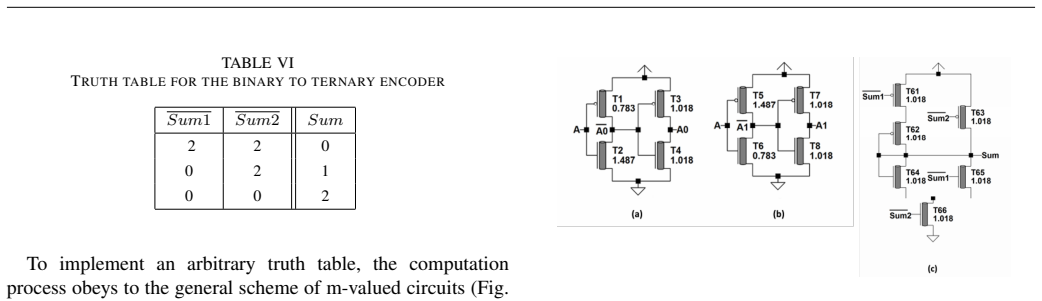
The load-bearing object is the refined cost equation C = k R(R - 1) log N / log R, where R is the radix, N the range to be represented, and R - 1 the number of threshold levels per digit. In the classical equation without the R - 1 factor, the minimum sits near e = 2.718; with the threshold factor, the curve rises with R and the minimum is at R = 2. The circuit comparisons then use a second quantitative tool: the information ratio log(3)/log(2) = 1.58, the maximum factor by which a ternary circuit's transistor count may exceed a binary circuit's and still be competitive. Every ternary design is checked against that ratio, and the decoder/encoder structure needed to implement arbitrary ternary truth tables is what pushes arithmetic circuits far over it.
What would settle it
A CNTFET ternary full adder with a transistor count at or below 1.58 times a binary full adder (roughly 28 transistors if the binary baseline is 18), built without an additional power supply and without a static dc path, would disprove the claim that ternary arithmetic circuits are always outperformed by binary ones.
Extended reading notes
Core claim
The paper's central claim is that the traditional proof of radix-3 optimality is invalid because it assumes the hardware cost of a digit is independent of how many voltage levels the digit must distinguish. Replacing the digit capacity R by R(R - 1), where R - 1 counts threshold levels, turns the cost curve from one with a minimum near e into one that rises monotonically, making radix 2 optimal. On the circuit side, the paper counts transistors for ternary designs taken from the CNTFET literature and compares them with binary implementations in the same technology. For half adders the ternary version needs 66 transistors versus 9 to 18 for binary; for full adders 124 versus 8 to 36; for a 5x5 ternary multiplier 6190 versus 2382 for an 8x8 binary one. Since the information ratio is only 1.58, any ratio above that means the ternary circuit uses more wires, area, and power, and the paper judges such circuits not competitive. The single three-transistor ternary inverter has a ratio of 1.5, but it achieves that only with an additional power supply and an always-on transistor creating a dc path, so it does not rescue the general claim.
Load-bearing premise
The argument collapses if hardware cost per digit does not actually grow with the number of threshold levels; the R(R - 1) term is assumed, not derived.
Editorial extensions
If this is right
- If the paper's cost model is right, there is no information-theoretic reason to prefer radix 3, and the classical e-radix argument should stop being cited as a motivation for ternary logic.
- For arithmetic building blocks in a MOSFET-like CNTFET technology, ternary circuits cannot compensate their transistor overhead by carrying more information per wire.
- The only ternary designs that meet the 1.58 bound are inverters, NAND gates, flip-flops, and SRAM cells built from the three-transistor inverter style, and those carry two serious drawbacks: an extra power supply and a static dc path.
- Ternary remains useful for special functions with three natural states, such as content-addressable memory storing 0, 1, and don't-care, but not as a general-purpose replacement for binary computation.
Reading between the lines
- The same threshold-level argument would apply to radix 4 and higher, so the classical equality C(2) = C(4) should not be read as saying binary and quaternary circuits have equal hardware cost.
- If a ternary arithmetic circuit style could be built with a transistor ratio below 1.58 without an extra power supply or dc path, the paper's 'always outperformed' conclusion would need qualification; the search for such a style is a natural test of how general the result is.
- Because the overhead comes from decoder/encoder logic and threshold levels rather than from carbon nanotubes specifically, the same conclusion is likely to hold in any technology where binary and ternary gates are built from the same transistor primitives.
Signed reviews
Editorial analysis
A structured set of objections, weighed in public.
Referee Report
Summary. The paper challenges the widely cited argument that radix e ≈ 2.718 (rounded to 3) is the optimal radix for computation. After reviewing Hurst's cost model C = k R log N / log R, the paper proposes a revised model C = k R (R-1) log N / log R, which makes R = 2 optimal. The bulk of the paper is an empirical comparison of ternary and binary circuits in MOSFET-like CNTFET technology, using published ternary designs, with transistor counts for inverters, NAND gates, half/full adders, multipliers, D flip-flops, and SRAM cells. The paper finds that only the 3-transistor inverter approach of [8] achieves a transistor-count ratio below the information ratio log(3)/log(2) ≈ 1.58, and only for basic gates and inverter-based circuits; arithmetic circuits are claimed to be always outperformed by binary counterparts.
Significance. The empirical transistor-count comparison is a useful and clearly presented data point that quantifies the circuit-level overhead of several published ternary designs relative to binary ones. The observation that the 1.58 information-ratio bound is rarely met is instructive and may be of interest to the multiple-valued logic community. However, the paper's central theoretical claim—that the e-radix demonstration is 'disproved'—rests on an unverified cost-model assumption rather than on a rigorous refutation. The strength of the stated conclusions therefore exceeds what the evidence supports. If the overclaims are softened and the cost model is presented as one plausible hypothesis, the paper could still be a meaningful contribution, but in its current form the central claim is not established.
major comments (2)
- [Section II.C, Eq. (2)] The replacement of Hurst's cost model C = k R log N / log R by C = k R (R-1) log N / log R is introduced by the assertion that hardware complexity is proportional to R-1, the number of threshold levels. No derivation from a concrete circuit model is provided, and the factor R-1 is not shown to hold across different gate types, arithmetic structures, or memories. Because the optimum of Eq. (2) is R=2 by construction, the 'disproof' of the e-radix result is not a refutation of Hurst's derivation but a demonstration that a different cost model yields a different optimum. The abstract and conclusion state that the demonstration 'is disproved'; this overstates what the paper actually shows. The contribution should be reframed as a sensitivity analysis of the cost model, or the disproof claim should be removed.
- [Section IV.B and IV.C] The comparison of ternary and binary arithmetic circuits uses a single design style for the ternary adders (the decoder/encoder approach from references [6] and [7]) and a single 1-trit multiplier design. The paper does not survey the broader space of published ternary adder and multiplier implementations, which may include pass-transistor or direct gate-level designs with different transistor counts. Consequently, the strong conclusion in the Abstract and Section V that 'for arithmetic circuits such as adders and multipliers, the ternary circuits are always outperformed by the binary ones' is not justified by the evidence presented. The claim should be restricted to the designs actually considered, or the paper should demonstrate that the selected designs are representative of the best available ternary implementations.
minor comments (4)
- [Abstract] The phrase 'e=2.718 rounded to 3' is imprecise: Hurst's demonstration concerns the continuous optimum at e, and the rounding to an integer radix is a separate step. Clarify the relationship between the continuous result and the integer radix.
- [Table VII] The row 'Ratio 3/2 1 1/3.67 1/7.3' is difficult to parse; the ratios should be written explicitly as 3.67 and 7.3, or as fractions 66/18 and 66/9, to avoid confusion.
- [Reference [5]] The URL 'http://dx.doi.org/10;1016/j.mejo.2015.09;018' uses semicolons instead of periods; this appears to be a typographical error.
- [Section II.C] The phrase 'Let's assume' should be replaced by a clear statement that Eq. (2) is presented as a hypothesis or alternative cost model, so that the reader immediately understands the conditional nature of the subsequent argument.
Circularity Check
The theoretical refutation of Hurst's e-radix result is forced by the cost model assumed in Eq. (2); the transistor-count comparison is independent but supports only a narrower claim.
-
self definitional
[Section II.C, Equation (2) and Figure 5]
"Let's assume that the hardware complexity is proportional to R − 1, i.e. the number of threshold levels. The new equation is: C = kR(R − 1) logN/logR ... C=f(R) is continuously rising and the optimal radix is 2."
The conclusion that the optimal radix is 2 is not derived from independent evidence; it is a direct algebraic consequence of replacing Hurst's per-digit cost R with R(R−1). The only justification offered is 'Let's assume...' plus the observation that one 4-valued inverter needs more thresholds. That example does not establish the global R(R−1) cost law across gates, adders, multipliers, and memories. The paper then presents this consequence as a 'refutation' of Hurst's e-optimality. Since the cost model is chosen so that R=2 minimizes C, the disproof claim reduces by construction to the assumption.
full rationale
The paper contains one clearly circular step: the theoretical 'refutation' of the e-radix result is not a refutation of Hurst's derivation but a replacement of Hurst's cost model with an unproved assumption. Equation (2) substitutes R(R−1) for R, and the optimum immediately becomes R=2. Because the R−1 factor is assumed rather than derived, the headline claim that Hurst's demonstration 'is disproved' reduces to the paper's own chosen input. The transistor-count comparisons in Sections IV are independent and self-contained against external benchmarks: they count transistors in published ternary and binary CNTFET circuits and compare against the 1.58 information ratio. This portion supports the narrower, credible conclusion that the selected ternary arithmetic circuits are not competitive, but it does not mathematically disprove the e-radix optimum. Thus the central theoretical claim is partially circular, while the empirical comparison provides independent content. The self-citations in the paper are not load-bearing: [9] is used for a general decoder-encoder scheme, and [17] is a concluding reference, but neither forces the main conclusion.
Assumptions & free parameters
assumptions (4)
- ad hoc to paper Hardware complexity is proportional to R-1, the number of threshold levels.
- domain assumption Transistor count is an adequate proxy for chip area, power, and interconnects when ratios are large.
- domain assumption The cited CNTFET ternary circuits are representative of the ternary approach.
- standard math Standard calculus and logarithm properties for minimizing cost functions.
Cite this review
Pith. "Pith review of Ternary circuits: why R=3 is not the Optimal Radix for Computation." pith.science (2026). https://pith.science/paper/HWMQPT5A
@misc{pith2026190806841,
  author       = {Pith},
  title        = {Pith review of: Ternary circuits: why R=3 is not the Optimal Radix for Computation},
  year         = {2026},
  howpublished = {\url{https://pith.science/paper/HWMQPT5A}},
  note         = {Machine review of arXiv:1908.06841}
}
read the original abstract
A demonstration that e=2.718 rounded to 3 is the best radix for computation is disproved. The MOSFET-like CNTFET technology is used to compare inverters, Nand, adders, multipliers, D Flip-Flops and SRAM cells. The transistor count ratio between ternary and binary circuits is generally greater than the log(3)/log(2) information ratio. The only exceptions concern a circuit approach that combines two circuit drawbacks (an additional power supply and a circuit conflict between transistors) and only when it implements circuits based on the ternary inverter. For arithmetic circuits such as adders and multipliers, the ternary circuits are always outperformed by the binary ones using the same technology.
Figures


Figures from the paper (14 more)







Reference graph
Works this paper leans on
-
[8]
Design of a ternary static memory cell using carbon nanotube based transistors
K. You and K. Nepal, “Design of a ternary static memory cell using carbon nanotube based transistors", in Micro and Nano Letters July 2011
work page 2011
-
[6]
CNTFET-Based Design of Ternary Logic Gates and Arithmetic Circuit
S. Lin, Y-B. Yin and F. Lombardi, “CNTFET-Based Design of Ternary Logic Gates and Arithmetic Circuit", IEEE Transactions on Nanotech- nology, V ol 10, No2, March 2011
work page 2011
-
[7]
High Performance Ternary Adder using CNTFET
S.K. Sahoo, G.Akhilesh, R. Sahoo and M. Mugkilar, “High Performance Ternary Adder using CNTFET", IEEE Transactions on Nanotechnology, V ol 16, No3, January 2017
work page 2017
-
[1]
Hurst, “Multiple-Valued Logic - Its Status and Its Future“, IEEE Trans
S.L. Hurst, “Multiple-Valued Logic - Its Status and Its Future“, IEEE Trans. on Computers, VOL. C-33, N o 12, December 1984
1984
-
[2]
Development of ternary computers at Moscow State Uni- versity
N. P. Brousentsov, S. P. Maslov , J. Ramil Alvarez, E.A. Zhogolev, “Development of ternary computers at Moscow State Uni- versity", Russian Virtual Computer Museum, http://www.computer- museum.ru/english/setun.htm
-
[3]
S. Rezaie, R.F.Mirzaee, K. Navi and O. Hashemipour, “New dynamic ternary minimum and maximum circuits with reduced switching activity and without any additional voltage sources", in Int. J. High Performance Systems Architecture, V ol. 5, No 3, 2015
work page 2015
-
[4]
Design of a Multi- digit Binary-to-Ternary Converters Based on CNTFETs
M. Shahangian, S.A. Hosseini, S.H.Pishgar Komleh, “Design of a Multi- digit Binary-to-Ternary Converters Based on CNTFETs", in Circuits, Systems and Signal Processing, https://doi.org/10.1007/s00034-018-0977- 3
-
[5]
Robust and energy-efficient carbon nanotube FET- based MVL gates: A novel design approach
F. Sharifi, et al., “Robust and energy-efficient carbon nanotube FET- based MVL gates: A novel design approach”, Microelectronic. J (2015), http://dx.doi.org/10;1016/j.mejo.2015.09;018
work page 2015
Show all 17 references
-
[9]
Comparison of binary and multivalued inte- grated circuits according to VLSI criteria
D.Etiemble and M.Israel, “Comparison of binary and multivalued inte- grated circuits according to VLSI criteria”, IEEE Computer, pp.28-42, April 1988
1988
-
[10]
Comparative Analysis of CNTFET and CMOS Logic Based Arithmetic Logic Unit
K.K. Nehru, T. Nagarjuna and G. Vijay, “Comparative Analysis of CNTFET and CMOS Logic Based Arithmetic Logic Unit", in Journal of Nano and Electronic Physics 9 (4), January 2017
2017
-
[11]
A review of multiple-valued memory technology
G. Gulak, “A review of multiple-valued memory technology”, Proceed- ings. 1998 28th IEEE International Symposium on Multiple- Valued Logic, Fukuoka, 1998, pp. 222-231
1998
-
[12]
A 16-level/Cell Dynamic Memory
M. Aoki et al, “A 16-level/Cell Dynamic Memory”, IEEE J. Solid State Circuits, V ol. SC-22, No 2, pp. 297-299, April 1987
1987
-
[13]
A 1 Gb DRAM for File Application
T. Sugibayashi, I. Naritake, A. Utsugi et al, “A 1 Gb DRAM for File Application”, ISSCC Digest of Technical Papers, pp. 254-255, Feb. 1995
1995
-
[14]
A 4-level Storage 4Gb DRAM
T. Murotani et al., “A 4-level Storage 4Gb DRAM”, ISSCC Digest of Technical Papers, pp.74-75, Feb. 1997
1997
-
[15]
A multilevel-Cell 32Mb Flash Memory
J. Bauer et al, “A multilevel-Cell 32Mb Flash Memory”, ISSCC Digest of Technical Papers, pp.132-133, Feb. 1995
1995
-
[16]
Jung et al, ”A 3.3 V 128 Mb Multi-Level Flash Memory for Mass Storage Applications”, ISSCC Digest of Technical Papers, pp.32-33, Feb
T. Jung et al, ”A 3.3 V 128 Mb Multi-Level Flash Memory for Mass Storage Applications”, ISSCC Digest of Technical Papers, pp.32-33, Feb. 1996
1996
-
[17]
Etiemble, Why M-Valued Circuits are restricted to a Small Niche”, in Journal of Multiple Valued Logic and Soft Computing, V ol
D. Etiemble, Why M-Valued Circuits are restricted to a Small Niche”, in Journal of Multiple Valued Logic and Soft Computing, V ol. 9, N o1, 2003. 9
2003
Reviewed August 14, 2026 · model on record in the stance chip above.
Discussion (0). Continue with ORCID to comment.