REVIEW 4 major objections 5 minor 1 cited by
Next generation direct RF sampling LLRF control and monitoring system for linear accelerators
T0 review · 4 major / 5 minor · reviewed 2026-08-04 · deepseek-v4-flash
Pith's one-line read Direct RF sampling with RFSoC hardware can generate and measure RF pulses for S-band and C-band linear accelerators without analog mixing, achieving pulse-to-pulse phase jitter of 166 fs at 16.45 MW.
desk verdict Legit engineering progress with an abstract that outruns the data: 166 fs open-loop jitter is above the 150 fs requirement, and the promised feedback is not yet implemented. read the letter →
The pith
A machine-rendered reading of the paper's core claim, the machinery that carries it, and where it could break.
The reading
What carries the argument
The key mechanism is direct RF sampling with the RFSoC's integrated data converters. ADCs sample the 5.712 GHz C-band signal at 2.4576 GSPS in a higher Nyquist zone, and DACs generate the RF at 5.89824 GSPS in the second Nyquist zone. All down-conversion, up-conversion, filtering, decimation, and feedback control are performed digitally inside the RFSoC, eliminating analog mixers and enabling arbitrary pulse shaping through firmware-defined baseband pulses.
What would settle it
Implement the feedback controller on the same C-band test stand and measure closed-loop phase jitter at the cavity forward coupler while delivering 16.45 MW. If the jitter does not drop below 150 fs, the central claim fails.
Extended reading notes
Core claim
The central claim is that an RFSoC-based LLRF system, using integrated ADCs and DACs sampling at higher Nyquist zones, can directly generate and digitize RF signals for S-band and C-band accelerating structures without any analog mixing circuits. In high-power tests, the system delivered 16.45 MW to a C-band structure and measured a phase jitter of 166 fs at the cavity forward coupler. The paper states that with feedback control still in development, the C3 requirement of 150 fs phase jitter is 'highly achievable'. For S-band, the same platform captured forward, reflected, and cavity-probe RF pulses at three drive levels, showing consistent magnitude and phase trends and revealing the cavity
Load-bearing premise
The claim that the C3 150 fs phase-jitter requirement is highly achievable rests on the assumption that the still-unimplemented feedback control loop will suppress the measured 166 fs open-loop jitter to below 150 fs; no closed-loop data or control-loop model is provided.
Editorial extensions
If this is right
- The C3 150 fs phase-jitter requirement is within reach once the real-time feedback control loop, currently in development, is added to the system.
- The same RFSoC platform can be reconfigured in software for different RF frequencies and bandwidths, serving both S-band and C-band stations and potentially other accelerator RF systems.
- Arbitrary digital pulse shaping enables techniques such as beam-loading compensation, pulse-compressor drive, and resonance-offset phase ramps, all demonstrated with high precision.
- The modular chassis with up to 16 input and 16 output channels plus flexible trigger and reference locking scales to accelerators with many RF stations, reducing size and cost compared to conventional LLRF systems.
Reading between the lines
- If the open-loop jitter decomposition holds, the dominant jitter source is the solid-state amplifier (adding ~70 fs), and a feedback loop may not fully correct such fast jitter; meeting 150 fs may also require a quieter amplifier or a faster correction path.
- The same direct-sampling architecture could be extended to other frequency bands (L-band, X-band) merely by changing the numerically controlled oscillator frequency and decimation, making a single hardware platform a universal LLRF front end.
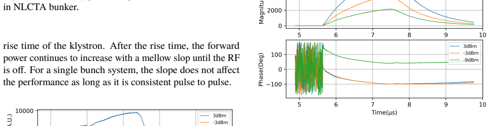
- The S-band measurements show cavity filling transients in reflection and probe signals, suggesting the NG-LLRF can double as an accelerator-structure diagnostic tool, not just a control system.
Editorial analysis
A structured set of objections, weighed in public.
Referee Report
Summary. The paper describes a next-generation low-level RF (LLRF) platform, NG-LLRF, built on an RFSoC with direct RF sampling and direct RF synthesis, eliminating conventional heterodyne analog mixing. The authors report high-power tests at SLAC on a C-band accelerating structure for the Cool Copper Collider (C3) and on an S-band structure at NLCTA. For C-band, they measure phase jitter at several circuit stages, culminating in 166 fs rms phase jitter at the cavity forward coupler at 16.45 MW, and argue that the C3 150 fs requirement is highly achievable once feedback is implemented. They also demonstrate arbitrary pulse shaping in C-band and show captured baseband pulses from S-band forward, reflected, and cavity-probe couplers, using an external signal source. The paper concludes that NG-LLRF is a promising compact, flexible platform for future and upgraded linear accelerators, with full feedback control and S-band DAC-driven operation still under development.
Significance. If the reported performance holds, the NG-LLRF platform would be a significant step toward compact, affordable, and scalable LLRF systems for future linear colliders and for upgrading existing S-band facilities. The direct RF sampling architecture removes a large amount of analog circuitry, and the demonstrated high-power C-band pulse-to-pulse stability and pulse-shaping flexibility are valuable experimental results. The hardware implementation on a single RFSoC, the modular chassis design, and the explicit path toward multi-channel operation are concrete engineering contributions. The strength of the paper is that it reports real high-power measurements with a working prototype, not simulations; this is a credible experimental advance. However, the significance is reduced by the mismatch between the abstract's claim of demonstrating 'considerably better than the requirements' and the data, which show open-loop jitter above the quoted C3 requirement, with no closed-loop demonstration or statistical error quantification. The S-band results are also preliminary and do not yet demonstrate direct DAC generation in that band.
major comments (4)
- [NG-LLRF FOR C-BAND LINACS / Pulse-to-pulse Stability with High-power Test] The central claim in the abstract that the platform 'demonstrated pulse-to-pulse fluctuation levels considerably better than the requirements' is not supported by the reported numbers. At 16.45 MW, the measured phase jitter at the cavity forward coupler is 166 fs, which is larger than the stated C3 requirement of 150 fs. The next sentence argues that 150 fs is 'highly achievable' with feedback, but the manuscript explicitly states that the real-time feedback control loop is still in progress and provides no control-loop model, plant transfer function, simulation, or closed-loop measurement. The open-loop value therefore cannot be used to claim that the requirement is already met; at most it supports a potential, not a demonstration.
- [NG-LLRF FOR C-BAND LINACS / Pulse-to-pulse Stability with High-power Test] The phase-jitter values are reported for 60 consecutive pulses with no error bars, no definition of how the rms is computed, and no discussion of systematic uncertainties. For an rms quantity estimated from 60 pulses, the standard error is approximately sigma/sqrt(2N) ≈ 15 fs for sigma = 166 fs, which is comparable to the 16 fs shortfall against the 150 fs C3 requirement. Without this statistical uncertainty, the comparison between 166 fs and 150 fs is not meaningful. The paper should report standard errors or confidence intervals and clearly state whether the jitter is measured pulse-to-pulse on the same phase reference or after any correction.
- [NG-LLRF FOR S-BAND LINACS / High-power Test Results] The S-band results do not support the claim of 'generating and measuring' RF pulses in both bands. In the reported tests, the RF pulses were generated by an external Hittite function generator and R&K power amplifier, while the NG-LLRF was used only to digitize and down-convert the signals. The manuscript explicitly says 'we used a Hittite function generator to generate a continuous wave (CW) RF signal around 2.856 GHz' and that the next step is to use the integrated DAC to generate the RF pulse. No quantitative pulse-to-pulse jitter or stability numbers are reported for S-band. The conclusions should be limited to what the S-band tests actually demonstrate: monitoring capability and consistency of baseband capture, not full LLRF control in S-band.
- [Abstract / Summary] The abstract and summary overstate the results relative to the body of the paper. The abstract says 'demonstrated pulse-to-pulse fluctuation levels considerably better than the requirements,' while the only explicit requirement quoted in the paper (C3 150 fs) is not met in the open-loop measurement. The summary states 'high pulse-to-pulse stability' without mentioning the open-loop vs. closed-loop distinction. The claims should be revised to state that the open-loop hardware shows a jitter level that is close to the requirement, and that achieving the requirement with feedback is a plausible projection, not a demonstrated result. This is a wording issue but one that affects the paper's central claim.
minor comments (5)
- [NG-LLRF FOR C-BAND LINACS / Pulse-to-pulse Stability with High-power Test] The text says 'the phase jitter with direct loopback is around 80ns when the DAC amplitude s 4000 or higher.' Given the context of Figure 2 and the surrounding fs-level discussion, '80ns' should almost certainly be '80 fs.' Please correct this typo.
- [NG-LLRF FOR S-BAND LINACS / High-power Test Setup] The frequency '2.856 GH' is missing the 'z' (should be GHz).
- [NG-LLRF FOR S-BAND LINACS / High-power Test Results] Figure 8's caption says 'forward coupler' but the figure and text describe the reflection coupler. The caption should read 'reflection coupler.' Also, 'NLTCA' appears in several captions and should be 'NLCTA.'
- [NG-LLRF FOR S-BAND LINACS / High-power Test Results] The text says 'the forward power continues to increase with a mellow slop until the RF is off.' This is likely a typo for 'slope'; the sentence is understandably unclear in its current form.
- [General] The paper would benefit from a table summarizing the phase-jitter contributions at each power level, including the 16.45 MW point, and from a clearer figure legend in Figure 2. Currently the reader must parse the text and figure together to reconstruct the individual contributions (82.8 fs, 5.6 fs, 7.0 fs).
Circularity Check
No significant circularity: the paper reports direct hardware measurements; the only self-referential element is a performance specification, not a derived result.
full rationale
The paper's central claims are empirical characterizations of an RFSoC-based LLRF platform through high-power tests. There is no mathematical derivation chain in which an output is equivalent to an input by construction. The phase jitter values (e.g., 166 fs at the cavity forward coupler) are measured from 60 consecutive pulses at defined stages; no fitted parameter is renamed as a prediction, and no normalization or equation forces the reported numbers. The statement that the C3 150 fs phase jitter requirement is 'highly achievable' with feedback is explicitly presented as an expectation, and the paper states the feedback loop is 'still in progress' and that 'more test results will be published' — this is an acknowledged extrapolation, not a circular derivation. The S-band results are likewise presented as preliminary ('We did not perform power mapping in this case'); the paper explicitly flags the missing full integration. Self-citations are used for background, architecture choices, and prior performance characterization, but the load-bearing evidence here is the in-paper measurement data, not an imported uniqueness theorem or an ansatz justified only by the authors' prior work. The C3 150 fs requirement is a specification from a concept paper, not a result produced by the present paper's methods, so citing it does not create circularity. Under the stated rules, unsupported extrapolation and missing error bars are correctness/statistical concerns, not circularity.
Assumptions & free parameters
assumptions (4)
- domain assumption Direct RF sampling in higher Nyquist zones with the RFSoC converters preserves the RF signal phase and amplitude faithfully.
- domain assumption The phase jitter measured across 60 consecutive pulses is representative of longer-term performance.
- domain assumption The C3 phase jitter requirement of 150 fs, taken from the same group's design concept paper [2], is the appropriate target.
- domain assumption The S-band structure is over-coupled, so the second reflection peak is interpreted accordingly.
Cite this review
Pith. "Pith review of Next generation direct RF sampling LLRF control and monitoring system for linear accelerators." pith.science (2026). https://pith.science/paper/IV3VTE5Y
@misc{pith2026250909905,
  author       = {Pith},
  title        = {Pith review of: Next generation direct RF sampling LLRF control and monitoring system for linear accelerators},
  year         = {2026},
  howpublished = {\url{https://pith.science/paper/IV3VTE5Y}},
  note         = {Machine review of arXiv:2509.09905}
}
read the original abstract
The low-level RF (LLRF) systems for linear accelerating structures are typically based on heterodyne architectures. The linear accelerators normally have many RF stations and multiple RF inputs and outputs for each station, so the complexity and size of the LLRF system grows rapidly when scaling up. To meet the design goals of being compact and affordable for future accelerators, or upgrading existing ones, we have developed and characterized the next generation LLRF (NG-LLRF) platform based on the RF system-on-chip (RFSoC) for S-band and C-band accelerating structures. The integrated RF data converters in RFSoC sample and generate the RF signals directly without any analogue mixing circuits, which significantly simplified the architecture compared with the conventional LLRF systems. We have performed high-power tests for the NG-LLRF with the S-band accelerating structure in the Next Linear Collider Test Accelerator (NLCTA) test facility at SLAC National Accelerator Laboratory and a C-band structure prototyped for Cool Cooper Collider (CCC). The NG-LLRF platform demonstrated pulse-to-pulse fluctuation levels considerably better than the requirements of the targeted applications and high precision and flexibility in generating and measuring the RF pulses. In this paper, the characterization results of the platform with different system architectures will be summarized and a selection of high-power test results of the NG-LLRF will be presented and analyzed.
Figures


Figures from the paper (5 more)




Forward citations
Cited by 1 Pith paper
-
Nanosecond Radio-Frequency Pulse Driven Photogun for Very Hard X-ray Free-electron Laser
A nanosecond RF pulse compression system enables a 500 MV/m photogun that delivers 60 nm emittance beams for mJ-scale 40 keV X-ray FEL operation.
Reference graph
Works this paper leans on
-
[1]
Next Generation LLRF Control Platform for CompactC-bandLinearAccelerator
C. Liuet al., “Next Generation LLRF Control Platform for CompactC-bandLinearAccelerator”,inLCWS2024,EPJWeb of Conferences, vol. 315, no. 4, p. 02008, 2024. doi:10.1051/epjconf/202431502008
arXiv 2024
-
[2]
E.Nannietal.,“ESPPUINPUT:C3withinthe"LinearCollider Vision" ”, 2025.arXivpreprintarXiv:2503.20829
arXiv 2025
-
[3]
Next generation LLRF control and monitoring system for S-band linear accelerators
C. Liuet al., “Next generation LLRF control and monitoring system for S-band linear accelerators”,Proc. 16th Interna- tional Particle Accelerator Conference, p. 3241-3244,2025. doi:10.18429/JACoW-IPAC25-THPS141
-
[4]
C. Liuet al., “Characterizing the performance of high-speed data converters for RFSoC-based radio astronomy receivers”, Monthly Notices of the Royal Astronomical Society, vol. 501, no.4, p.5096–5104, 2021. doi:10.1093/mnras/staa3895
-
[5]
C. Liuet al., “Development of General-purpose Digital Back- end for Single-dish Centimetre and Millimetre-wave Tele- scopes”,in 2022 3rd URSI Atlantic and Asia Pacific Radio Science Meeting (AT-AP-RASC). doi:10.23919/AT-AP-RASC54737.2022.9814190
arXiv 2022
-
[6]
Advanced RFSoC readout for space-based superconducting sensor arrays
S. Henderson, C. Liuet al., “Advanced RFSoC readout for space-based superconducting sensor arrays”,in Millimeter, Submillimeter,andFar-InfraredDetectorsandInstrumentation for Astronomy XI, vol. 12190, p. 339-355, 2022. doi:10.1117/12.2630412
-
[7]
Evaluating Direct RF Sampling Performance for RFSoC-based Radio-frequency Astronomy Receivers
C. Liuet al., “Evaluating Direct RF Sampling Performance for RFSoC-based Radio-frequency Astronomy Receivers”,in 2023 XXXVth General Assembly and Scientific Symposium of the International Union of Radio Science (URSI GASS). arXivpreprintarXiv:2309.08067
arXiv 2023
-
[8]
C. Liuet al., “Higher order nyquist zone sampling with rfsoc data converters for astronomical and high energy physics read- out systems”,in 2023 IEEE Nuclear Science Symposium and Medical Imaging Conference. arXivpreprintarXiv:2309.08640
arXiv 2023
Show all 14 references
-
[9]
Development of RFSoC-based direct sampling highlymultiplexedmicrowaveSQUIDreadoutforfutureCMB and submillimeter surveys
C. Liuet al., “Development of RFSoC-based direct sampling highlymultiplexedmicrowaveSQUIDreadoutforfutureCMB and submillimeter surveys”,in 2024 SPIE Astronomical Tele- scopes + Instrumentation.doi:10.1117/12.3019317
2024 doi
-
[10]
Direct rf sampling based LLRF control sys- tem for C-band linear accelerator
C. Liuet al., “Direct rf sampling based LLRF control sys- tem for C-band linear accelerator”,in IPAC’24 - 15th In- ternational Particle Accelerator Conference. p. 25-28, 2024. doi:10.18429/JACoW-IPAC2024-MOCN2
2024 doi
-
[11]
High-powertestofaC-bandlinearaccelerating structure with an RFSoC-based LLRF system
C.Liuetal.,“High-powertestofaC-bandlinearaccelerating structure with an RFSoC-based LLRF system”,Review of Scientific Instruments,vol. 96, no. 4, 2025. doi:10.1063/5.0258520
2025 doi
-
[12]
A Compact Low-level RF Control System for Advanced Concept Compact Electron Linear Accelerator
C. Liuet al., “A Compact Low-level RF Control System for Advanced Concept Compact Electron Linear Accelerator”, Review of Scientific Instruments,vol. 96, no. 9, 2025. doi:10.1063/5.0265666
2025 doi
-
[13]
High precision RF pulse shaping with direct RF sampling for future linear accelerators
C. Liuet al., “High precision RF pulse shaping with direct RF sampling for future linear accelerators”,Proc. 16th Inter- national Particle Accelerator Conference, p. 3237-3240,2025. doi:10.18429/JACoW-IPAC25-THPS140
2025 doi
-
[14]
LCLS LLRF upgrades to the SLAC linac
R. Akreet al., “LCLS LLRF upgrades to the SLAC linac ”,in 2007 IEEE Particle Accelerator Conference (PAC), p. 2421-2423, 2007
2007
Reviewed August 4, 2026 · model on record in the stance chip above.
Discussion (0). Sign in to comment.