REVIEW 4 major objections 4 minor 10 references
Linear motion (R-FLEX) for minature 6.2 mm pitch optical fiber position robots with polar (R-theta) kinematics
T0 review · 4 major / 4 minor · reviewed 2026-08-02 · deepseek-v4-flash
Pith's one-line read A four-leaf flexure stage claims sub-4 µm radial accuracy and a 400,000-target lifetime in a 5.8 mm package.
desk verdict A well-engineered radial flexure stage with credible prototype data, but the headline claim that it meets all key Spec-S5 requirements is ahead of the evidence: three of the headline metrics are full-robot allocations and were measured on the radial stage alone. read the letter →
The pith
A machine-rendered reading of the paper's core claim, the machinery that carries it, and where it could break.
The reading
What carries the argument
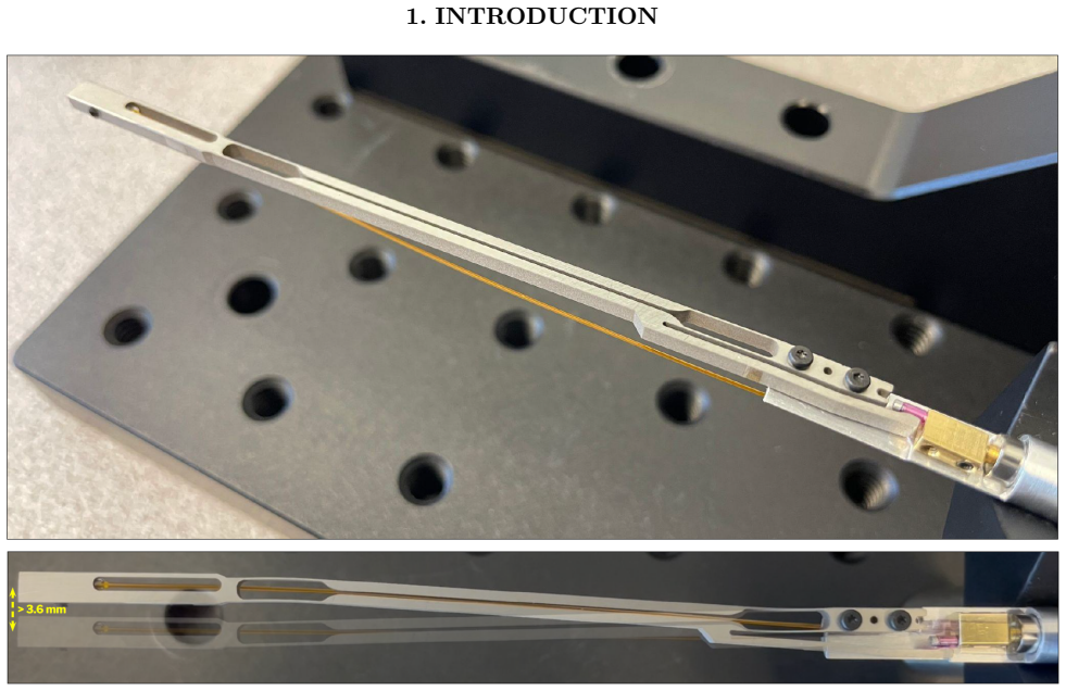
R-FLEX is a flexure mechanism: a 4 mm gearmotor rotates an eccentrically mounted cylindrical cam, which pushes a lever arm against four thin leaf flexures arranged as a parallel linear spring. The lever amplifies cam motion by a factor λ≈2.4, giving a fiber-tip radial position described by r(φ)=R_d λ (1−cos(φ+φ0))+r0, where R_d is the cam actuation radius, φ0 an angular offset, and r0 the radial origin. The four-leaf parallel-flexure arrangement is what produces nearly linear, low-backlash motion with very small fiber tilt; the kinematic map is what lets the robot command radial position from open-loop motor angle, with one optically measured correction move per target.
What would settle it
Take a new production unit, build its calibration map from a training set of target positions, then measure accuracy on a disjoint test set using an independent fiber-tip metrology such as a laser interferometer; if corrected RMS exceeds 5 µm or blind RMS exceeds 50 µm, the central accuracy claim would be refuted.
Extended reading notes
Core claim
The paper demonstrates that R-FLEX, a low-part-count flexure mechanism, converts small rotations at its base into nearly tilt-free radial motion at the fiber tip and, when paired with a theta-stage, provides the polar (R-θ) kinematics needed for dense fiber positioning. Prototype units measured by optical centroiding achieved corrected radial accuracy consistently below 4 µm RMS over a 3.9 mm travel range, with a maximum fiber tilt of 0.092 degrees and defocus of 42 µm, while accumulating more than 400,000 targeting operations per robot across operating and survival temperature limits. These values meet or exceed the preliminary requirements set for the complete R-θ robot, with the radial st
Load-bearing premise
The accuracy result depends on the assumption that the three-parameter calibration map, fit on a subset of the test targets, and the 0.3 µm optical centroiding measurements together faithfully represent the true fiber-tip position.
Editorial extensions
If this is right
- A single correction move suffices to bring radial accuracy below 4 µm RMS, so reconfiguration time can stay short enough for efficient survey operations.
- The radial stage alone consumes less than 20% of the full-robot fiber-tilt budget and about 84% of the defocus budget, leaving room for a companion theta-stage.
- With more than 400,000 targeting operations sustained across temperature extremes, the mechanism appears capable of meeting the 100,000-target lifetime requirement with margin.
- The parametric design pipeline can be re-run for different travel, stiffness, or defocus targets, so the same platform could serve other precision-positioning needs.
- Achieving the target density requires packing robots at 6.2 mm pitch; R-FLEX's 5.8 mm envelope makes that geometry possible without giving up the required radial travel.
Reading between the lines
- The reported accuracy is based on a per-robot calibration map fit over a subset of the very targets later used for the accuracy measurement; production deployments should validate on an independent target set before assuming sub-4 µm performance holds for every unit.
- Because the full-robot accuracy budget is 5 µm RMS and the radial stage alone achieves under 4 µm, the theta-stage must contribute less than roughly 2-3 µm RMS of error; that is a tight, testable constraint for the integrated robot.
- If the mechanism's linearity and low tilt hold, the same flexure geometry could be adapted for other small-envelope, high-repeatability positioning tasks, with fatigue life re-tested for each stress profile.
Editorial analysis
A structured set of objections, weighed in public.
Referee Report
Summary. The paper presents R-FLEX, a flexure-based radial positioning mechanism for next-generation fiber-fed spectrographs at 6.2 mm pitch. The mechanism converts small rotations of a cam, through a lever arm and four leaf flexures, into nearly tilt-free linear radial motion at the fiber tip. The authors describe the parametric design, FEA-based stress and fatigue analysis, fabrication of two prototypes, and measurements of radial accuracy via optical centroiding, together with defocus, fiber tilt, lifetime, and temperature performance. They report corrected radial accuracy better than 4 µm RMS, blind accuracy below 6 µm RMS, defocus of 42 µm, maximum fiber tilt of 0.092°, and more than 400,000 targeting operations per robot over operating and survival temperature extremes. The central claim is that these prototype results meet all key Spec-S5 requirements, leaving margin for the companion θ-stage, whose implementation and integration are still in progress.
Significance. If the results hold after integrated testing, the R-FLEX concept is a valuable contribution: a low-part-count, compact, tilt-free radial stage for high-density fiber positioning, with a parametric optimization pipeline that could generalize to other precision-positioning tasks. The direct measurements of accuracy, lifetime, and temperature robustness are commendable, and the FEA factors of safety provide useful design guidance. However, the paper's central claim overreaches the demonstrated scope: the full-robot requirements have not been validated as a system, and the accuracy evaluation is partially in-sample. These issues are fixable with clearer claims and additional validation, but they are load-bearing for the headline conclusion.
major comments (4)
- [Abstract; §1; §7; Table 2] The headline claim that R-FLEX prototypes "meet all key Spec-S5 requirements" is not supported by the evidence in the paper. Table 2 rows marked † (blind accuracy, corrected accuracy, defocus, fiber tilt) are requirements on the complete R-θ robot, yet the measurements are of the radial stage alone. Section 5.3 explicitly states that integrated validation is still in progress and that radial performance does not include θ-axis pointing. The margins are thin: corrected radial accuracy <4 µm RMS against a 5 µm full-robot budget leaves <1 µm for the θ-stage and integration; defocus 42 µm vs 50 µm leaves only 8 µm. The conclusion should be reworded to "the radial stage meets the portions of the Spec-S5 budgets that can be assessed without the θ-stage," or the integrated robot must be tested before claiming full compliance.
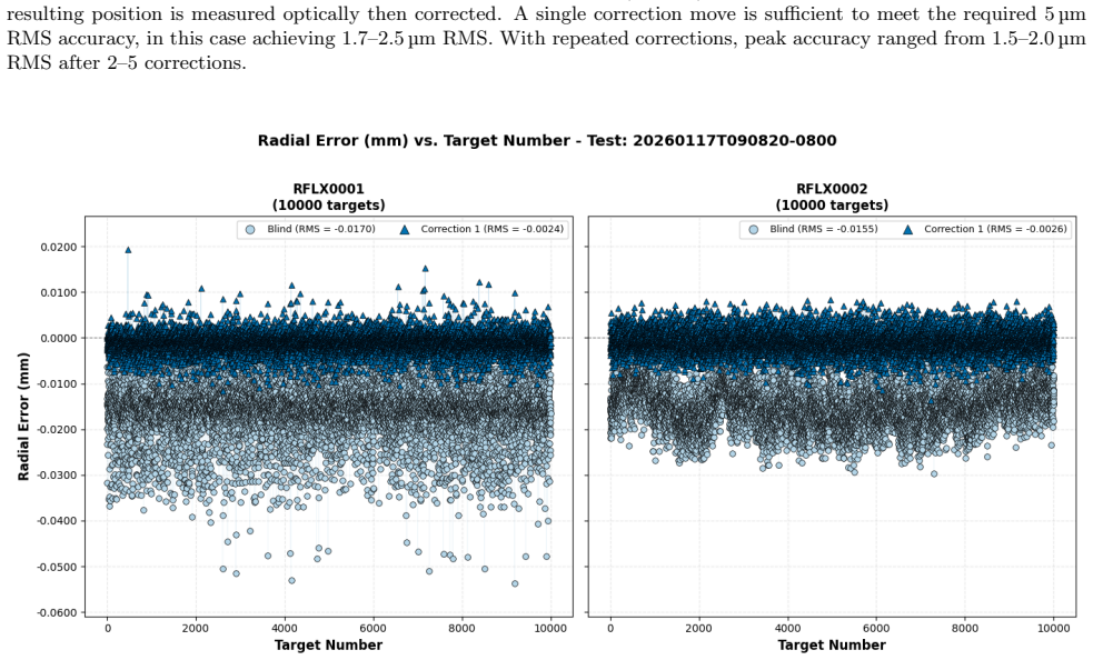
- [§5.1, Eq. (1), Figures 10–11] The accuracy statistics are computed against the same targets used to fit the three kinematic parameters (R_dλ, φ0, r0). This is an in-sample evaluation: systematic errors absorbed by the calibration fit are not reflected in the reported <4 µm RMS corrected accuracy. Please report accuracy on a held-out validation set (or use cross-validation) and clarify whether the optical centroiding (0.3 µm RMS) is treated as the true fiber-tip position. Without this, the residual and accuracy numbers mix calibration quality with mechanism repeatability.
- [§5.1, §5.2, Table 2] Defocus (42 µm) and fiber tilt (0.092°) were measured on only one prototype (RFLX0001) and in a mechanical configuration with a different travel range (4.2 mm vs 3.9 mm). While this is acknowledged in the text, the claim of meeting full-robot allocations for these quantities rests on a single sample. Either measure a second unit or clearly label these results as single-prototype values subject to unit-to-unit variation.
- [§5.3, Table 2] The claim that the radial stage "reserves margin" for the θ-stage presupposes an additive error budget whose allocation is nowhere stated. No table or equation decomposes the 5 µm/50 µm/0.5° full-robot requirements into radial and θ contributions. The reader cannot assess whether <4 µm vs 5 µm and 42 µm vs 50 µm leave enough margin. Please provide an explicit error-budget table, even in preliminary form, or temper the margin claim.
minor comments (4)
- [§5.1] The sentence "at cumulative counts of 399,743 and 387,643 operations" at the start of the two representative tests is confusing with the earlier statement that both robots exceeded 400,000 targets. Clarify whether the 400,000 figure includes subsequent tests or other runs not shown.
- [§2] The "maximum radial increment of ~0.015 µm" at the fiber tip is correct only after including the 337:1 gearbox reduction. Consider rewording to avoid apparent discrepancy with the 0.050 mm/deg sensitivity.
- [§5.1] Figures 10 and 11 are described as "two representative tests," but the text does not state which robot corresponds to each figure. Adding the unit ID would be useful.
- [Figure 5] The notation "R_v = R_1/2" is ambiguous; use R_v = R_1/2 or an explicit subscript to indicate halving.
Circularity Check
No significant circularity: the paper reports direct measurements of prototype hardware, and the fitted kinematic model is used only as a control map, not as the source of the claimed performance numbers.
full rationale
The paper's central claims are empirical measurements (optical centroiding, CMM defocus/tilt, cycle counts) of two prototype mechanisms, not derived predictions. Equation 1 is a three-parameter kinematic model fit to calibration data, and the paper explicitly separates the goodness of that calibration fit (Fig. 9 residuals) from the blind-move-plus-correction accuracy that is the reported performance metric. The corrected accuracy is dominated by mechanism repeatability and independent optical measurement, not by the fitted parameters. No claim reduces by construction to its own inputs: the fitted parameters (R_dλ, φ0, r0) are not renamed as predictions, and no uniqueness theorem or ansatz is imported from the authors' prior work. The self-citations (DESI, R-θ concept papers) provide context and heritage, not load-bearing support for the performance conclusions. The paper's own limitations section concedes that integrated R-θ validation is still in progress; that is a scope caveat about full-system requirements, not a circularity in the radial-stage measurements. Therefore no circular step meeting the evidentiary standard can be identified.
Assumptions & free parameters
free parameters (4)
- R_d·λ (cam radius × lever amplification) =
not stated numerically
- φ0 (angular offset) =
not stated
- r0 (radial origin) =
not stated
- Undershoot offset =
15 µm
assumptions (5)
- domain assumption Four leaf flexures behave as a parallel linear spring with negligible cross-coupling and no hysteresis beyond gearbox backlash.
- domain assumption Finite-element stress predictions with a conservative Ti-6Al-4V S-N curve bound fatigue life; 400,000-target endurance is taken as confirmation.
- domain assumption Optical centroiding of back-lit fibers (0.3 µm RMS repeatability) provides an unbiased measure of true fiber-tip position.
- ad hoc to paper Spec-S5 full-robot budgets (5 µm accuracy, 50 µm defocus, 0.5° tilt) can be decomposed additively, with the radial stage consuming a portion and the θ-stage the remainder.
- domain assumption Backlash and stick-slip are adequately suppressed by single-direction approach and small 0.1° motor steps, so open-loop commands plus one correction suffice.
Cite this review
Pith. "Pith review of Linear motion (R-FLEX) for minature 6.2 mm pitch optical fiber position robots with polar (R-theta) kinematics." pith.science (2026). https://pith.science/paper/JDZT44OQ
@misc{pith2026260713358,
  author       = {Pith},
  title        = {Pith review of: Linear motion (R-FLEX) for minature 6.2 mm pitch optical fiber position robots with polar (R-theta) kinematics},
  year         = {2026},
  howpublished = {\url{https://pith.science/paper/JDZT44OQ}},
  note         = {Machine review of arXiv:2607.13358}
}
read the original abstract
R-FLEX is a compact, low-part-count flexure-based radial positioning mechanism designed for the next generation of massively parallel fiber-fed spectroscopic telescope instruments. Current instruments such as the Dark Energy Spectroscopic Instrument (DESI) employ 5,000 robotic fiber positioners at 10.4 mm pitch, whereas future surveys require 2.5-3x higher packing density, necessitating new positioning technologies. The R-FLEX mechanism converts small rotations at the flexure base into large, nearly tilt-free radial motion at the fiber tip, achieving naturally low-backlash linear motion within a compact 5.8 mm diameter package. Coupled with a rotating theta-stage, this enables overlapping circular patrol areas at 6.2 mm pitch, as envisioned for projects like Spec-S5. Development proceeded through parametric modeling and optimization, finite element analysis, fabrication, and prototype testing. Prototype units characterized by optical centroiding achieved a corrected radial accuracy consistently better than 4 um RMS over a 3.9 mm travel range, with maximum fiber tilt 0.092 deg, defocus 42 um over the required range, and durability over more than 400,000 targets per robot across operating and survival temperature extremes. Preliminary Spec-S5 accuracy, defocus, and fiber tilt requirements are specified for the complete R-theta robot, and these radial-stage results exceed those requirements, leaving margin for the companion theta-stage. A parametric optimization pipeline makes R-FLEX a versatile, mass-producible platform that can be re-optimized for precision-positioning applications beyond Spec-S5. This offers the precision, compactness, and reliability needed to collect hundreds of millions of spectra for new studies of the large-scale structure of the universe.
Figures


Figures from the paper (10 more)




Reference graph
Works this paper leans on
-
[1]
The robotic multiobject focal plane system of the Dark Energy Spectroscopic Instrument,
Silber, J., et al., “The robotic multiobject focal plane system of the Dark Energy Spectroscopic Instrument,” The Astronomical Journal165(9) (2023). doi:10.3847/1538-3881/ac9ab1
-
[2]
25,000 optical fiber positioning robots for next-generation cosmology,
Silber, J., et al., “25,000 optical fiber positioning robots for next-generation cosmology,” in37th Annual Meeting of the American Society for Precision Engineering(2022). doi:10.48550/arXiv.2212.07908
-
[3]
A hybrid R-Theta fiber positioning robot using a piezoelectric bender for radial motion,
Schubnell, M., et al., “A hybrid R-Theta fiber positioning robot using a piezoelectric bender for radial motion,” inGround-based and Airborne Instrumentation for Astronomy XI, Proc. SPIE14149(2026). In press
2026
-
[4]
Dark Energy Spectroscopic Instrument (DESI) fiber positioner production,
Leitner, D., et al., “Dark Energy Spectroscopic Instrument (DESI) fiber positioner production,” inAdvances in Optical and Mechanical Technologies for Telescopes and Instrumentation III, Proc. SPIE10706, 1070669 (2018). doi:10.1117/12.2312228
-
[5]
The Large Sky Area Multi-Object Fiber Spectroscopic Telescope (LAMOST),
Cui, X.-Q., et al., “The Large Sky Area Multi-Object Fiber Spectroscopic Telescope (LAMOST),”Research in Astronomy and Astrophysics12, 1197–1242 (2012). doi:10.1088/1674-4527/12/9/003
-
[6]
Wang, S.-Y., et al., “Prime Focus Spectrograph (PFS) for Subaru Telescope: the optimization of convergence for Cobra positioners,” inGround-based and Airborne Instrumentation for Astronomy X, Proc. SPIE13096, 130962N (2024). doi:10.1117/12.3016931
-
[7]
A robotic Focal Plane System (FPS) for the Sloan Digital Sky Survey V,
Pogge, R. W., et al., “A robotic Focal Plane System (FPS) for the Sloan Digital Sky Survey V,” inGround-based and Airborne Instrumentation for Astronomy VIII, Proc. SPIE11447, 1144781 (2020). doi:10.1117/12.2561113
-
[8]
Performance of Echidna fiber positioner for FMOS on Subaru,
Akiyama, M., et al., “Performance of Echidna fiber positioner for FMOS on Subaru,” inAdvanced Op- tical and Mechanical Technologies in Telescopes and Instrumentation, Proc. SPIE7018, 70182V (2008). doi:10.1117/12.788968
Show all 10 references
-
[9]
LBNL fiber positioners for wide-field spectroscopy,
Schlegel, D., and Ghiorso, W., “LBNL fiber positioners for wide-field spectroscopy,” inAdvanced Op- tical and Mechanical Technologies in Telescopes and Instrumentation, Proc. SPIE7018, 701850 (2008). doi:10.1117/12.801673
2008 doi
-
[10]
Design and performance of an R-θfiber positioner for the BigBOSS instrument,
Silber, J., et al., “Design and performance of an R-θfiber positioner for the BigBOSS instrument,” inGround-based and Airborne Instrumentation for Astronomy IV, Proc. SPIE8450, 845038 (2012). doi:10.1117/12.926457
2012 doi
Reviewed August 2, 2026 · model on record in the stance chip above.
Discussion (0). Continue with ORCID to comment.