REVIEW 3 major objections 5 minor 14 references
An Insect-scale Self-sufficient Rolling Microrobot
T0 review · 3 major / 5 minor · reviewed 2026-08-14 · deepseek-v4-flash
Pith's one-line read A supercapacitor-powered 130 mg microrobot rolls freely at 27 mm/s after one charge.
desk verdict Genuinely novel double-ratchet mechanism and a working 130mg rolling bot, but the headline 2.5mW power figure cannot be right on the paper's own capacitor numbers. read the letter →
The pith
A machine-rendered reading of the paper's core claim, the machinery that carries it, and where it could break.
The reading
What carries the argument
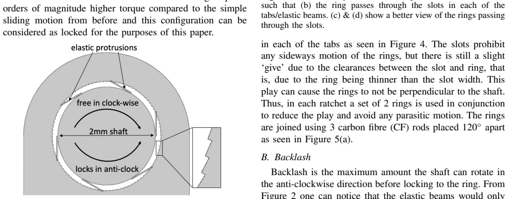
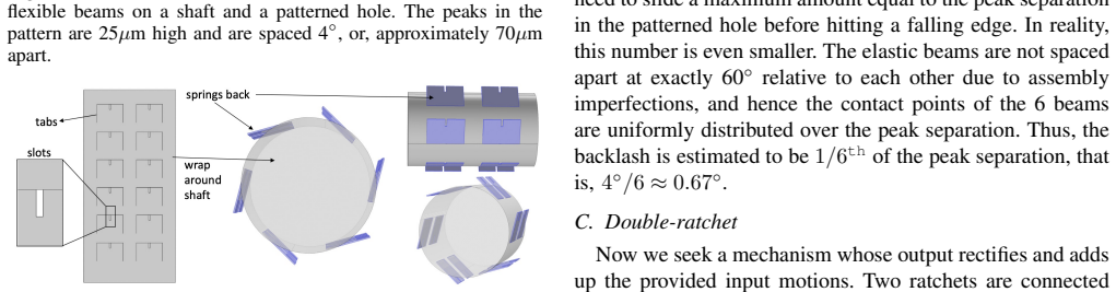
The double-ratchet is the load-bearing mechanism: two micro-ratchets joined on a common output shaft, each composed of an inner shaft with twelve flexible Kapton tabs that slide over laser-cut stainless-steel ring patterns in one rotational direction and lock against them in the other. The two ratchets are oriented oppositely, so the assembly rectifies oscillatory input into unidirectional rotation—a mechanical analog of an electrical diode bridge. This converts the small motions of an electromagnetic actuator (a magnet on a long moment arm moving inside a coil) into continuous rolling, while the long moment arm provides mechanical advantage to keep the required coil current near 0.5 mA.
What would settle it
Run the supercapacitor robot for ten or more charge-discharge cycles on a level surface while filming with a calibrated high-speed camera; if it does not consistently travel about 216 mm (27 mm/s × 8 s) with unidirectional wheel rotation, the self-sufficient rolling claim is contradicted.
Extended reading notes
Core claim
The central claim is that a milligram-scale double-ratchet can convert the small back-and-forth rotations of a low-voltage electromagnetic actuator into continuous, one-way wheel rotation. The mechanism uses two one-way ratchets on a common shaft: when the input ring turns clockwise, the rear ratchet locks to the shaft and drags it along; when the input turns counterclockwise, the rear ratchet slips while the front ratchet locks, holding the shaft still. A 20 Hz alternating drive thus accumulates all clockwise motion and discards all counterclockwise motion, producing a steadily turning output shaft. With this rectifier, a 130 mg robot carrying a supercapacitor, an op-amp oscillator, and an H-bridge rolls untethered for 8 seconds at 27 mm/s after charging to 3 V. The authors report this as the lightest and fastest self-sufficient rolling microrobot to date.
Load-bearing premise
The single 8-second rolling run of the supercapacitor version is treated as representative, with no repeated trials, error bars, or description of how displacement and speed were measured.
Editorial extensions
If this is right
- The double-ratchet can be driven by any oscillatory actuator, not just the electromagnetic coil-and-magnet used here, so the rectification principle transfers to other microrobot designs.
- Because Joule heating in the coil is the dominant power loss and is independent of oscillation frequency, the robot could be made to roll faster by raising the drive frequency with little change in power consumption.
- By moving anisotropy from the ground surface into the mechanism, the robot's rolling motion is much less sensitive to surface roughness than bristlebots are.
- A constant 1 V supply would reduce average power to about 0.6 mW, showing that the current 2.5 mW figure is largely an artifact of the supercapacitor's decaying voltage.
- With lighter wheels and supports (currently 40 mg), the total mass could drop well below 100 mg, and custom sub-1 V electronics would cut power further.
Reading between the lines
- Inference: Because the double-ratchet is a purely mechanical rectifier with no voltage or current floor, scaling the mechanism down to lighter robots may be limited by the weight of off-the-shelf electronics rather than by the actuator; a custom integrated circuit could push the approach to sub-100 mg or even sub-10 mg robots.
- Inference: The reported 8 s runtime and 27 mm/s speed trade off against the 11 mF supercapacitor's energy; replacing it with a larger or higher-voltage supercapacitor would extend the run at similar average power, with discharge rate and capacitor self-leakage becoming the new constraints.
- Inference: The robot's rolling gait couples only weakly to surface friction, which suggests it could serve as a controlled testbed for studying spike-surface interactions and wheel slip at millimeter scales, where bristlebot-style robots are too surface-sensitive.
Signed reviews
Editorial analysis
A structured set of objections, weighed in public.
Referee Report
Summary. This paper presents the design, fabrication, and testing of an 18mm x 8mm x 8mm rolling microrobot that uses low-voltage electromagnetic actuation (1-3V) and a newly proposed double-ratchet mechanism to convert small periodic input into continuous one-directional wheel rotation. Two versions are described: a 96mg laser-powered version, and a 130mg supercapacitor-powered version that is claimed to roll freely for 8s after a single charge at 27mm/s with wheels rotating at 300 deg/s and an average power of 2.5mW. The manuscript details the ratchet construction, actuator sizing, power electronics, mass budget, and three experiments: manual ratchet operation, a stationary laser-powered wheel-rotation test, and one rolling run of the supercapacitor version.
Significance. The proposed double-ratchet is a useful mechanical primitive, and the paper's component-level approach, with a measured starting-torque threshold, an explicit torque budget, and direct visual demonstration in Figs. 12 and 14, is a genuine strength. If the quantitative claims survive scrutiny, the supercapacitor version would be a notable untethered, self-powered insect-scale rolling robot. However, the headline numbers are not yet supported: the only supercapacitor demonstration is a single run with no measurement protocol or repeatability data, and the reported 2.5mW average power is internally inconsistent with the stated 11mF capacitor discharged from 3V to 1V in 8s. The central mechanism claim appears credible; the quantitative record claims require substantial reinforcement.
major comments (3)
- [Section III-C (and Abstract)] The stated energy budget is internally inconsistent. For C=11mF, discharging from 3V to 1V releases 0.5*C*(3^2-1^2)=44mJ, i.e., an average of 5.5mW over 8s, not 2.5mW. Conversely, 2.5mW*8s=20mJ would leave the capacitor at about 2.3V, not 1V. At least one of the capacitance, the voltage record, the duration, or the average power is wrong. Since the abstract advertises 2.5mW as a key feature and the same run underlies the speed and duration claims, the authors must provide the time-resolved capacitor voltage/current trace and a corrected power figure.
- [Section III-C] The entire quantitative evaluation of the supercapacitor version rests on a single run with no repeated trials, no error bars, and no description of how displacement, speed, wheel angular velocity, or power were measured. The text gives no tracking method, surface/floor conditions, or number of trials, and the real-time Figure 14 has no scale bar or time code. Because the lightest-and-fastest self-sufficient rolling microrobot claim depends on these measurements, repeated trials with a defined protocol and uncertainty reporting are required.
- [Sections II-E and II-F] The power and energy analysis omits the supercapacitor's 160 ohm internal resistance and any supply current drawn by the oscillator and H-bridge opamps; the statement that a constant 1V battery would give 0.6mW consumption is not reconciled with the energy available from the capacitor. A complete power budget from a logged voltage/current trace is needed to support the corrected average power claim.
minor comments (5)
- [Section II-C] The sentence 'resulting in the shaft adding adding up all the clockwise motions' contains a duplicated word and should be corrected.
- [Sections II-G and IV] The verb 'weights' should be 'weighs' in sentences such as 'The wheels ... weight 40mg' and in the description of the completed electronics unit.
- [Title and Abstract] The title calls the robot self-sufficient, but only the supercapacitor version is self-sufficient; the laser-powered version requires a manually pointed external laser. Please qualify the title or state the distinction more explicitly.
- [References] Reference [12] is cited for a 200mg supercapacitor-powered bristlebot crawling at 2mm/s, but the cited title is 'A fast-moving electrostatic crawling insect'; please confirm that this reference supports the stated weight, power source, and speed, and correct the citation if it does not.
- [Section II-E] The assumed friction coefficient mu_s=0.1 and the pre-deflection estimate delta_y=0.2mm are given without sensitivity analysis; a brief statement of how sensitive the starting-torque estimate is to these values would help the reader assess the robustness of the sizing calculation.
Circularity Check
No circularity: the mechanism and supercapacitor demonstration are self-contained; the power-bookkeeping inconsistency is an accounting error, not a circular derivation.
full rationale
The paper's derivation chain is self-contained. The double-ratchet is described geometrically and verified manually; the required coil current is computed from a measured starting torque (4.4 uNm), an FEA magnetic-field estimate (Bavg ~ 0.1T), and the stated 8mm moment arm, none of which are fitted to the observed 27mm/s or 300 deg/s output. The supercapacitor-run speed and duration are direct observations, not predictions from the model. The only notable defect is an internal accounting inconsistency: an 11mF capacitor discharging from 3V to 1V in 8s delivers 44mJ, i.e., 5.5mW average, not the stated 2.5mW (which over 8s corresponds to only 20mJ and would leave the capacitor near 2.3V). This is a measurement/reporting error in a headline quantity, not a circular step: no parameter is defined in terms of the claimed result, and no result is forced by a self-citation. Self-citations [3] and [4] support only the low-voltage actuation approach and are not load-bearing for the rolling mechanism or the supercapacitor demonstration.
Assumptions & free parameters
free parameters (3)
- static friction coefficient mu_s =
0.1 (assumed)
- beam pre-deflection delta_y =
0.2mm (estimated)
- average magnetic field Bavg =
approximately 0.1T from FEA
assumptions (4)
- standard math Cantilever beam stiffness formula k = E w t^3 / (4 l^3) applies to the elastic Kapton tabs.
- domain assumption The ratchet engages quasistatically at the 20Hz operating frequency without dynamic effects or wear.
- domain assumption The friction coefficient between Kapton tabs and the patterned steel ring is approximately 0.1.
- domain assumption The finite-element estimate Bavg of about 0.1T is representative of the average field seen by the coil during operation.
Cite this review
Pith. "Pith review of An Insect-scale Self-sufficient Rolling Microrobot." pith.science (2026). https://pith.science/paper/JLWRG67Y
@misc{pith2026190803283,
  author       = {Pith},
  title        = {Pith review of: An Insect-scale Self-sufficient Rolling Microrobot},
  year         = {2026},
  howpublished = {\url{https://pith.science/paper/JLWRG67Y}},
  note         = {Machine review of arXiv:1908.03283}
}
abstract
We design an insect-sized rolling microrobot driven by continuously rotating wheels. It measures 18mm$\times$8mm$\times$8mm. There are 2 versions of the robot - a 96mg laser-powered one and a 130mg supercapacitor powered one. The robot can move at 27mm/s (1.5 body lengths per second) with wheels rotating at 300$^\circ$/s, while consuming an average power of 2.5mW. Neither version has any electrical wires coming out of it, with the supercapacitor powered robot also being self-sufficient and is able to roll freely for 8 seconds after a single charge. Low-voltage electromagnetic actuators (1V-3V) along with a novel double-ratcheting mechanism enable the operation of this device. It is, to the best of our knowledge, the lightest and fastest self-sufficient rolling microrobot reported yet.
Figures


Figures from the paper (8 more)


Reference graph
Works this paper leans on
-
[1]
Controlled Flight of a Biologically Inspired, Insect-Scale Robot,
K. Ma, P. Chirarattanon, S. Fuller, and R.J. Wood, “Controlled Flight of a Biologically Inspired, Insect-Scale Robot,” Science, vol. 340, pp. 603-607, 2013
work page 2013
-
[2]
Liftoff of an Electromagnetically Driven Insect-Inspired Flapping-Wing Robot,
Y . Zou, W. Zhang, and Z. Zhang, “Liftoff of an Electromagnetically Driven Insect-Inspired Flapping-Wing Robot,” IEEE Transactions on Robotics, vol. 32, no. 5, October 2016
work page 2016
-
[3]
Milligram-scale Micro Aerial Vehicle Design for Low-voltage Operation,
P. Bhushan and C.J. Tomlin, “Milligram-scale Micro Aerial Vehicle Design for Low-voltage Operation,” IROS, Madrid, Spain, Oct. 2018
work page 2018
-
[4]
Design of the first sub-milligram flapping wing aerial vehicle,
P. Bhushan and C.J. Tomlin, “Design of the first sub-milligram flapping wing aerial vehicle,” MEMS, Seoul, South Korea, Jan. 2019
work page 2019
-
[5]
’Liftoff of a 190 mg Laser-Powered Aerial Vehicle: The Lightest Untethered Robot to Fly,
J. James, V . Iyer, Y . Chukewad, S. Gollakota, and S.B. Fuller, “’Liftoff of a 190 mg Laser-Powered Aerial Vehicle: The Lightest Untethered Robot to Fly,” IEEE Int. Conf. on Robotics and Automation, Brisbane, Australia, May 2018
work page 2018
-
[6]
A Review of Actuation and Power Electronics Options for Flapping-Wing Robotic Insects,
M. Karpelson, G-Y . Wei, and R.J. Wood, “A Review of Actuation and Power Electronics Options for Flapping-Wing Robotic Insects,” IEEE Int. Conf. on Robotics and Automation, Pasadena, CA, May 2008
work page 2008
-
[7]
Solar powered 10 mg silicon robot,
S. Hollar, A. Flynn, C. Bellew, and K.S.J. Pister, “Solar powered 10 mg silicon robot,” MEMS, Kyoto, Japan, 2003
work page 2003
-
[8]
First steps of a millimeter-scale walking silicon robot,
D.S. Contreras, D.S. Drew, and K.S.J. Pister, “First steps of a millimeter-scale walking silicon robot,” 19th International Conference on Solid-State Sensors, Actuators and Microsystems, 910-913, 2017
work page 2017
Show all 14 references
-
[9]
Miniaturized Rotary Actuators Using Shape Memory Alloy for Insect-Type MEMS Microrobot,
K. Saito, K. Iwata, Y . Ishihara, K. Sugita, M. Takato, and F. Uchikoba, “Miniaturized Rotary Actuators Using Shape Memory Alloy for Insect-Type MEMS Microrobot,” Micromachines, 7(4): 58, 2016
2016
-
[10]
A 3D-printed 1 mg legged microrobot running at 15 body lengths per second,
R.S. Pierre, W. Gosrich, and S. Bergbreiter, “A 3D-printed 1 mg legged microrobot running at 15 body lengths per second,” Hilton Head Solid- State Sensors, Actuators, and Microsystems Workshop, Hilton Head Island, SC, June 2018
2018
-
[11]
An untethered, electrostatic, globally controllable MEMS micro-robot,
B.R. Donald, C.G. Levey, C.D. McGray, I. Paprotny, and D. Rus, “An untethered, electrostatic, globally controllable MEMS micro-robot,” Journal of Microelectromechanical Systems, V ol. 15, No. 1, pp 1-15, 2006
2006
-
[12]
A fast-moving electrostatic crawling insect,
M. Qi, Y . Zhu, Z. Liu, X. Zhang, X. Yan, and L. Lin, “A fast-moving electrostatic crawling insect,” MEMS, Las Vegas, NV , Jan. 2017
2017
-
[13]
Single mask, large force, and large displacement electrostatic linear inchworm motors,
R. Yeh, S. Hollar, and K.S.J. Pister, “Single mask, large force, and large displacement electrostatic linear inchworm motors,” Journal of Microelectromechanical Systems, V ol. 11, No. 4, pp 330-336, 2002
2002
-
[14]
Optimized electrostatic inchworm motors using a flexible driving arm,
I. Penskiy and S. Bergbreiter, “Optimized electrostatic inchworm motors using a flexible driving arm,” Journal of Micromechanics and Microengineering, V ol. 23, No. 1, pp 1-12, 2012
2012
Reviewed August 14, 2026 · model on record in the stance chip above.
Discussion (0). Continue with ORCID to comment.