Dielectric insulated transmission lines in receiving antenna operation
Pith reviewed 2026-05-22 01:15 UTC · model grok-4.3
The pith
Exact expressions give the voltage a plane wave induces in any small dielectric two-conductor transmission line.
A machine-rendered reading of the paper's core claim, the machinery that carries it, and where it could break.
Core claim
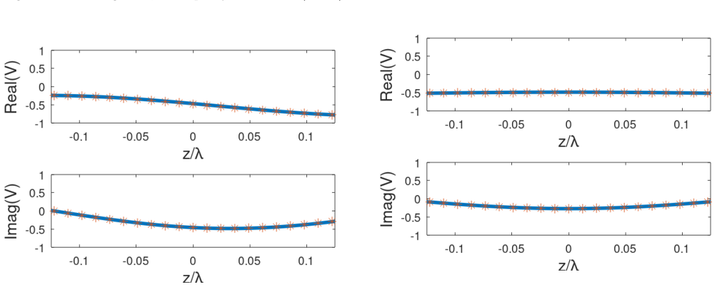
This work derives exact expressions for the voltage induced into a two conductors dielectrically isolated transmission line by a monochromatic incident plane wave from an arbitrary direction, at a given polarization. The transmission line cross section, consisting of the conductors and the dielectric material, may be of any shape, provided the cross section size is much smaller than the wavelength, so that the waves in radiation mode satisfy the quasi TEM condition. We calculate analytically the voltage along the transmission line for given end loads and compare the results with ANSYS HFSS simulation results. Our calculations are based on the knowledge of the radiation from such a transmis
What carries the argument
Radiation-absorption reciprocity applied to the known radiated fields of the quasi-TEM transmission line.
If this is right
- The voltage distribution along the line follows directly from the derived expressions for any chosen end loads.
- Analytic results agree closely with numerical simulations performed in ANSYS HFSS.
- The expressions remain valid for arbitrary incidence directions and polarizations under the size constraint.
Where Pith is reading between the lines
- The approach may allow rapid evaluation of induced voltages without repeated full-wave simulations for similar structures.
- Similar reciprocity techniques could apply to other receiving structures that support quasi-TEM modes.
- Extension to time-domain or broadband incident fields would require Fourier synthesis of the monochromatic solutions.
Load-bearing premise
The transmission line cross section must be much smaller than the wavelength so that the waves satisfy the quasi-TEM condition.
What would settle it
A full-wave simulation or measurement of induced voltage on a transmission line whose cross-section dimensions approach the wavelength, which would deviate from the analytic expressions.
Figures


read the original abstract
This work derives exact expressions for the voltage induced into a two conductors dielectrically isolated transmission line by a monochromatic incident plane wave from an arbitrary direction, at a given polarization. The transmission line cross section, consisting of the conductors and the dielectric material, may be of any shape, provided the cross section size is much smaller than the wavelength, so that the waves in radiation mode satisfy the quasi TEM condition. We calculate analytically the voltage along the transmission line for given end loads and compare the results with ANSYS HFSS simulation results. Our calculations are based on the knowledge of the radiation from such a transmission line, derived elsewhere and the radiation-absorption reciprocity.
Editorial analysis
A structured set of objections, weighed in public.
Referee Report
Summary. The manuscript derives exact expressions for the voltage induced into a two-conductor dielectrically isolated transmission line by a monochromatic incident plane wave from an arbitrary direction and given polarization. The transmission line cross-section (conductors plus dielectric) may be of arbitrary shape provided it is much smaller than the wavelength so that radiation-mode waves satisfy the quasi-TEM condition. Analytical voltage distributions along the line for specified end loads are obtained from prior radiation results via radiation-absorption reciprocity and are compared with ANSYS HFSS simulations.
Significance. If the claimed exact expressions are substantiated by the missing derivations and the HFSS comparisons confirm them within the stated quasi-TEM regime, the work would supply a useful analytical tool for receiving-antenna analysis of dielectric-insulated lines. The reciprocity route is a standard and efficient method that directly connects receiving and transmitting properties; successful validation would therefore extend existing transmitting-line results to the receiving case with clear engineering relevance.
major comments (2)
- [Abstract] Abstract: the central claim of 'exact expressions' and HFSS comparison is asserted without any derivation steps, error bounds, or quantification of the quasi-TEM approximation error. Reliance on radiation properties 'derived elsewhere' plus reciprocity leaves the support for the receiving-antenna result unverifiable from the manuscript text.
- [Abstract] Abstract: voltage calculations rest explicitly on external radiation results and reciprocity; this structure permits the receiving result to reduce directly to the transmitting case by the paper's own method, placing a high burden on any new content specific to receiving operation.
Simulated Author's Rebuttal
Thank you for the opportunity to respond to the referee's report. We address the major comments point by point below, clarifying the manuscript content and indicating where revisions will be made.
read point-by-point responses
-
Referee: [Abstract] Abstract: the central claim of 'exact expressions' and HFSS comparison is asserted without any derivation steps, error bounds, or quantification of the quasi-TEM approximation error. Reliance on radiation properties 'derived elsewhere' plus reciprocity leaves the support for the receiving-antenna result unverifiable from the manuscript text.
Authors: We agree the abstract is brief and omits explicit derivation steps or error bounds. The full manuscript details the reciprocity application to obtain induced voltages from the known radiation fields for arbitrary incidence and polarization. We have revised the abstract to outline the reciprocity steps and will add explicit discussion of quasi-TEM limits with quantitative comparison to HFSS results in the revised manuscript. revision: yes
-
Referee: [Abstract] Abstract: voltage calculations rest explicitly on external radiation results and reciprocity; this structure permits the receiving result to reduce directly to the transmitting case by the paper's own method, placing a high burden on any new content specific to receiving operation.
Authors: The receiving-specific content includes the setup for monochromatic plane-wave incidence from arbitrary directions and polarizations, leading to new analytical voltage distributions along the line for specified end loads. While reciprocity connects to prior radiation results, the receiving formulation and its validation against HFSS for the receiving case constitute distinct contributions not directly reducible to the transmitting analysis without this receiving context. revision: no
Circularity Check
No significant circularity identified
full rationale
The abstract states that calculations are based on radiation properties derived elsewhere plus radiation-absorption reciprocity, with the quasi-TEM condition as an explicit assumption for validity. No internal equations, derivation steps, or fitted parameters are provided in the available text, so no reduction of any claimed result to its own inputs by construction can be exhibited. Reciprocity is invoked as a general physical relation rather than a self-referential definition, and the external reference cannot be inspected for overlap or load-bearing status within this document. The work therefore presents no detectable circular steps under the specified criteria.
Axiom & Free-Parameter Ledger
axioms (1)
- domain assumption Cross-section size much smaller than wavelength so radiation modes satisfy quasi-TEM condition
Reference graph
Works this paper leans on
-
[1]
Radiation from free space TEM transmission lines
Ianconescu, R. and Vulfin, V., “Radiation from free space TEM transmission lines”, IET MICROW ANTENNA P 13(13), pp 2242-2255 (2019)
work page 2019
-
[2]
Radiation from Quasi-TEM insulated transmission lines
R. Ianconescu and V. Vulfin, “Radiation from Quasi-TEM insulated transmission lines”, IET Microwaves, IET MICROW ANTENNA P 13(6), pp. 761-773 (2019)
work page 2019
-
[3]
Free Space Transmission Lines in Receiving Antenna Operation
R. Ianconescu and V. Vulfin, “Free Space Transmission Lines in Receiving Antenna Operation”, Progress In Electromagnetics Research B, Vol. 109, 95-112, (2024)
work page 2024
-
[4]
Radiation Character- istics of a Transmission Line with a Side Plate
Nakamura, T., Takase, N. and Sato, R., “Radiation Character- istics of a Transmission Line with a Side Plate”, Electronics and Communications in Japan, Part 1, Vol. 89, No. 6, 2006
work page 2006
-
[5]
D. M. Pozar, Microwave Engineering, Wiley India Pvt., 2009
work page 2009
-
[6]
Frequency response of multiconductor trans- mission lines illuminated by an electromagnetic field
Paul, C. R.: “Frequency response of multiconductor trans- mission lines illuminated by an electromagnetic field”, IEEE Transactions on Electromagnetic Compatibility 4 (1976): 183- 190. 9
work page 1976
-
[7]
Vulfin, V., and Ianconescu, R., “Transmission of the maximum number of signals through a multiconductor transmission line without crosstalk or return loss: theory and simulation. ”, IET MICROW ANTENNA P 9.13 (2015): 1444-1452
work page 2015
-
[8]
Ianconescu R, Vulfin V. “Analysis of lossy multiconductor transmission lines and application of a crosstalk cancelling algorithm”, IET MICROW ANTENNA P 2017 Feb;11(3):394- 401
work page 2017
discussion (0)
Sign in with ORCID, Apple, or X to comment. Anyone can read and Pith papers without signing in.