REVIEW 3 major objections 4 minor 31 references
Simple, accurate lumped-element models of distributed resonators for superconducting quantum circuits
T0 review · 3 major / 4 minor · reviewed 2026-08-01 · deepseek-v4-flash
Pith's one-line read A single fitted LC pair can replace a distributed waveguide resonator in a quantum circuit model, keeping accuracy even under heavy capacitive loading.
desk verdict Useful, honest methods paper: the optimized single-LC fit genuinely beats LOM/Foster for the resonator's own mode and S-parameters, but the paper's own Fig. 4 shows the promised off-resonant load-shift prediction doesn't hold, so the modularity claim is only half-supported. read the letter →
The pith
A machine-rendered reading of the paper's core claim, the machinery that carries it, and where it could break.
The reading
What carries the argument
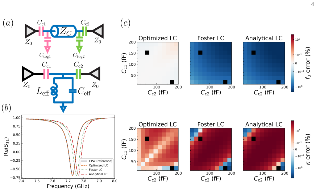
The key object is the fitted parallel LC pair (C_eff, L_eff) obtained by least-squares fitting the real parts of S11 and S22 of the transmission line model, with coupling capacitors explicitly included, over the window f0 ± 5κ. The fit is seeded by the standard analytic values and refines them to account for loading at both ends. This single-LC replacement is modular: it swaps out only the distributed element, leaving all lumped elements unchanged, so it can be cascaded.
What would settle it
Compute the frequency shift of a load resonator tuned far below the CPW mode (for example, 3 GHz versus 8.58 GHz) using the fitted LC model and compare to the exact distributed transmission line result; if the fractional error systematically exceeds a few percent across the coupling capacitance sweep, the off-resonant validity premise fails. The paper's own Fig. 4 shows one such case for load 2, where all models diverge from the CPW result.
Extended reading notes
Core claim
The central claim is that the effective capacitance and inductance of a distributed resonator are not intrinsic properties of the transmission line alone; they depend on the loading elements attached at its ports. By simulating the S-parameters of the transmission line with its coupling capacitors included, then fitting a single parallel LC pair within a window of f0 ± 5κ, the resulting model reproduces the microwave response of the full distributed circuit and predicts frequency shifts of attached resonant loads more accurately than established lumped models, in most tested cases.
Load-bearing premise
The single LC pair fitted only near the resonator's own resonance (within f0 ± 5κ) is taken to correctly represent the distributed line's impedance at far off-resonant frequencies, so that frequency shifts of attached loads can be predicted from the same LC values.
Editorial extensions
If this is right
- Designers can predict the shifted frequency and linewidth of a capacitively loaded CPW resonance to within about 0.5% and 3% of full-wave simulation in tested cases.
- The fitted LC model predicts frequency shifts of detuned resonant loads more accurately than analytic LOM and single-pole Foster synthesis, especially when loads are close to the CPW mode.
- Because the replacement is modular, a network with multiple distributed resonators can be modeled by fitting each one separately and cascading, without re-simulating the whole network.
- The method requires no full electromagnetic simulation of the distributed geometry, only a fast microwave network calculation of the effective transmission line.
Reading between the lines
- The same fitting procedure could likely be extended to higher modes by using multiple LC stages, and to inductive or mixed coupling by changing the port definitions, though the paper only demonstrates capacitive coupling.
- A natural test for adoption is benchmarking the fitted LC values against finite-element simulations for a range of geometries such as meandering lines and ground-plane discontinuities; the paper provides only a limited comparison.
- If the single-LC model remains accurate for far-detuned loads, it may allow black-box quantization of entire multi-resonator modules without EM simulation, making design-space search over circuit parameters much cheaper.
- The fit window f0 ± 5κ is a heuristic; a rigorous prescription for choosing the window from the resonator's quality factor would make the method more robust for very high-Q or very lossy devices.
Editorial analysis
A structured set of objections, weighed in public.
Referee Report
Summary. The paper addresses how to obtain quantizable lumped-element models for circuits containing distributed CPW resonators. The proposed 'optimized' model replaces the distributed transmission line with a single parallel LC, whose effective L and C are obtained by least-squares fitting of the S-parameters of the capacitively loaded CPW over a frequency window f0 ± 5κ. The authors compare this model with a standard analytical LOM and a Foster-synthesis BBQ model, reporting improved accuracy in resonance frequency and linewidth under heavy coupling (Fig. 2). They then test the model's ability to predict frequency shifts when resonant loads are attached (Figs. 3–4), and validate the CPW-mode frequency/linewidth against an independent HFSS simulation. An open-source package, simpleLOMs, is provided.
Significance. If fully realized, the method would offer a fast, modular, and intuitive path from layout to quantized circuit Hamiltonian, reducing reliance on full-wave EM simulation. The open-source implementation and the HFSS check are concrete strengths. However, the paper's own Fig. 4 shows that the model does not reliably predict shifts of off-resonant load modes—precisely the scenario where modular reuse of the fitted LC is most valuable. The central claim needs to be scoped more carefully; the current abstract and wording overstate the predictive power of a single LC fit.
major comments (3)
- [§3, Fig. 4, and abstract] The effective L and C are fitted only in the window f0 ± 5κ around the 8.58 GHz CPW mode. These values are then reused to predict shifts of load resonators at 5–6 GHz, which lie well outside this window. A single-pole LC cannot reproduce the distributed line impedance in that band, and the paper concedes in §3 that for load modes 'different approaches perform best... generally quite similar to each other and distinct from the true CPW model.' Because the modular workflow requires attaching off-resonant loads to the same fitted LC, the load-mode shifts are a key part of the claimed 'certain Hamiltonian parameters.' The current evidence supports only CPW-mode shift prediction, not the general modular claim. The authors should either restrict the predictive claim to the fitted resonance or add a broadband impedance check.
- [§2 (fit procedure) and Fig. 2] The accuracy of the optimized model in predicting f0 and κ is evaluated on exactly the same S-parameters that were used to least-squares fit C_eff and L_eff. This is therefore a goodness-of-fit result, not an independent predictive test. The HFSS comparison in the final paragraph is a welcome independent check, but it only covers the CPW-mode frequency and linewidth, not the off-resonant behavior. Please separate fitting capability from predictive capability and clarify that the 'beating out' claim refers to fitting performance on the training data, unless an out-of-sample test is provided.
- [§2, last paragraph (fit metric)] The fit minimizes least-squares error on the real parts of S11 and S22, with the justification that imaginary parts are determined by analyticity. For a passive, causal network the real part does determine the imaginary part via a Hilbert transform, but only when the real part is known over all frequencies; a local fit over f0 ± 5κ does not guarantee correct off-resonant imaginary parts. Since the subsequent predictions for resonant loads depend on the model's off-resonant impedance, the choice of fitting only the real parts in a finite window is load-bearing. Please report the fit residual, test whether fitting the full complex S-parameters changes the conclusions, and discuss the window dependence.
minor comments (4)
- [Eq. (1)] The typesetting of Eq. (1) is hard to read: 'nmZc' likely means n m Z_c, and the expressions for C_eff and L_eff appear to be interrupted by line breaks. Please reformat for clarity.
- [§1, text before Fig. 2] Typo: 'does is not self-consistent' should be 'is not self-consistent.'
- [Fig. 4 caption] The caption states that loads closer to the CPW mode are 'better improved by implementing the Optimized method,' while the main text says different approaches perform best depending on frequency. Please reconcile these statements and specify which approach wins in which region.
- [HFSS validation paragraph] Please provide more quantitative detail on the HFSS validation: the number of simulated geometries, the exact frequency range, and whether the 0.5%/3% errors refer to the CPW mode only or also to any load modes. Also mention whether the ground capacitances (10 fF) were included in the scikit-rf model.
Circularity Check
No significant circularity: L,C are openly fitted to S-parameters, and the predictive claims are tested out-of-sample.
full rationale
The model parameters are obtained by least-squares fitting S11/S22 in f0±5κ ('we vary L_eff and C_eff to fit the transmission line S parameters...'), so the Fig. 2 agreement is a fit residual, not an independent prediction. But the paper does not disguise this as a derivation; it explicitly describes the fitting procedure. The claims that matter for the abstract—predicting frequency shifts under resonant loads and matching HFSS—are out-of-sample: the same fitted LC is used with different terminations (resonant loads at 5–6 GHz; HFSS eigenmode simulation), so those agreements are not forced by the fit. The paper also states a limitation: 'A caveat is that we do not always see more accurate prediction of the shifts of the load resonators themselves... distinct from the true CPW model,' which bounds the predictive claim without indicating circularity. No load-bearing self-citation or imported uniqueness theorem appears; Eq. (2) is attributed to prior work but is a standard second-order perturbation formula and is not the basis of the method. Hence the derivation chain is self-contained apart from the transparently in-sample S-parameter validation; the observed load-mode inaccuracies are a correctness/scope limitation, not a circularity.
Assumptions & free parameters
free parameters (3)
- C_eff (effective capacitance) =
not reported (fit-dependent)
- L_eff (effective inductance) =
not reported (fit-dependent)
- fit_frequency_window (f0 ± 5κ) =
±5κ
assumptions (4)
- domain assumption The first mode of a capacitively loaded CPW can be represented by a single parallel LC circuit.
- domain assumption S-parameters of the distributed transmission line computed by scikit-rf are an accurate ground-truth model of the physical CPW.
- standard math Causality ensures the imaginary parts of S-parameters are fully determined by the real parts within the fit band.
- standard math The dispersive-shift formula χ_L ≈ g^2(1/(ω1−ω2) − 1/(ω1+ω2)) describes the simulated mode shifts.
Cite this review
Pith. "Pith review of Simple, accurate lumped-element models of distributed resonators for superconducting quantum circuits." pith.science (2026). https://pith.science/paper/MRD4C7EJ
@misc{pith2026260719543,
  author       = {Pith},
  title        = {Pith review of: Simple, accurate lumped-element models of distributed resonators for superconducting quantum circuits},
  year         = {2026},
  howpublished = {\url{https://pith.science/paper/MRD4C7EJ}},
  note         = {Machine review of arXiv:2607.19543}
}
abstract
Superconducting quantum circuit design is reliant on accurately mapping design parameters to a quantum Hamiltonian. Designers typically rely on computationally intensive finite-element electromagnetic simulations. However, effective circuit-level models can in principle capture much of the relevant physics for these systems, reducing the need for finite-element simulations. A barrier to implementing these simpler models has been the prevalence of distributed elements such as coplanar waveguides resonators in device designs. Techniques for modeling these distributed elements have been developed, but may be difficult to scale, reduce intuition, and give inaccurate results under strong coupling. In this work we describe a simple effective circuit-level model that faithfully reproduces the scattering parameters, and subsequently can predict certain Hamiltonian parameters, for a coupled, distributed element within a broader two-port network even up to strong coupling. Our approach does not explicitly require an electromagnetic simulation. Our model, along with other common lumped models used in black box quantization, is publicly available to researchers via an open-source code package, $\texttt{simpleLOMs}$.
Figures


Figures from the paper (1 more)

Reference graph
Works this paper leans on
-
[1]
E. M. Levenson-Falk and S. A. Shanto, ``A review of design concerns in superconducting quantum circuits,'' Materials for Quantum Technology, vol. 5, no. 2, p. 022003, 2025. [Online]. Available: http://dx.doi.org/10.1088/2633-4356/ade10d
-
[2]
U. Vool and M. Devoret, ``Introduction to quantum electromagnetic circuits,'' International Journal of Circuit Theory and Applications, vol. 45, no. 7, p. 897–934, 2017. [Online]. Available: http://dx.doi.org/10.1002/cta.2359
doi:10.1002/cta.2359 2017
-
[3]
S. Rasmussen, K. Christensen, S. Pedersen, L. Kristensen, T. Bækkegaard, N. Loft, and N. Zinner, ``Superconducting Circuit Companion ---an Introduction with Worked Examples ,'' PRX Quantum, vol. 2, no. 4, p. 040204, Dec. 2021. [Online]. Available: https://link.aps.org/doi/10.1103/PRXQuantum.2.040204
-
[4]
P. Krantz, M. Kjaergaard, F. Yan, T. P. Orlando, S. Gustavsson, and W. D. Oliver, ``A quantum engineer's guide to superconducting qubits,'' Applied Physics Reviews, vol. 6, no. 2, p. 021318, Jun. 2019. [Online]. Available: https://doi.org/10.1063/1.5089550
-
[5]
A. J. Kerman, ``Efficient numerical simulation of complex josephson quantum circuits,'' 10 2020
2020
-
[6]
T. Rajabzadeh, Z. Wang, N. Lee, T. Makihara, Y. Guo, and A. H. Safavi-Naeini, ``Analysis of arbitrary superconducting quantum circuits accompanied by a python package: Sqcircuit,'' Quantum, vol. 7, p. 1118, 2023. [Online]. Available: http://dx.doi.org/10.22331/q-2023-09-25-1118
-
[7]
H. Paik, D. I. Schuster, L. S. Bishop, G. Kirchmair, G. Catelani, A. P. Sears, B. R. Johnson, M. J. Reagor, L. Frunzio, L. I. Glazman, S. M. Girvin, M. H. Devoret, and R. J. Schoelkopf, ``Observation of high coherence in josephson junction qubits measured in a three-dimensional circuit qed architecture,'' Physical Review Letters, vol. 107, no. 24, Dec. 20...
-
[8]
A. Blais, R.-S. Huang, A. Wallraff, S. M. Girvin, and R. J. Schoelkopf, ``Cavity quantum electrodynamics for superconducting electrical circuits: An architecture for quantum computation,'' Physical Review A, vol. 69, no. 6, 2004. [Online]. Available: http://dx.doi.org/10.1103/PhysRevA.69.062320
Show all 31 references
-
[9]
Peruzzo, F
M. Peruzzo, F. Hassani, G. Szep, A. Trioni, E. Redchenko, M. Žemlička, and J. M. Fink, ``Geometric superinductance qubits: Controlling phase delocalization across a single josephson junction,'' PRX Quantum, vol. 2, no. 4, Nov. 2021. [Online]. Available: http://dx.doi.org/10.11...
2021 doi
-
[10]
X. You, J. A. Sauls, and J. Koch, ``Circuit quantization in the presence of time-dependent external flux,'' Physical Review B, vol. 99, no. 17, p. 174512, May 2019. [Online]. Available: https://link.aps.org/doi/10.1103/PhysRevB.99.174512
2019 doi
-
[11]
Z. K. Minev, T. G. McConkey, M. Takita, A. D. Corcoles, and J. M. Gambetta, ``Circuit quantum electrodynamics (cqed) with modular quasi-lumped models,'' 2021. [Online]. Available: https://arxiv.org/abs/2103.10344
2021 arXiv
-
[12]
Z. K. Minev, Z. Leghtas, S. O. Mundhada, L. Christakis, I. M. Pop, and M. H. Devoret, ``Energy-participation quantization of josephson circuits,'' npj Quantum Information, vol. 7, no. 1, Aug. 2021. [Online]. Available: http://dx.doi.org/10.1038/s41534-021-00461-8
2021 doi
-
[13]
S. E. Nigg, H. Paik, B. Vlastakis, G. Kirchmair, S. Shankar, L. Frunzio, M. H. Devoret, R. J. Schoelkopf, and S. M. Girvin, ``Black-box superconducting circuit quantization,'' Physical Review Letters, vol. 108, no. 24, 2012. [Online]. Available: http://dx.doi.org/10.1103/PhysR...
2012 doi
-
[14]
Zaccaria and A
S. Zaccaria and A. Gnudi, ``A method for the numerical analysis of hybrid lumped-distributed superconducting quantum circuits,'' 2025. [Online]. Available: https://arxiv.org/abs/2509.03651
2025
-
[15]
Chen, ``Addressing key scaling challenges in fixed-frequency transmon architectures,'' 2025
L. Chen, ``Addressing key scaling challenges in fixed-frequency transmon architectures,'' 2025. [Online]. Available: https://escholarship.org/uc/item/6644g65v
2025
-
[16]
Solgun, D
F. Solgun, D. P. DiVincenzo, and J. M. Gambetta, ``Simple Impedance Response Formulas for the Dispersive Interaction Rates in the Effective Hamiltonians of Low Anharmonicity Superconducting Qubits ,'' IEEE Transactions on Microwave Theory and Techniques, vol. 67, no. 3, pp. 92...
2019
-
[17]
Kunz, ``Simple lumped element models.'' [Online]
E. Kunz, ``Simple lumped element models.'' [Online]. Available: https://elizabethkunz.github.io/simpleLOMs/
-
[18]
M. D. Reed, B. R. Johnson, A. A. Houck, L. DiCarlo, J. M. Chow, D. I. Schuster, L. Frunzio, and R. J. Schoelkopf, ``Fast reset and suppressing spontaneous emission of a superconducting qubit,'' Applied Physics Letters, vol. 96, no. 20, May 2010. [Online]. Available: http://dx....
2010 doi
-
[19]
Jeffrey, D
E. Jeffrey, D. Sank, J. Mutus, T. White, J. Kelly, R. Barends, Y. Chen, Z. Chen, B. Chiaro, A. Dunsworth, A. Megrant, P. O’Malley, C. Neill, P. Roushan, A. Vainsencher, J. Wenner, A. Cleland, and J. M. Martinis, ``Fast accurate state measurement with superconducting qubits,'' ...
2014 doi
-
[20]
Schuster, ``Circuit quantum electrodynamics,'' 2007
D. Schuster, ``Circuit quantum electrodynamics,'' 2007. [Online]. Available: https://ui.adsabs.harvard.edu/abs/2007PhDT.......167S/abstract
2007
-
[21]
D. M. Pozar, Microwave engineering, 4th ed. 1em plus 0.5em minus 0.4em John Wiley & Sons, 2012
2012
-
[22]
This is appropriate when one wants to model capacitive couplings
Note that this expression is derived assuming that the voltage coordinate of the equivalent LC circuit is the same as the voltage at the voltage antinode of the transmission line. This is appropriate when one wants to model capacitive couplings. A different expression is found...
-
[23]
Shanto, A
S. Shanto, A. Kuo, C. Miyamoto, H. Zhang, V. Maurya, E. Vlachos, M. Hecht, C. W. Shum, and E. Levenson-Falk, ``Squadds: A validated design database and simulation workflow for superconducting qubit design,'' Quantum, vol. 8, p. 1465, 2024. [Online]. Available: http://dx.doi.or...
2024 doi
-
[24]
Solgun, D
F. Solgun, D. W. Abraham, and D. P. DiVincenzo, ``Blackbox quantization of superconducting circuits using exact impedance synthesis,'' Physical Review B, vol. 90, no. 13, Oct. 2014. [Online]. Available: http://dx.doi.org/10.1103/PhysRevB.90.134504
2014 doi
-
[25]
Arsenovic, J
A. Arsenovic, J. Hillairet, J. Anderson, H. Forsten, V. Ries, M. Eller, N. Sauber, R. Weikle, W. Barnhart, and F. Forstmayr, ``scikit-rf: An open source python package for microwave network creation, analysis, and calibration [speaker’s corner],'' IEEE Microwave Magazine, vol....
2022
-
[26]
We neglect the imaginary parts as these are analytical functions and so are fully determined by their real parts; likewise, S_ 12 and S_ 21 are fully determined by S_ 11 and S_ 22
-
[27]
M. S. Khalil, M. J. A. Stoutimore, F. C. Wellstood, and K. D. Osborn, ``An analysis method for asymmetric resonator transmission applied to superconducting devices,'' Journal of Applied Physics, vol. 111, no. 5, p. 054510, Mar. 2012. [Online]. Available: https://doi.org/10.106...
2012 doi
-
[28]
Probst, F
S. Probst, F. B. Song, P. A. Bushev, A. V. Ustinov, and M. Weides, ``Efficient and robust analysis of complex scattering data under noise in microwave resonators,'' Review of Scientific Instruments, vol. 86, no. 2, p. 024706, Feb. 2015. [Online]. Available: https://doi.org/10....
2015 doi
-
[29]
J. Koch, T. M. Yu, J. Gambetta, A. A. Houck, D. I. Schuster, J. Majer, A. Blais, M. H. Devoret, S. M. Girvin, and R. J. Schoelkopf, ``Charge-insensitive qubit design derived from the cooper pair box,'' Physical Review A, vol. 76, no. 4, Oct. 2007. [Online]. Available: http://d...
2007 doi
-
[30]
Available: https://elizabethkunz.github.io/simpleLOMs/
`` simpleLOMs .'' [Online]. Available: https://elizabethkunz.github.io/simpleLOMs/
-
[31]
Y. Lu, T. Zhao, A. Vallières, K. C. Smith, D. Weiss, X. You, Y. Zhang, S. Ganjam, A. Maiti, J. W. O. Garmon, S. Mundhada, Z. Huang, I. Mondragon-Shem, S. M. Girvin, J. Koch, and R. J. Schoelkopf, ``Systematic Construction of Time - Dependent Hamiltonians for Microwave - Driven...
2026
Reviewed August 1, 2026 · model on record in the stance chip above.
Discussion (0). Continue with ORCID to comment.