REVIEW 2 major objections 2 minor 37 references
A harmonic linearization method produces a single-input single-output sequence impedance model for droop-controlled inverters that captures mirror frequency coupling under unbalanced grids.
Reviewed by Pith at T0; open to challenge. T0 means a machine referee read the full paper against a public rubric. the ladder, T0–T4 →
Develops a single-input single-output sequence impedance model using harmonic linearization for droop-controlled inverters that captures mirror frequency coupling and unbalanced factors, with stability analysis via sensitivity methods and experimental validation.
T0 review reviewed 2026-06-28 challenge →
load-bearing objection The paper extends sequence impedance modeling to unbalanced conditions for droop inverters via harmonic linearization and adds sensitivity analysis, but the validation does not directly confirm that omitted coupling terms stay negligible. the 2 major comments →
Impedance Modeling and Stability Analysis of Droop-Controlled Inverter Under Unbalanced Power Grid Operating Conditions
The pith
A machine-rendered reading of the paper's core claim, the machinery that carries it, and where it could break.
The reading
Core claim
The paper develops a novel sequence impedance modeling scheme using harmonic linearization that produces a single-input single-output model for a droop-controlled inverter and the grid. By accounting for multi-frequency interactions inside the inverter, the method captures mirror frequency coupling effects and unbalanced factors to deliver a more accurate impedance representation for stability analysis.
What carries the argument
Single-input single-output sequence impedance modeling method based on harmonic linearization (HL) that accounts for multi-frequency interactions within the droop-controlled inverter.
Load-bearing premise
The harmonic linearization approach captures all relevant multi-frequency interactions and unbalanced factors without missing dynamics that would change the stability conclusions.
What would settle it
A hardware test under unbalanced grid conditions where the proposed impedance model predicts stability but the inverter exhibits sustained oscillations would falsify the model's accuracy.
If this is right
- Dominant factors influencing stability are identified via normalized sensitivity analysis combined with proportional weighting.
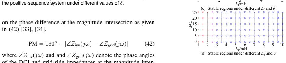
- The impacts of those dominant factors on stability margins are quantified under three typical unbalanced operating conditions using the Bode criterion.
- The modeling scheme is shown effective through validation on a constructed grid-connected droop-controlled experimental platform.
Where Pith is reading between the lines
- The modeling approach may apply to other grid-forming inverter types beyond droop control if their internal multi-frequency dynamics follow similar patterns.
- More accurate impedance models could support real-time stability monitoring tools in grids with high renewable penetration.
- The identified dominant factors suggest targeted control parameter adjustments could extend stability margins without full system redesign.
Editorial analysis
A structured set of objections, weighed in public.
Referee Report
Summary. The paper proposes a single-input single-output sequence impedance modeling method for droop-controlled inverters (DCI) based on harmonic linearization (HL). The method is claimed to comprehensively capture mirror frequency coupling effects (MFCE) and unbalanced factors by accounting for multi-frequency interactions inside the DCI and the connected grid. Dominant stability factors are identified via normalized sensitivity analysis and proportional weighting, and their impacts on stability margins are analyzed using the Bode criterion under three typical unbalanced operating conditions. The scheme is validated experimentally on a grid-connected droop-controlled platform.
Significance. If the HL-derived model is shown to be sufficiently accurate without truncation artifacts, the work would offer a practical SISO sequence-impedance tool for stability assessment of grid-forming inverters under unbalance, an increasingly relevant scenario with high renewable penetration. The experimental validation on a physical platform and the use of sensitivity analysis to isolate dominant factors are concrete strengths that could support reproducible application of the method.
major comments (2)
- [Modeling and linearization procedure (likely §III)] The central claim that HL 'comprehensively' captures MFCE and unbalanced factors (abstract) rests on retaining only selected sidebands; no demonstration is provided that omitted higher-order or cross-coupling terms remain negligible when the voltage unbalance factor increases, which directly affects the validity of the extracted impedance and subsequent Bode-based stability margins under the three reported conditions.
- [Experimental validation and results (likely §V)] Experimental validation is reported, yet the manuscript supplies neither quantitative error metrics between the HL model and measured impedances nor comparisons against existing multi-frequency or MIMO models, leaving the assertion of a 'more accurate' model unsubstantiated and preventing assessment of whether the retained HL terms suffice for the claimed stability conclusions.
minor comments (2)
- The abstract states the model is 'more accurate' without referencing any baseline model or error metric; a brief quantitative statement would strengthen the claim.
- Notation for sequence components and the precise harmonic truncation order used in the HL procedure should be defined consistently in the first modeling section to aid reproducibility.
Simulated Author's Rebuttal
We thank the referee for the detailed and constructive review. The comments identify important areas for strengthening the modeling justification and validation. We address each major comment below and will revise the manuscript accordingly.
read point-by-point responses
-
Referee: [Modeling and linearization procedure (likely §III)] The central claim that HL 'comprehensively' captures MFCE and unbalanced factors (abstract) rests on retaining only selected sidebands; no demonstration is provided that omitted higher-order or cross-coupling terms remain negligible when the voltage unbalance factor increases, which directly affects the validity of the extracted impedance and subsequent Bode-based stability margins under the three reported conditions.
Authors: We appreciate the referee's emphasis on rigorously justifying the truncation in the harmonic linearization. Section III derives the SISO sequence impedance by retaining the fundamental frequency and the primary positive- and negative-sequence sidebands that directly participate in mirror-frequency coupling under voltage unbalance. These terms are selected because higher-order harmonics are attenuated by the output filter and control bandwidths. Nevertheless, we agree that an explicit check of the neglected terms' magnitude versus unbalance factor would reinforce the claim of comprehensiveness. In the revision we will add a short analysis (new figure or appendix) quantifying the relative contribution of omitted cross-coupling terms for the unbalance factors used in the three operating conditions. revision: yes
-
Referee: [Experimental validation and results (likely §V)] Experimental validation is reported, yet the manuscript supplies neither quantitative error metrics between the HL model and measured impedances nor comparisons against existing multi-frequency or MIMO models, leaving the assertion of a 'more accurate' model unsubstantiated and preventing assessment of whether the retained HL terms suffice for the claimed stability conclusions.
Authors: We concur that quantitative error metrics and a clearer positioning relative to MIMO approaches would strengthen the validation section. The experimental results in Section V compare the HL-derived impedance curves with measurements on the physical platform, but we did not report numerical error statistics. In the revised manuscript we will add root-mean-square error and maximum deviation figures between the modeled and measured impedance magnitude and phase over the relevant frequency range. Direct side-by-side comparison with a full MIMO model is outside the paper's scope (our goal is a practical SISO tool), yet we will include a brief discussion noting that the retained sidebands capture the dominant dynamics observed in the MIMO representation for the studied unbalance levels, thereby supporting the accuracy claim for the intended stability analysis. revision: yes
Circularity Check
No circularity; standard HL application to unbalanced regime is self-contained
full rationale
The derivation applies harmonic linearization (an established small-signal technique) to derive sequence impedances for a droop-controlled inverter under unbalance, then performs sensitivity analysis and Bode stability checks. No equations reduce a claimed prediction to a fitted input by construction, no self-citation chain carries the central modeling claim, and no ansatz or uniqueness result is imported from the authors' prior work. The experimental platform validation is external to the modeling steps themselves. This is the normal case of an application paper whose core steps remain independent of the target conclusions.
Axiom & Free-Parameter Ledger
Cite this review
Pith. "Pith review of Impedance Modeling and Stability Analysis of Droop-Controlled Inverter Under Unbalanced Power Grid Operating Conditions." pith.science (2026). https://pith.science/paper/OFBSOHT6
@misc{pith2026260603104,
  author       = {Pith},
  title        = {Pith review of: Impedance Modeling and Stability Analysis of Droop-Controlled Inverter Under Unbalanced Power Grid Operating Conditions},
  year         = {2026},
  howpublished = {\url{https://pith.science/paper/OFBSOHT6}},
  note         = {Machine review of arXiv:2606.03104}
}
read the original abstract
With the growing integration of renewable energy sources into power grids, the risks of oscillation caused by interactions between grid-tied inverters and the grids are becoming increasingly prominent. Although existing studies have made significant progress in inverter modeling and oscillatory stability analysis, most of them do not sufficiently consider complex mirror frequency coupling effects (MFCE) under unbalanced operating conditions, leading to unreliable models and erroneous stability analysis results. To address this inadequacy, this work develops a novel sequence impedance modeling scheme that can be widely applied to unbalanced operating conditions. In particular, taking a representative type of grid-forming inverter for instance, i.e., droop-controlled inverter (DCI), a single-input single-output sequence impedance modeling method based on harmonic linearization (HL) is proposed to comprehensively model both a given DCI and the connected grid. By accounting for multi-frequency interactions within the DCI, this method captures MFCE and unbalanced factors, leading to a more accurate impedance model. Further, the dominant factors influencing system stability are identified with a combination of normalized sensitivity analysis and proportional weighting. Finally, the detailed impacts of these dominant factors on system stability margin under three typical unbalanced operating conditions are analyzed through the Bode criterion. The effectiveness and reliability of the whole scheme proposed in this work are validated on the constructed grid-connected droop-controlled experimental platform.
Figures




Reference graph
Works this paper leans on
-
[1]
Improving small-signal stability of grid-connected inverter under weak grid by decoupling phase-lock loop and grid impedance,
X. Linet al., “Improving small-signal stability of grid-connected inverter under weak grid by decoupling phase-lock loop and grid impedance,” IEEE Trans. Ind. Electron., vol. 69, no. 7, pp. 7040–7053, 2021
2021
-
[2]
Ercot experience screening for sub-synchronous control interaction in the vicinity of series capacitor banks,
J. Adamset al., “Ercot experience screening for sub-synchronous control interaction in the vicinity of series capacitor banks,” inProc. IEEE Power Energy Soc. Gen. Meeting. IEEE, 2012, pp. 1–5
2012
-
[3]
New microprocessor based relay to monitor and protect power systems against sub-harmonics,
K. Narendraet al., “New microprocessor based relay to monitor and protect power systems against sub-harmonics,” inProc. IEEE Electr . Power Energy Conf.IEEE, 2011, pp. 438–443
2011
-
[4]
Stability analysis of ssr in multiple wind farms connected to series-compensated systems using impedance network model,
H. Liuet al., “Stability analysis of ssr in multiple wind farms connected to series-compensated systems using impedance network model,”IEEE Trans. Power Syst., vol. 33, no. 3, pp. 3118–3128, 2017
2017
-
[5]
An oscillatory stability criterion based on the unifieddq-frame impedance network model for power systems with high-penetration renewables,
H. Liu, X. Xie, and W. Liu, “An oscillatory stability criterion based on the unifieddq-frame impedance network model for power systems with high-penetration renewables,”IEEE Trans. Power Syst., vol. 33, no. 3, pp. 3472–3485, 2018
2018
-
[6]
Partition-based network equivalent method for power system subsynchronous oscillation analysis,
C. Wang, W. Zheng, Z. Wanget al., “Partition-based network equivalent method for power system subsynchronous oscillation analysis,”J. Mod. Power Syst. Clean Energy, vol. 12, no. 1, pp. 313–320, 2023
2023
-
[7]
Adaptive spatial-temporal graph learning-enabled short- term voltage stability assessment against time-varying topological con- ditions,
C. Denget al., “Adaptive spatial-temporal graph learning-enabled short- term voltage stability assessment against time-varying topological con- ditions,”IEEE Trans. Power Syst., pp. 1–13, 2026, early access
2026
-
[8]
Impedance characteristic analysis and stability improvement method for dfig system within pll bandwidth based on different reference frames,
B. Hu, H. Nian, M. Liet al., “Impedance characteristic analysis and stability improvement method for dfig system within pll bandwidth based on different reference frames,”IEEE Trans. Ind. Electron., vol. 70, no. 1, pp. 532–543, 2022
2022
-
[9]
A systematic stability enhancement method for microgrids with unknown-parameter inverters,
Y . Li, X. Wu, Z. Shuaiet al., “A systematic stability enhancement method for microgrids with unknown-parameter inverters,”IEEE Trans. Power Electron., vol. 38, no. 3, pp. 3029–3043, 2022
2022
-
[10]
Analysis of interactive behavior and stability of low-voltage multiterminal DC system under droop control modes,
W. Deng, W. Pei, Q. Wuet al., “Analysis of interactive behavior and stability of low-voltage multiterminal DC system under droop control modes,”IEEE Trans. Ind. Electron., vol. 69, no. 7, pp. 6948–6959, 2021
2021
-
[11]
Comparison of dynamic characteristics between virtual synchronous generator and droop control in inverter- based distributed generators,
J. Liu, Y . Miura, and T. Ise, “Comparison of dynamic characteristics between virtual synchronous generator and droop control in inverter- based distributed generators,”IEEE Trans. Power Electron., vol. 31, no. 5, pp. 3600–3611, 2015
2015
-
[12]
Small-signal modeling and stability anal- ysis of hybrid AC/DC microgrids,
Z. Li and M. Shahidehpour, “Small-signal modeling and stability anal- ysis of hybrid AC/DC microgrids,”IEEE Trans. Smart Grid, vol. 10, no. 2, pp. 2080–2095, 2017
2080
-
[13]
Sequence impedance prediction for grid-connected converters based on Bi-LSTM,
S. Li, R. Kong, F. Blaabjerget al., “Sequence impedance prediction for grid-connected converters based on Bi-LSTM,”IEEE Trans. Power Electron., 2025, early access
2025
-
[14]
Small-signal modeling and stability prediction of parallel droop-controlled inverters based on terminal char- acteristics of individual inverters,
S. Wang, Z. Liu, J. Liuet al., “Small-signal modeling and stability prediction of parallel droop-controlled inverters based on terminal char- acteristics of individual inverters,”IEEE Trans. Power Electron., vol. 35, no. 1, pp. 1045–1063, 2019
2019
-
[15]
Stability-oriented droop coefficients region identifi- cation for inverters within weak grid: An impedance-based approach,
R. Wanget al., “Stability-oriented droop coefficients region identifi- cation for inverters within weak grid: An impedance-based approach,” IEEE Trans. Syst., Man, Cybern.: Syst., vol. 51, no. 4, pp. 2258–2268, 2020
2020
-
[16]
Virtual oscillator grid-forming inverter stability analysis based on impedance model,
S. Guo, H. Ye, J. Yanget al., “Virtual oscillator grid-forming inverter stability analysis based on impedance model,” inProc. IEEE 7th Int. Electr . Energy Conf. (CIEEC). IEEE, 2024, pp. 4633–4638
2024
-
[17]
Impedance modeling and stability analysis of grid-forming converters,
R. Zhao, X. Yang, A. Weiet al., “Impedance modeling and stability analysis of grid-forming converters,” inProc. IEEE Transp. Electrif. Conf. Expo (ITEC). IEEE, 2024, pp. 1–6
2024
-
[18]
Sequence impedance modeling of grid-forming inverters,
W. Yan, S. Shah, V . Gevorgianet al., “Sequence impedance modeling of grid-forming inverters,” inProc. IEEE Power Energy Soc. Gen. Meet. (PESGM). IEEE, 2021, pp. 1–5
2021
-
[19]
Uni- fied sequence impedance models of synchronous generator-and virtual oscillator-based grid-forming converters,
M. A. Elshenawy, A. Radwan, and Y . A.-R. I. Mohamed, “Uni- fied sequence impedance models of synchronous generator-and virtual oscillator-based grid-forming converters,”IEEE Trans. Power Del., vol. 39, no. 1, pp. 56–70, 2023
2023
-
[20]
Modeling and suppression strategy research on frequency coupling of droop control,
X. Rong, X. Wang, Y . Liet al., “Modeling and suppression strategy research on frequency coupling of droop control,” inProc. IEEE Int. Power Electron. Appl. Symp. (PEAS). IEEE, 2023, pp. 2029–2034
2023
-
[21]
Analysis and weakening of sequence impedance coupling in grid-forming converters,
M. A. Elshenawy and others., “Analysis and weakening of sequence impedance coupling in grid-forming converters,”IEEE Trans. Power Del., vol. 39, no. 6, pp. 3292–3304, 2024
2024
-
[22]
Sequence impedance modeling of droop- controlled inverter,
Y . Hu, J. Wang, B. Liuet al., “Sequence impedance modeling of droop- controlled inverter,” inProc. 8th Renew. Power Gener . Conf. (RPG). IET, 2019, pp. 1–5
2019
-
[23]
Harmonic transfer-function-based αβ-frame SISO impedance modeling of droop inverters-based islanded microgrid with unbalanced loads,
J. Guo, Z. Meng, Y . Chenet al., “Harmonic transfer-function-based αβ-frame SISO impedance modeling of droop inverters-based islanded microgrid with unbalanced loads,”IEEE Trans. Ind. Electron., vol. 70, no. 1, pp. 452–464, 2022
2022
-
[24]
Input impedance modeling of multipulse rectifiers by harmonic linearization,
J. Sun, Z. Bing, and K. J. Karimi, “Input impedance modeling of multipulse rectifiers by harmonic linearization,”IEEE Trans. Power Electron., vol. 24, no. 12, pp. 2812–2820, 2009
2009
-
[25]
Admittance-based stability analysis of current-controlled VSG considering the frequency coupling charac- teristics,
H. Wang, Z. Xie, Y . Chenet al., “Admittance-based stability analysis of current-controlled VSG considering the frequency coupling charac- teristics,”IEEE J. Emerg. Sel. Topics Power Electron., vol. 11, no. 1, pp. 1191–1202, 2022
2022
-
[26]
Modeling, stability, and design of the single-phase SOGI-based phase-locked loop considering the frequency feedback loop effect,
J. Xuet al., “Modeling, stability, and design of the single-phase SOGI-based phase-locked loop considering the frequency feedback loop effect,”IEEE Trans. Power Electron., vol. 38, no. 1, pp. 987–1002, 2022
2022
-
[27]
[Online]
Supplementary material. [Online]. Available: https://github.com/Zengq hnu/Supplementary material.git
-
[28]
Sequence domain SISO equivalent models of a grid- tied voltage source converter system for small-signal stability analysis,
C. Zhanget al., “Sequence domain SISO equivalent models of a grid- tied voltage source converter system for small-signal stability analysis,” IEEE Trans. Energy Convers., vol. 33, no. 2, pp. 741–749, 2017
2017
-
[29]
Hardware-in-the-loop methods for real-time frequency- response measurements of on-board power distribution systems,
T. Roinilaet al., “Hardware-in-the-loop methods for real-time frequency- response measurements of on-board power distribution systems,”IEEE Trans. Ind. Electron., vol. 66, no. 7, pp. 5769–5777, 2018
2018
-
[30]
Design method of multisine signal for broadband impedance measurement,
H. Nian, M. Li, B. Huet al., “Design method of multisine signal for broadband impedance measurement,”IEEE J. Emerg. Sel. Topics Power Electron., vol. 10, no. 3, pp. 2737–2747, 2021
2021
-
[31]
Impedance-based root-cause analysis: Comparative study of impedance models and calculation of eigenvalue sensitivity,
Y . Zhuet al., “Impedance-based root-cause analysis: Comparative study of impedance models and calculation of eigenvalue sensitivity,”IEEE Trans. Power Electron., vol. 38, no. 2, pp. 1642–1654, 2022
2022
-
[32]
Stability investigation of three-phase grid-tied PV inverter systems using impedance models,
Z. Yang, C. Shah, T. Chenet al., “Stability investigation of three-phase grid-tied PV inverter systems using impedance models,”IEEE J. Emerg. Sel. Topics Power Electron., vol. 10, no. 3, pp. 2672–2684, 2022
2022
-
[33]
Online oscillatory stability assessment of renewable energy integrated systems based on data-driven and knowledge-driven method,
L. Gaoet al., “Online oscillatory stability assessment of renewable energy integrated systems based on data-driven and knowledge-driven method,”IEEE Trans. Power Del., vol. 40, no. 4, pp. 2072–2085, 2025
2072
-
[34]
Sequence impedance modeling and stability assessment for load converters in weak grids,
Y . Liu, X. Zhou, H. Yuet al., “Sequence impedance modeling and stability assessment for load converters in weak grids,”IEEE Trans. Ind. Electron., vol. 68, no. 5, pp. 4056–4067, 2020. IEEE TRANSACTIONS ON INDUSTRIAL ELECTRONICS Qiang Zengwas born in Jiangxi, China, in 2000. He received the B.S. degree in electrical en- gineering from Nanchang University,...
2020
-
[35]
de- gree in electrical engineering with the College of Electrical and Information Engineering, Hunan University, Changsha, China
He is currently pursuing the Ph.D. de- gree in electrical engineering with the College of Electrical and Information Engineering, Hunan University, Changsha, China. His research interests include modeling and Lipeng Zhu(Senior Member, IEEE) received the B.S., M.S. and Ph.D. degrees from Huazhong University of Science and Technol- ogy, Wuhan, China, in 201...
2012
-
[36]
He is currently a Professor at Hunan University. His research interests mainly include data-driven power system stability and control, synchrophasor measure- ment technologies, spatial-temporal energy data analysis, and IoT data management and analytics in smart grids. Yang Lireceived the B.S. degree in electrical engineering from the School of Electrical...
2015
-
[37]
degree in electrical engineering and automation from Xi’an Jiaotong University, Xi’an, China, in 2017
He received the B.Sc. degree in electrical engineering and automation from Xi’an Jiaotong University, Xi’an, China, in 2017. Since August 2019, he has been working toward the Ph.D. de- gree in electrical and electronic engineering with Nanyang Technological University, Singapore. His research interests include optimization and control of heating, ventilat...
2017
This paper was first reviewed by grok-4.3 on June 28, 2026.
discussion (0)
Sign in with ORCID, Apple, or X to comment. Anyone can read and Pith papers without signing in.