REVIEW 4 major objections 5 minor 41 references
Holographic metasurfaces simulations applied to realization of non-diffracting waves in the microwave regime
T0 review · 4 major / 5 minor · reviewed 2026-08-14 · deepseek-v4-flash
Pith's one-line read This paper claims that holographic metasurfaces with gap-tuned patch cells can generate non-diffracting waves in the microwave regime from computer-generated holograms.
desk verdict A clear design recipe for holographic metasurfaces that never shows the metasurfaces doing what they claim; the central validation is absent and the equations have an inconsistency. read the letter →
The pith
A machine-rendered reading of the paper's core claim, the machinery that carries it, and where it could break.
The reading
What carries the argument
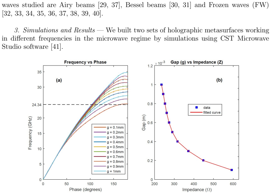
The load-bearing mechanism is the pair of mappings $Z=i[X+M\Phi]$ and $g=g(Z)$. The first converts each hologram pixel's phase $\Phi$ into a surface impedance $Z$, with $X$ and $M$ chosen so the impedance falls inside the range the unit cells can produce. The second is an interpolation curve built from unit-cell simulations: for each gap size, an eigenmode solver gives the phase shift across the cell, and the paper uses the analytic relation $Z=Z_0\sqrt{1-\phi^2 c^2/\omega^2 d^2}$ to turn that phase into impedance. The combination assigns a unique gap size to every CGH pixel, allowing the metasurface to be drawn as an array of metallic patches with variable gaps.
What would settle it
Simulate or measure the radiated field from the complete 128×128 metasurface at 24.34 GHz and compare the transverse intensity profile and longitudinal evolution to the theoretical Bessel (central spot 0.28 mm), Airy (decay parameter 0.1), and Frozen Wave (six superposed Bessel beams, spot 7.8 mm) patterns; if the field does not remain non-diffracting over a substantial propagation distance, the gap-to-phase mapping is not sufficient.
Extended reading notes
Core claim
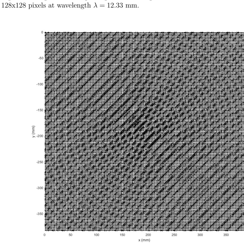
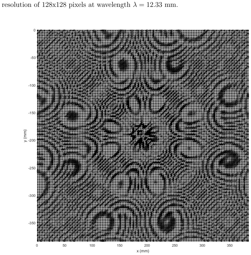
The central claim is that the holographic impedance technique can be translated from the optical regime to microwave metasurfaces by encoding phase information in geometric gap sizes. Each pixel of the CGH is assigned a phase between 0 and 2π; the paper uses the relation $Z=i[X+M\Phi]$ to convert that phase into a surface impedance, with $X$ and $M$ chosen so that $Z$ lies within the impedance interval attainable by the unit-cell library. A fitted curve $g=g(Z)$ then gives a unique gap size for each pixel, and the metasurface is built as a lattice of these unit cells. Two sets of HMS are reported: one at 24.34 GHz on a low-permittivity substrate with lattice constant 3 mm and impedance range 235.05 to 591.39 Ω, and one at 2.4 GHz on a higher-permittivity substrate with lattice constant 15 mm and impedance range 188.6 to 483.4 Ω. For each frequency, the paper presents CGHs and the corresponding gap layouts for a Bessel beam, an Airy beam, and a Frozen Wave, and concludes that the resulting metasurfaces generate the encoded non-diffracting waves.
Load-bearing premise
The method assumes that the phase shift imposed by a unit cell depends only on its gap size, and that the assembled array of cells radiates the wavefront encoded in the hologram exactly as the sum of those independent phase shifts; the paper provides no full-array simulation or measurement to confirm this.
Editorial extensions
If this is right
- If the design mapping is correct, the same pipeline can generate holographic metasurfaces for other non-diffracting wave types, such as Mathieu or parabolic beams, by changing only the CGH phase pattern.
- The two frequency designs show the method can be scaled by choosing substrate, lattice constant, and gap range, suggesting it can be adapted to other microwave or millimeter-wave bands.
- A working HMS would provide planar, low-profile sources of Bessel, Airy, and Frozen Waves, which the paper cites as potentially valuable for telecommunications and bioengineering.
Reading between the lines
- A full-wave simulation of the entire 128×128-unit-cell array would be a direct test of the paper's central claim; the reported evidence stops at isolated unit-cell dispersion curves and final gap maps, so inter-cell coupling and edge truncation remain unexamined.
- The analytic conversion from phase to impedance in Eq. (4) appears inconsistent with the preceding dispersion relation (Eq. 3), which could mean the calibration curve $g(Z)$ does not actually produce the intended phase profile unless a numerical calibration is used instead.
- A near-field scan of a fabricated 2.4 GHz HMS, where the 125 mm wavelength eases measurement tolerances, could verify whether the Bessel central spot, Airy main lobe, and Frozen Wave longitudinal pattern match the predictions.
- Because the phase profile is encoded in gap geometry, the metasurface could be fabricated with standard printed-circuit-board etching once the impedance-to-gap curve is established.
Signed reviews
Editorial analysis
A structured set of objections, weighed in public.
Referee Report
Summary. The manuscript describes a design workflow for holographic metasurfaces (HMS) intended to generate non-diffracting waves (Bessel, Airy, and Frozen Waves) at microwave frequencies. The authors simulate periodic unit cells in CST to obtain dispersion curves relating frequency to phase and gap size, derive a surface impedance interval, map computer-generated hologram (CGH) phase values into surface impedance via Z = i[X+MΦ], and then convert each pixel to a gap value through an interpolation g(Z). They present two designs, at 24.34 GHz and 2.4 GHz, each with CGH images and corresponding 128x128 gap layouts. The conclusions claim that the designed HMS generate and reproduce the CGH non-diffracting waves. However, the manuscript contains no full-wave simulation of any assembled metasurface and no measured or simulated radiated field, so the central claim is never tested.
Significance. If the design actually produced the intended beams, the work would be a useful application of holographic impedance surfaces to generate non-diffracting microwaves, with potential for telecommunications and biomedical applications. The workflow of mapping CGH phase to gap layout is clearly presented, and the use of two frequency bands is a positive feature. However, because the paper stops at unit-cell characterization and layout generation, the claimed capability is not demonstrated. The central result (non-diffracting wave generation) remains an assertion. In addition, an algebraic error in Eq. (4) and an inconsistency between the imaginary target impedance and the real calibration curve cast doubt on the validity of the layout itself. The significance of the paper is therefore contingent on corrections and on an actual device-level validation, neither of which is present.
major comments (4)
- [Section 3 (Simulations and Results), Figs. 2-15] The paper shows only unit-cell dispersion curves, CGH images, and final gap maps; no figure shows the field radiated by an assembled 128x128 metasurface and no quantitative comparison with the target Bessel, Airy, or Frozen Wave amplitude/phase profile is provided. The conclusion that the waves are 'generated and reproduced' is therefore unsupported by the evidence in the manuscript. A full-wave simulation of the complete aperture under the intended illumination, or a measured near-field scan, with comparison to the target profile, is essential to the central claim.
- [Section 1, Eq. (4)] Starting from Eqs. (2)-(3), Z = iZ0(kz/k) and (kz/k)^2 = (φc/(ωd))^2 - 1, the correct relation is Z = iZ0 sqrt((φc/(ωd))^2 - 1), not Z0 sqrt(1 - φ²c²/(ω²d²)). The manuscript drops the imaginary unit and reverses the sign under the square root. Since the impedance interval [Zmin, Zmax] and the calibration g(Z) are built from this expression, the error is load-bearing and must be corrected and the numerical intervals recomputed.
- [Section 1, Eqs. (1), (4), and (5)] The target impedance Z = i[X + MΦ] in Eq. (5) is purely imaginary, while the interval [Zmin, Zmax] obtained from Eq. (4) is treated as real ohmic values and used to define X and M. The paper never explains how an imaginary target impedance is matched to the real-valued g(Z) curve. This inconsistency affects every final layout and needs to be resolved before the design procedure can be considered valid.
- [Section 1, unit-cell period d] At the 24.34 GHz design, d = 3 mm and λ = 12.33 mm give d/λ ≈ 0.24, which is inconsistent with the stated sub-wavelength condition d ≲ λ/10 invoked for effective-medium behavior. The design relies on this approximation, so either the condition must be re-examined with supporting evidence or the effective-medium justification removed.
minor comments (5)
- [Abstract and Section 4] The abstract and conclusions contain grammatical errors such as 'metasurfaces to generation' and 'The results is according to'; these should be corrected.
- [Section 3, Airy beam parameters] The Airy beam decay parameter appears as 'a = 0.1 [?]' without a citation or definition; this placeholder needs to be resolved.
- [Section 1, gray-level to phase mapping] The linear mapping from 256 gray levels to phase 0-2π is described in words, but no explicit equation is given; please provide the mapping used.
- [Figure captions for Figs. 2 and 9] The captions do not explain how the operating frequency and the unique phase-per-gap value are read from the superimposed dispersion curves; a brief explanation would aid reproducibility.
- [Section 1, typo] The phrase 'Eingenmode solver' should read 'Eigenmode solver'.
Circularity Check
No circularity: the CGH-to-metasurface mapping is a constructive design transformation; the absent full-wave validation is a verification gap, not a circular derivation.
full rationale
The claimed derivation chain (CGH phase Phi -> surface impedance Z via Eq. 5 -> gap g via the calibrated g(Z) curve -> metasurface layout) is a constructive mapping, not a prediction that reduces to its own inputs. X and M are explicitly adjustment constants chosen to keep Z inside the unit-cell impedance interval, and g(Z) is a calibration curve obtained from unit-cell simulations; these are legitimate holographic-impedance design steps, and they do not secretly define the target radiated field. The paper's central weakness is that it stops at unit-cell dispersion curves and final gap-layout images: no full-wave simulation of the assembled 128x128 aperture and no measured field pattern are shown, so the assertion that Bessel, Airy, and Frozen-Wave fields are 'generated and reproduced' is unverified. However, that is a missing-validation/completeness issue, not a circular reduction: the physical radiated field is never derived, fitted, or equated to an input by construction. The only self-citation, Ref. [41], concerns the unit-cell geometry and is not load-bearing; the impedance formalism itself is attributed to external references [24,25]. Therefore the paper contains no significant circularity.
Assumptions & free parameters
free parameters (5)
- Operating frequency f =
24.34 GHz and 2.4 GHz
- Surface impedance modulation factors X and M =
X = Zmin (235.05 Ω, 188.6 Ω); M = floor((Zmax-Zmin)/(2π)) (56, 46)
- Gap range [gmin, gmax] =
[1, 2.8] mm and [1, 5] mm
- Lattice constant d =
3 mm and 15 mm
- Beam parameters (kρ, a, N, Q) =
kρ = 16 mm^-1, a = 0.1, N = 6, Q = 407.67 and 4.52
assumptions (4)
- domain assumption Effective medium theory is valid when d ≲ λ/10
- standard math The holographic surface impedance relation Z = i[X + M Re(ψ_rad ψ_surf*)] (Eq. 1) correctly encodes the desired radiation pattern
- domain assumption TM surface-wave dispersion relation holds on the designed unit cell
- domain assumption CST Microwave Studio eigensolver accurately models the unit cells
Cite this review
Pith. "Pith review of Holographic metasurfaces simulations applied to realization of non-diffracting waves in the microwave regime." pith.science (2026). https://pith.science/paper/OMQF6KQQ
@misc{pith2026190809624,
  author       = {Pith},
  title        = {Pith review of: Holographic metasurfaces simulations applied to realization of non-diffracting waves in the microwave regime},
  year         = {2026},
  howpublished = {\url{https://pith.science/paper/OMQF6KQQ}},
  note         = {Machine review of arXiv:1908.09624}
}
read the original abstract
In this work, we present the computational realization of holographic metasurfaces to generation of the non-diffracting waves. These holographic metasurfaces (HMS) are simulated by modeling a periodic lattice of metallic patches on dielectric substrates with sub-wavelength dimensions, where each one of those unit cells alter the phase of the incoming wave. We use the surface impedance (Z) to control the phase of the electromagnetic wave through the metasurface in each unit cell. The sub-wavelength dimensions guarantees that the effective medium theory is fulfilled. The metasurfaces are designed by the holographic technique and the computer-generated holograms (CGHs) of non-diffracting waves are generated and reproduced using such HMS in the microwave regime. The results is according to the theoretically predicted by non-diffracting wave theory. These results are important given the possibilities of applications of these types of electromagnetic waves in several areas of telecommunications and bioengineering.
Figures


Figures from the paper (12 more)




Reference graph
Works this paper leans on
-
[1]
Photonic Crystals. Molding the flow of light
J. Joannopoulos, S. Johnson, J. Winn, R. Meade. “Photonic Crystals. Molding the flow of light”. Princeton University Press, second edition, 2008
work page 2008
-
[2]
E. Yablonovitch. “Photonic band-gap crystals”. Journal of Physics Condensed Matter 5, 2443 (1993)
work page 1993
-
[3]
The Electrodynamics of Substances with simultaneously negative val- ues of ε and µ
V. Veselago. “The Electrodynamics of Substances with simultaneously negative val- ues of ε and µ”. Soviet Physics Uspekhi 10, 4 (1968)
work page 1968
-
[4]
Metamaterials: a new frontier of science and technology
Y. Liu, X. Zhang. “Metamaterials: a new frontier of science and technology”. Chem- ical Society Reviews 40, 2494-2507 (2011)
work page 2011
-
[5]
Physics of negative refractive index materials
S. Ramakrishna. “Physics of negative refractive index materials”. Reports on Progress in Physics 68, 449-521 (2005). 13
work page 2005
- [6]
-
[7]
Composite Medium with Simultaneously Negative Permeability and Permittivity
D. Smith et al. “Composite Medium with Simultaneously Negative Permeability and Permittivity”. Physics Review Letters. 84, 4184 (2000)
work page 2000
-
[8]
Negative Refractive Index in Left-Handed Materials
D. Smith, N. Kroll. “Negative Refractive Index in Left-Handed Materials”. Physical Review Letters. 85, 2933 (2000)
work page 2000
Show all 41 references
-
[9]
Negative Refraction Makes a Perfect Lens
J. Pendry. “Negative Refraction Makes a Perfect Lens”. Physical Reviews Letters 85, 3966 (2000)
2000
-
[10]
Superlenses to overcome the diffration limit
X. Zhang, Z. Liu. “Superlenses to overcome the diffration limit”. Nature materials 7, 435 (2008)
2008
-
[11]
Metamaterials and Negative Refractive Index
D. Smith et al . “Metamaterials and Negative Refractive Index”. Science 305, 788 (2004)
2004
-
[12]
Experimental Verification of a Negative Index of Refraction
R. Shelby et al. “Experimental Verification of a Negative Index of Refraction.” Science 292, 77 (2001)
2001
-
[13]
Negative Refraction at Visible Frequencies
H. Lezec, J. Dionne, H. Atwater. “Negative Refraction at Visible Frequencies.” Sci- ence 316, 430 (2007)
2007
-
[14]
Controlling Electromagnetic Fields
J. Pendry et al. “Controlling Electromagnetic Fields”. Science 312, 1780 (2006)
2006
-
[15]
Metamaterial Electromagnetic Cloak at Microwave Frequencies
D. Schuring et al. “Metamaterial Electromagnetic Cloak at Microwave Frequencies”. Science 314, 977 (2006)
2006
-
[16]
A discussion on the interpretation and characterization of metafilms/metasurfaces: The two-dimensional equivalent of metamaterials
C. Holloway et al . “A discussion on the interpretation and characterization of metafilms/metasurfaces: The two-dimensional equivalent of metamaterials”. Meta- materials 3, 100-112 (2009)
2009
-
[17]
A review of metasurfaces: physics and applications
H. Chen, A. Taylor, N. Yu. “A review of metasurfaces: physics and applications”. Reports on Progress in Physics 79, 076401 (2016)
2016
-
[18]
Light propagation with phase discontinuities: generalized laws of re- flection and refraction
N. Yu et al . “Light propagation with phase discontinuities: generalized laws of re- flection and refraction”. Science 334, 333 (2011)
2011
-
[19]
Reflection and refraction of light from metasurfaces with phase dis- continuities
F. Aieta et al. “Reflection and refraction of light from metasurfaces with phase dis- continuities”. Journal of Nanophotonics 6, 063532 (2012)
2012
-
[20]
Planar Photonics with Metasurfaces
A. Kildishev, A. Boltasseva, V. Shalaev. “Planar Photonics with Metasurfaces”. Sci- ence 339, 1232009 (2013)
2013
-
[21]
Broadband Metasurfaces with Simultaneous Control of Phase and Amplitude
L. Liu et al . “Broadband Metasurfaces with Simultaneous Control of Phase and Amplitude”. Advanced Materials Banner 26, 5031 (2014)
2014
-
[22]
Giant birefringence in optical antenna arrays with widely tailorable optical anisotropy
M. Kats et al. “Giant birefringence in optical antenna arrays with widely tailorable optical anisotropy”. Proceedings of the National Academy of Sciences of USA 109, 12364 (2012). 14
2012
-
[23]
Plasmonic holographic imaging with V-shaped nanoan- tenna array
F. Zhou, Y. Liu, W. Cai. “Plasmonic holographic imaging with V-shaped nanoan- tenna array”. Optics Express 21, 4348 (2013)
2013
-
[24]
Scalar and Tensor Holographic Artificial Impedance Surfaces
B. Fong et al. “Scalar and Tensor Holographic Artificial Impedance Surfaces”. IEEE Transactions on Antennas and Propagation 58, 3212 (2010)
2010
-
[25]
Frequency-Controls of Electromagnetic Multi-Beam Scanning by Metasurfaces
Y. Li, X. Wan, B. Cai et al . “Frequency-Controls of Electromagnetic Multi-Beam Scanning by Metasurfaces”. Scientific Reports 4, 6921 (2014)
2014
-
[26]
Fundamentals of Photonics
B. Saleh, M. Teich. “Fundamentals of Photonics”. John Wiley & Sons, INC (1991)
1991
-
[27]
Introduction to Fourier Optics
J. Goodman. “Introduction to Fourier Optics”. Roberts & Co. Publishers, 2 ed. (2004)
2004
-
[28]
Optical Holography
P. Hariharan. “Optical Holography”. Cambridge University Press, 2 ed. (1996)
1996
-
[29]
Accelerating finite energy Airy beams
G. Siviloglou and D. Christodoulides. “Accelerating finite energy Airy beams”. Optics Letters 32, 979 (2007)
2007
-
[30]
Generation of nondiffracting Bessel beams by use of a spatial light modulator
N. Chattrapiban et al. “Generation of nondiffracting Bessel beams by use of a spatial light modulator”. Optics Letters 28, 2183 (2003)
2003
-
[31]
Comparison of Bessel and Gaussian beams
J. Durnin, J. Miceli and J. Eberly. “Comparison of Bessel and Gaussian beams”. Optics Letters 13, 79 (1988)
1988
-
[32]
Stationary optical wave fields with arbitrary longitudinal shape by superposing equal frequency Bessel beams: Frozen Waves
M. Zamboni-Rached. “Stationary optical wave fields with arbitrary longitudinal shape by superposing equal frequency Bessel beams: Frozen Waves”. Optics Express 12, 4002 (2004)
2004
-
[33]
Frozen waves: experimental generation
T. A. Vieira, M. R. R. Gesualdi, M. Zamboni-Rached. “Frozen waves: experimental generation”. Optics Letters 37, 2034 (2012)
2012
-
[34]
Modeling the spatial shape of nondiffracting beams: Experimental generation of Frozen Waves via holographic method
T. A. Vieira, M. Zamboni-Rached, M. R. R. Gesualdi. “Modeling the spatial shape of nondiffracting beams: Experimental generation of Frozen Waves via holographic method”. Optics Communications 315, 374 (2014)
2014
-
[35]
Production of dynamic frozen waves: controlling shape, location (and speed) of diffraction-resistant beams
T. A. Vieira, M. R. R. Gesualdi, M. Zamboni-Rached and E. Recami. “Production of dynamic frozen waves: controlling shape, location (and speed) of diffraction-resistant beams”. Optics Letters 40, 5834 (2015)
2015
-
[36]
Architecting new diffraction-resistant light structures and their possible applications in atom guidance
E. G. P. Pachon, M. Zamboni-Rached, A. Dorrah, M. Mojahedi, M. R. R. Gesualdi and G. G. Cabrera. “Architecting new diffraction-resistant light structures and their possible applications in atom guidance”. Optics Express 24, 25403 (2016)
2016
-
[37]
Photorefractive and computational holography in the experimental generation of Airy beams
R. A. B. Suarez, T. A. Vieira, I. S. V. Yepes, M. R. R. Gesualdi. “Photorefractive and computational holography in the experimental generation of Airy beams”. Optics Communications 366, 291 (2016)
2016
-
[38]
Optical reconstruction of non-diffracting beams via photorefractive holography
T. A. Vieira, R. A. B. Suarez, I. S. V. Yepes, M. R. R. Gesualdi, M. Zamboni-Rached. “Optical reconstruction of non-diffracting beams via photorefractive holography”. Applied Physics. B, Lasers and Optics 123, 134 (2017). 15
2017
-
[39]
Structured Light by Linking Diffraction-Resistant Spatially Shaped Beams
M. Zamboni-Rached, E. Recami, T. A. Vieira, M. R. R. Gesualdi, J. Nobre-Pereira. “Structured Light by Linking Diffraction-Resistant Spatially Shaped Beams”. Phys- ical Review Applied 10, 034023 (2018)
2018
-
[40]
T. A. Vieira, M. Zamboni-Rached, M. R. R. Gesualdi. “Experimental Generation of Frozen Waves in Optics: Control of Longitudinal and Transverse Shape of Optical Non-diffracting Waves. In: H. E. Hern ˜A¡ndez-Figueroa, E. Recami and M. Zamboni- Rached. (Org.). Non-Diffracting Waves...
2013
-
[41]
Holographic metasurfaces applied to gen- eration of non-diffracting beams
S. R. C. Fernandez, M. R. R. Gesualdi. “Holographic metasurfaces applied to gen- eration of non-diffracting beams”. Latin America Optics and Photonics Conference. Washington: OSA Th4A.22 (2018). 16
2018
Reviewed August 14, 2026 · model on record in the stance chip above.
Discussion (0). Continue with ORCID to comment.