On-sky Fibre-Target-Alignment of the 4MOST instrument: calibration and performance
Pith reviewed 2026-06-29 03:12 UTC · model grok-4.3
The pith
4MOST fibre positioner reaches 16 micrometre RMS alignment to sky targets after calibration.
A machine-rendered reading of the paper's core claim, the machinery that carries it, and where it could break.
Core claim
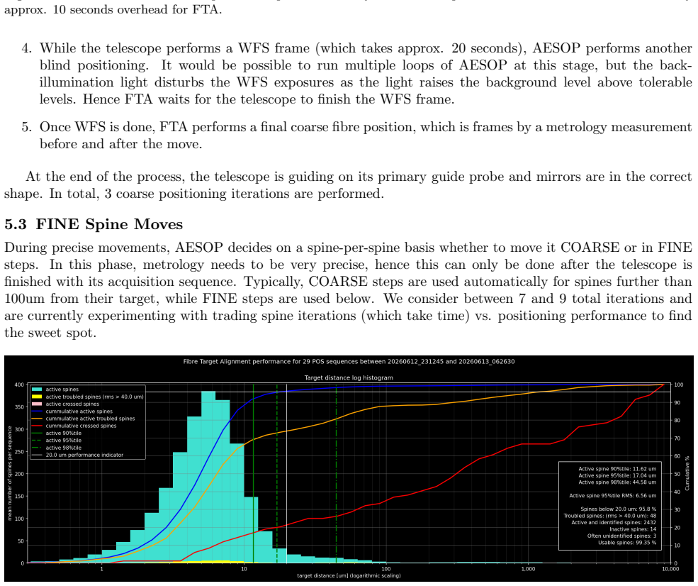
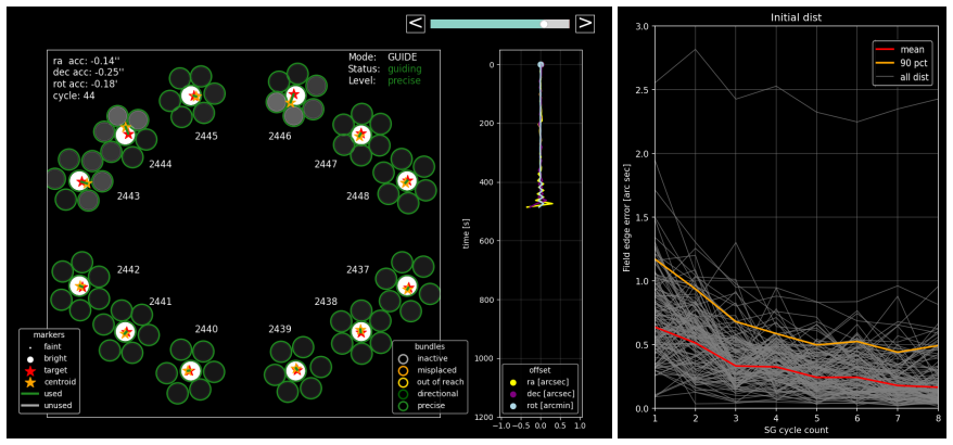
By calibrating the metrology camera system, the AESOP fibre positioner, the spine-based secondary guiding system, the sky-to-focal-surface projection software, and applying residual minimization via raster scans against a large calibration target, the 4MOST instrument attains an on-sky fibre-target alignment of approximately 16 micrometres RMS (0.27 arcseconds) six months after final hardware installation.
What carries the argument
The metrology camera system together with the large calibration target, used as the stable reference for focal-surface geometry and combined with raster-scan residual minimization.
If this is right
- The achieved alignment far exceeds the stated accuracy requirements of the instrument.
- Trade-off studies can now prioritize scientific return rather than basic positional performance.
- The calibration process required only one month of accumulated telescope time after hardware installation.
- The system supports simultaneous spectroscopy of 2436 targets over a 4.2 square degree field at the reported precision.
Where Pith is reading between the lines
- Comparable calibration sequences could be adopted by other fibre-fed multi-object spectrographs to reach similar on-sky accuracy.
- The improvement observed between first light and six months later indicates that continued software or stability refinements remain possible.
- High positional accuracy may allow the use of smaller fibre diameters, which would increase spectral resolution without loss of throughput.
Load-bearing premise
The metrology camera system and large calibration target provide an accurate, stable reference for the focal surface geometry without unaccounted systematic distortions.
What would settle it
Direct on-sky measurements of fibre positions against known stellar targets that show RMS errors remaining above 24 micrometres or reveal systematic offsets not captured by the calibration model.
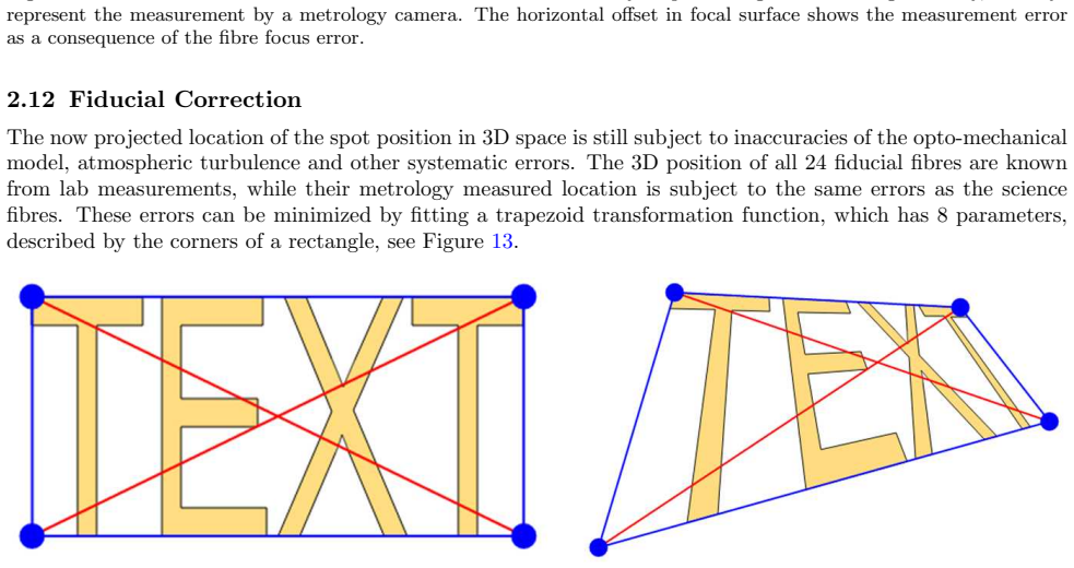
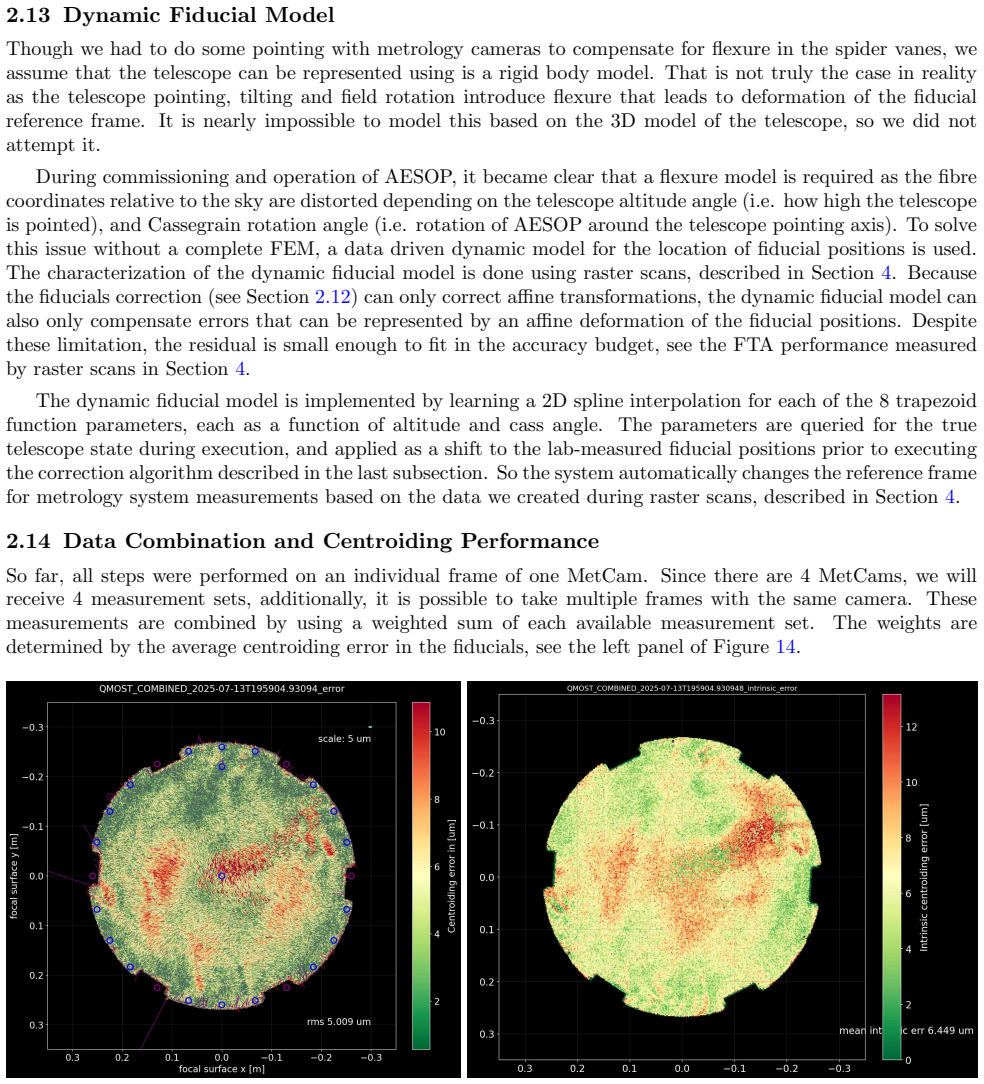
Figures
read the original abstract
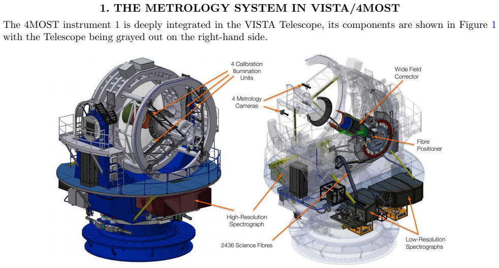
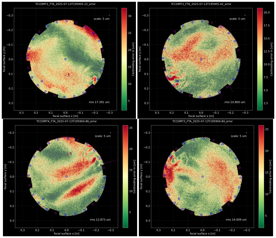
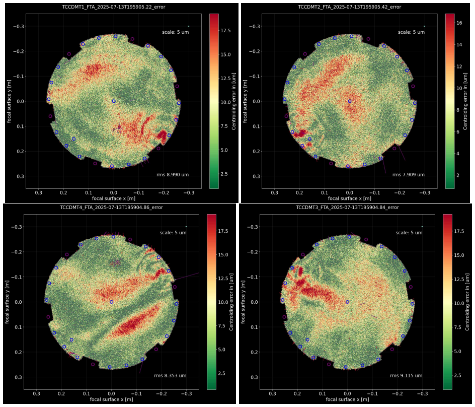
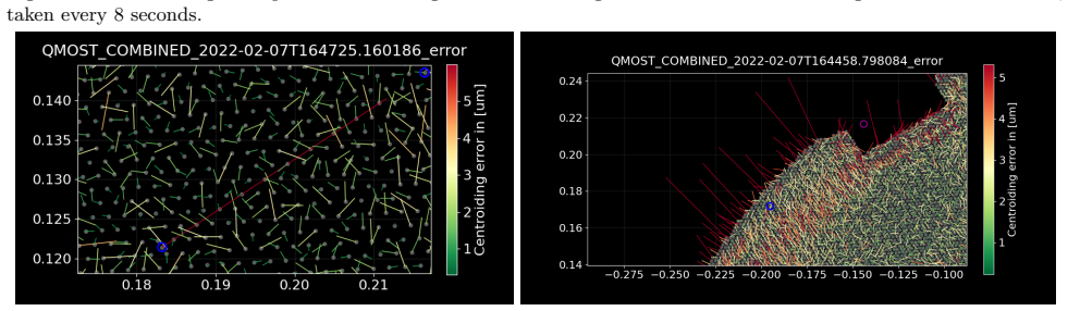
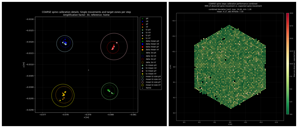
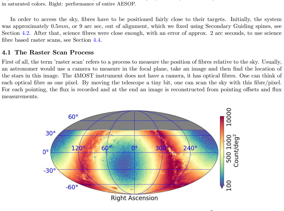
The 4-metre Multi-Object Spectroscopic Telescope (4MOST) is a new wide-field, fibre-fed spectroscopic survey facility for the VISTA telescope at ESOs Paranal Observatory. The instrument enables the simultaneous acquisition of 2436 spectra across a 4.2 square deg field of view, using a tilting spine fibre positioner feeding three dedicated spectrographs. In this paper, we describe the calibration process, and performance verification of the Fibre-Target-Alignment (FTA) process for 4MOST. We show the complete FTA process, including calibration of the individual hardware- and software components. Namely the Metrology camera system, the Fibre Positioner AESOP, a spine based Secondary Guiding System, the sky to focal surface projection software, and residual minimization via raster scans. In total, the FTA system required one special tool, a large calibration target for the focal surface, and approximately 1 month of accumulated calibration work on the telescope. The FTA process reached approx. 24 um (0.4 arc sec) RMS distance between fibres and targets on sky about 3 weeks after installation of the final hardware components of 4MOST, which is when 4MOST had its first light event. By the time of writing this paper, i.e. 6 months later, we reach approx. 16 um (0.27 arc sec) RMS. Currently, we far exceed our requirements in terms of accuracy, and are doing trade-off studies to maximize scientific returns.
Editorial analysis
A structured set of objections, weighed in public.
Referee Report
Summary. The manuscript describes the calibration process and on-sky performance verification of the Fibre-Target-Alignment (FTA) system for the 4MOST instrument. It covers calibration of the metrology camera system, AESOP fibre positioner, spine-based secondary guiding system, sky-to-focal-surface projection software, and residual minimization via raster scans using a large calibration target. The FTA process achieved ~24 μm (0.4 arcsec) RMS alignment ~3 weeks after final hardware installation (first light) and improved to ~16 μm (0.27 arcsec) RMS after six months, exceeding requirements.
Significance. If the reported on-sky RMS values hold, the work demonstrates that the FTA system achieves high-precision fibre positioning for a 2436-fibre wide-field spectrograph, directly enabling the scientific goals of the 4MOST survey. The detailed timeline of calibration steps and the observed improvement provide a practical reference for similar fibre positioner systems. The use of on-sky measurements after hardware installation strengthens the performance claims.
major comments (2)
- [Metrology camera system calibration] Metrology camera system and large calibration target sections: the headline 16 μm RMS on-sky claim is obtained by minimizing residuals referenced to this system. The manuscript describes internal calibration steps but provides no independent external cross-check (e.g., direct comparison to stellar positions from another instrument or repeated observations with an external metrology method). This assumption is load-bearing for the central performance result.
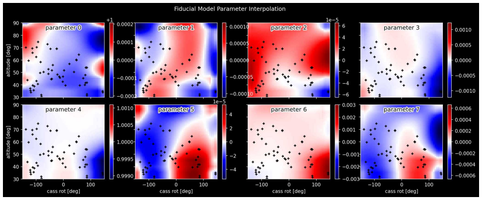
- [Sky-to-focal-surface projection software] Sky-to-focal-surface projection software section: the projection involves free parameters that are tuned during calibration and raster scans. The manuscript does not quantify how uncertainties or potential systematics in these parameters (or in the metrology reference) propagate into the final RMS values, which is needed to assess robustness of the 16 μm result.
minor comments (2)
- [Abstract] Abstract and performance results: the RMS values at the two epochs are stated without associated uncertainties, number of fibres/targets sampled, or details on the distribution of residuals; adding these would improve clarity and allow readers to assess the measurements.
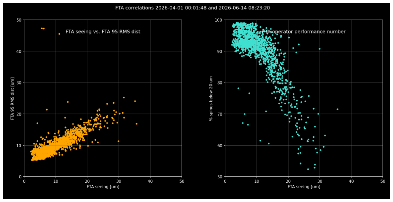
- [Calibration process] The description of the one-month calibration effort and subsequent six-month improvement would benefit from a table or timeline figure summarizing the sequence of hardware/software steps and the corresponding RMS measurements.
Simulated Author's Rebuttal
We thank the referee for their careful reading and constructive feedback on our manuscript. We address each of the major comments below.
read point-by-point responses
-
Referee: Metrology camera system and large calibration target sections: the headline 16 μm RMS on-sky claim is obtained by minimizing residuals referenced to this system. The manuscript describes internal calibration steps but provides no independent external cross-check (e.g., direct comparison to stellar positions from another instrument or repeated observations with an external metrology method). This assumption is load-bearing for the central performance result.
Authors: We note that the 16 μm RMS is measured using the metrology camera system as the reference after its calibration with the large calibration target. The manuscript details the internal calibration procedures, including multiple raster scans to minimize residuals. An independent external cross-check was not available during the commissioning period. However, the progressive improvement in alignment accuracy over six months and the system's ability to meet and exceed the survey requirements serve as practical validation of the performance. We have revised the text to emphasize that the quoted RMS is with respect to the calibrated metrology reference system. revision: partial
-
Referee: Sky-to-focal-surface projection software section: the projection involves free parameters that are tuned during calibration and raster scans. The manuscript does not quantify how uncertainties or potential systematics in these parameters (or in the metrology reference) propagate into the final RMS values, which is needed to assess robustness of the 16 μm result.
Authors: The manuscript does not include a formal error propagation analysis for the free parameters in the sky-to-focal-surface projection software. We agree this would help assess the robustness. In the revised version, we will add a quantitative discussion of how uncertainties in these parameters, derived from the calibration data, affect the final RMS value. revision: yes
Circularity Check
No circularity: on-sky RMS is direct empirical measurement after calibration
full rationale
The paper reports hardware calibration steps followed by direct on-sky measurements of fibre-target residuals (reaching 16 µm RMS). No equations, fitted parameters, or self-citations are used to derive the headline performance number; the RMS is obtained from actual sky observations referenced to the installed system. The metrology camera and calibration target are inputs to the alignment process, but the final reported accuracy is an independent observational outcome, not a quantity defined by or forced to equal those inputs. This matches the default case of a self-contained empirical result.
Axiom & Free-Parameter Ledger
free parameters (1)
- sky-to-focal-surface projection parameters
axioms (1)
- domain assumption Metrology camera measurements accurately represent the true positions of fibre tips on the focal surface.
Reference graph
Works this paper leans on
-
[1]
4MOST: the 4-metre Multi-Object Spectroscopic Telescope Project at the start of commissioning,
de Jong, R. S., Bellido-Tirado, O., Brynnel, J. G., Amini, A. E., Frey, S., F¨ ußlein, C., Giannone, D., Johl, D., Kuba, S., Lemke, U., Micheva, G., Saviauk, A., Steinmetz, M., Walcher, J. C., Winkler, R., Lind, K., Loveday, J., Mainieri, V., Pirard, J.-F., Gaessler, W., Laurent, F., Merloni, A., Navarro, R., Remillieux, A., Rothmaier, F., Smedley, S., an...
2024
-
[2]
Overall performance of AESOP: the 4MOST fibre positioner,
Brzeski, J., Adams, D., Baker, G., Baker, S., Brown, R., Case, S., Chin, T., Coyne, J., Farrell, T., Gilling- ham, P., Houston, E., Klauser, U., Kripak, Y., Kunwar, N., Lawrence, J., Mali, S., Maslak, W., McGregor, H., Muller, R., Nichani, V., Pai, N., O’brien, E., Saunders, W., Smedley, S., Venkatesan, S., Waller, L., Zahoor, J., and Zheng, J., “Overall ...
2022
-
[3]
Crescent moons: an update on the ongoing construction of the new vlt’s multi-object spectrograph,
Cirasuolo, M., Gonzalez, O., Rees, P., Bryson, I., Fairley, A., Taylor, W., Afonso, J., Lilly, S., Evans, C., Flores, H., et al., “Crescent moons: an update on the ongoing construction of the new vlt’s multi-object spectrograph,” in [Ground-based and Airborne Instrumentation for Astronomy VIII],11447, 222–232, SPIE (2020)
2020
-
[4]
The assembly and alignment of the 4most wide field corrector,
Cunningham, M. H., Doel, P., Brooks, D., Brynnel, J., Frey, S., deJong, R., G¨ abler, M., Schr¨ ock, M., Lehmitz, M., Sablowski, D., and Barden, S., “The assembly and alignment of the 4most wide field corrector,” in [Proc. SPIE],12184, Paper 257 (2022)
2022
-
[5]
4MOST Metrology System Optical and Mechanical Design,
Barden, S. C., Saviauk, A., and Winkler, R., “4MOST Metrology System Optical and Mechanical Design,” Proc. SPIE9908, 331 (2016)
2016
-
[6]
4most fibre feed: performance and final design,
Haynes, D. M., Saviauk, A., Kelz, A., Jahn, T., Haynes, R., Pl¨ uschke, D., Zscheyge, F., Brown, R., Pi- otrowski, J., Winkler, R., and Barden, S., “4most fibre feed: performance and final design,”Proc. SPIE 10702(2018)
2018
-
[7]
The fibre target alignment process of the 4MOST instrument,
Winkler, R., Stilz, I., Pramskiy, A., Sun, W., Roje, P., Liebner, T., Sablowski, D., Frey, S., Zins, G., and Smedley, S., “The fibre target alignment process of the 4MOST instrument,” in [Software and Cyberinfras- tructure for Astronomy VIII], Ibsen, J. and Chiozzi, G., eds.,13101, 131010L, International Society for Optics and Photonics, SPIE (2024)
2024
-
[8]
The 4MOST facility control software,
Mandel, H. G., Pramskiy, A., Rothmaier, F. M., Stilz, I., and Winkler, R., “The 4MOST facility control software,” in [Software and Cyberinfrastructure for Astronomy IV],9913, 991336, International Society for Optics and Photonics (2016)
2016
-
[9]
On implementing 2d rectangular assignment algorithms,
Crouse, D. F., “On implementing 2d rectangular assignment algorithms,”IEEE Transactions on Aerospace and Electronic Systems52(4), 1679–1696 (2016)
2016
-
[10]
The astropy project: Sustaining and growing a community-oriented open-source project and the latest major release (v5.0) of the core package,
Astropy Collaboration and Astropy Project Contributors, “The astropy project: Sustaining and growing a community-oriented open-source project and the latest major release (v5.0) of the core package,”apj935, 167 (Aug. 2022)
2022
-
[11]
Probabilistic fibre-to-target assignment algorithm for multi-object spectroscopic surveys,
Tempel, E., Norberg, P., Tuvikene, T., Bensby, T., Chiappini, C., Christlieb, N., Cioni, M.-R. L., Comparat, J., Davies, L. J. M., Guiglion, G., Koch, A., Kordopatis, G., Krumpe, M., Loveday, J., Merloni, A., Micheva, G., Minchev, I., Roukema, B. F., Sorce, J. G., Starkenburg, E., Storm, J., Swann, E., Thi, W. F., Traven, G., and de Jong, R. S., “Probabil...
2020
discussion (0)
Sign in with ORCID, Apple, or X to comment. Anyone can read and Pith papers without signing in.