REVIEW 4 major objections 4 minor 39 references
Reentrant Pinning, Dynamic Row Reduction, and Skyrmion Accumulation for Driven Skyrmions in Inhomogeneous Pinning Arrays
T0 review · 4 major / 4 minor · reviewed 2026-08-14 · deepseek-v4-flash
Pith's one-line read Under drive, skyrmions in a half-pinned sample accumulate against the pinned stripe, shed flowing rows in discrete steps, and at low filling or strong pinning freeze into a reentrant pinned state.
desk verdict Solid particle-based skyrmion study with a plausible row-reduction mechanism, but the reentrant-pinning phase needs a hysteresis check before I'd trust it. read the letter →
The pith
A machine-rendered reading of the paper's core claim, the machinery that carries it, and where it could break.
The reading
What carries the argument
The machinery is the particle-based Thiele equation $\alpha_d \mathbf{v}_i + \alpha_m \hat{z} \times \mathbf{v}_i = \mathbf{F}^{ss}_i + \mathbf{F}^D$, with a constant Magnus coefficient $\alpha_m$ and a truncated Bessel repulsion between skyrmions, together with parabolic pinning traps. The Magnus term gives a fixed intrinsic Hall angle $\theta^{\mathrm{int}}_{\mathrm{sk}} = \arctan(\alpha_m/\alpha_d)$, and it is this transverse push that compresses the flowing skyrmions against the pinned stripe and eventually steers them into the pinning sites. The mechanism that carries the argument is the coupling between drive, Hall angle, and row number: as the drive $F_D$ rises, the transverse Magnus push grows, the number of integer rows $N_r$ in the unpinned channel drops in steps, and each step coincides with a velocity drop in $\langle V_\parallel \rangle$.
What would settle it
In a sample patterned with a half-pinned stripe, measure $\langle V_\parallel \rangle$ as a function of drive at low filling and strong pinning; if there is no finite interval of drive over which the average velocity is exactly zero while nearby drives flow, the reentrant pinning claim is wrong. Similarly, the staircase of negative differential conductivity would be refuted if the velocity curve is monotonic for a large intrinsic Hall angle.
Extended reading notes
Core claim
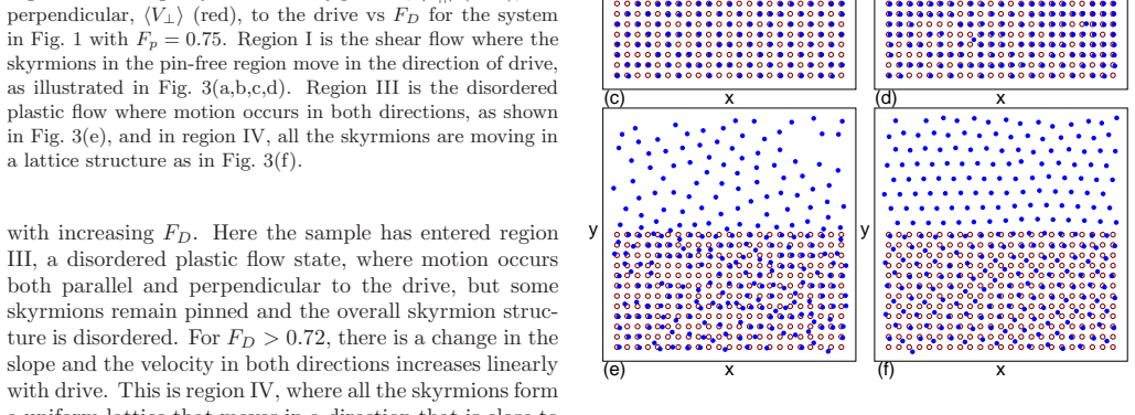
The central claim is that a skyrmion lattice driven parallel to a stripe of strong pinning, with a coexisting pin-free region, undergoes a series of dynamical structural transitions driven by the skyrmion Hall effect. Initially only the unpinned skyrmions move, guided parallel to the drive by the barrier of pinned skyrmions, and the velocity–force curve shows a staircase of sharp drops. Each drop corresponds to a reduction in the number of flowing skyrmion rows, as groups of skyrmions are pushed into the pinned region by the Magnus force and the remaining flowing lattice rearranges to preserve an integer row count. When the number of pinning sites is large relative to the skyrmion number, or the pinning is strong, a reentrant pinning phase appears in which the Hall drift forces all skyrmions to enter the pinned region and the average velocity is exactly zero over a finite drive interval; this window widens with increasing intrinsic skyrmion Hall angle and disappears in the overdamped limit.
Load-bearing premise
The load-bearing premise is that treating each skyrmion as a rigid particle with a fixed sideways-drift coefficient reproduces real skyrmion behaviour; if real skyrmions deform, change their Hall angle with drive, or escape at sample edges, the predicted phase boundaries could shift or the reentrant zero-velocity window could disappear.
Editorial extensions
If this is right
- In any skyrmion system with inhomogeneous pinning, the velocity–force curve should show a staircase of drops with negative differential conductivity as rows of flowing skyrmions are lost to the pinned region.
- At low filling or with strong pinning, a finite drive window should exist in which all skyrmions are trapped in the pinned region, giving exactly zero average velocity; this reentrant pinning window widens as the intrinsic skyrmion Hall angle increases.
- In the overdamped limit where the Magnus term is negligible, both the row-reduction staircase and the reentrant pinning phase disappear, leaving monotonic flow.
- At high drive the system reorders into a uniform moving lattice whose Hall angle approaches the intrinsic angle, so the pinned stripe no longer guides the motion.
- Drive-induced skyrmion accumulation and density gradients along the edge of the pinned region should be observable as a general consequence of the Hall effect, not just in the idealized stripe geometry.
Reading between the lines
- A current-driven experiment on a half-pinned skyrmion sample should show a zero-velocity plateau in the differential resistance that widens with the intrinsic Hall angle; observing that plateau would confirm the mechanism, and its absence for strong pinning would contradict it.
- The row-reduction staircase provides a way to count the number of flowing rows in situ: each velocity step marks the loss of one row, so the steps themselves are a direct readout of the internal channel structure.
- The same accumulation mechanism should appear in other systems with a transverse Magnus-like force, such as driven colloids or active particles in a confining channel, where an analogous density gradient and stepwise row loss could be tested without magnetic materials.
- For device design, a drive pulse could be used to deliberately trap a skyrmion population in the pinned region, and a second stronger pulse could release it; the phase diagram suggests the required pulse amplitudes.
Signed reviews
Editorial analysis
A structured set of objections, weighed in public.
Referee Report
Summary. The manuscript studies a two-dimensional particle-based model of skyrmions described by the Thiele equation (Eq. 1) with damping, Magnus force, Bessel repulsion, and parabolic pinning sites occupying only half of the sample. The authors apply a drive along the pinned stripe and record the parallel and perpendicular average velocities as functions of drive strength. They identify four dynamical phases: shear flow confined to the unpinned region with zero transverse velocity and stepwise row reduction, reentrant pinning with zero velocity over a finite drive window, disordered plastic flow, and a uniformly moving lattice. Phase diagrams are constructed as functions of filling fraction, Magnus coefficient, and pinning strength. The central claims are that drive alone produces row-reduction events with negative differential conductivity and that sufficiently strong pinning or low filling produces a reentrant pinning phase caused by the skyrmion Hall effect pushing all skyrmions into the pinned stripe.
Significance. The qualitative phenomena are plausible and potentially useful for skyrmion device concepts: inhomogeneous pinning can guide skyrmion flow, produce density gradients, and, if the reentrant pinning is robust, allow drive-controlled trapping. Strengths of the manuscript are that the results are generated from standard equations without data fitting, the row-count snapshots in Fig. 3 are consistent with the velocity steps in Fig. 2, and the claimed dependence on the Magnus term is directly tested in Fig. 4(b). The main risks are that the reentrant phase is identified with a single upward T=0 drive sweep, and that the phase diagrams lack explicit system-size and phase-boundary criteria.
major comments (4)
- [Simulation and Fig. 4(a)] The zero-velocity interval defining phase II is obtained by increasing F_D from the annealed T=0 state in small increments, with no downward sweep, no random initial configurations, and no basin-of-attraction analysis. At T=0, Eq. (1) is deterministic, so any configuration whose total force is below the pinning threshold remains trapped regardless of whether a flowing steady state also exists. The reentrant-pinning boundary in Figs. 5 and 6 may therefore be a property of the quasi-static ramp protocol rather than a robust phase. Please add downward sweeps and multiple random initial conditions, and report whether the zero-velocity window persists.
- [Simulation and Figs. 2, 3, 5, 6] The manuscript never reports the system size, number of skyrmions N_s, number of pins N_p, or the transverse width of the sample; only ratios N_s/N_p are given. The number of flowing rows in Fig. 3 and the step positions in Fig. 2 depend directly on the channel width, so the phase boundaries in Figs. 5(a), 5(b), and 6(b) may be system-size dependent. Please state the system dimensions and add finite-size tests, such as doubling the width at fixed filling and pinning strength, to show that the qualitative phase diagram is unchanged.
- [Fig. 5(a) and text on reentrant phase range] The text states "For N_s/N_p < 0.5 we observe a new reentrant phase" (Fig. 4(a)) but later states "Phase II appears only for N_s/N_p < 0.1" for the same F_D versus N_s/N_p diagram. These statements are mutually inconsistent, and Fig. 6(a) shows phase II at N_s/N_p = 1.0 for F_p > 2.0. Please reconcile the phase diagram and the text, and specify the exact range of filling for which phase II appears at fixed F_p.
- [Figs. 5 and 6] The phase-boundary determination is not described. The text names regions I-IV but does not give quantitative criteria, such as thresholds for <V_perp>, <V_parallel>, or structural order parameters, used to draw the boundaries in Figs. 5 and 6. Without these criteria or representative error estimates, the phase diagrams cannot be reproduced or compared with future experiments. Please define the protocol and criteria explicitly.
minor comments (4)
- [Throughout] Several typographical errors need correction: "discuses" in the Introduction, "in the of absence pinning" in the Simulation section, "N_s/N_v" in the Fig. 4(b) caption, "digram" in the Fig. 6(b) caption, and the title line contains "Acc u- mulation".
- [Simulation] The simulation section should specify the truncation distance and normalization of the Bessel interaction K_1(r), and the pinning potential should be written explicitly as a function of position rather than only described as parabolic traps of radius r_p = 0.25 with maximum strength F_p.
- [Figure captions] The caption of Fig. 5(a) does not state the fixed pinning strength; the reader must infer F_p = 0.75 from the main text. Please state all parameters consistently in each figure caption.
- [Summary and discussion] The manuscript does not discuss how thermal fluctuations or skyrmion deformation would affect the reentrant pinning and row reduction; one sentence acknowledging these model limitations would help calibrate the claim that the effects are general features of skyrmion systems.
Circularity Check
No circularity: row reduction and reentrant pinning are emergent outputs of a forward Thiele-equation simulation with no fitted predictions.
full rationale
The paper reports direct particle-based simulations of skyrmion motion using an explicitly stated equation of motion (Eq. 1) with fixed parameters, and all reported quantities—velocity-force curves, row numbers, phase boundaries, and the reentrant pinning interval—are measured simulation outputs rather than inputs. No parameter is fitted to the target data, and no 'prediction' is constructed from the quantity it claims to predict. The reentrant pinning phase is identified as an interval of zero average velocity that emerges from the dynamics, not defined into existence. The authors do cite their own prior particle models [11,15–17,35] when introducing the simulation approach, and their earlier compression study [31] as an analogy for row reduction, but these citations only motivate the model and the comparison; they do not supply the central claim. No uniqueness theorem is imported, no ansatz is smuggled in via citation, and no known empirical pattern is merely renamed. The nearest concern—that the zero-velocity interval may depend on the upward drive sweep or initial conditions—is a robustness/protocol question, not a circularity of the derivation, and therefore does not affect the circularity score.
Assumptions & free parameters
free parameters (4)
- Magnus/damping ratio alpha_m/alpha_d =
1.25 in main figures; scanned 0, 0.75, 3.0, 9.0, 18.0
- Pinning strength F_p =
0.75 in main Figs. 2-5; scanned 0.25, 2.0, 2.25 in Fig. 6
- Filling ratio N_s/N_p =
1.0 in Fig. 2; scanned 0.0625 to 1.1
- Pinning radius r_p =
0.25
assumptions (3)
- domain assumption Skyrmion dynamics are governed by the massless Thiele equation alpha_d v + alpha_m z x v = F with no inertia or thermal noise at T=0 after annealing.
- domain assumption Skyrmion-skyrmion repulsion has the modified Bessel form K1(r) with exponential decay, and pinning is a parabolic trap of radius 0.25.
- domain assumption Periodic boundary conditions in x and y with a pinning stripe occupying half the sample provide a valid representation of an inhomogeneous pinning landscape.
Cite this review
Pith. "Pith review of Reentrant Pinning, Dynamic Row Reduction, and Skyrmion Accumulation for Driven Skyrmions in Inhomogeneous Pinning Arrays." pith.science (2026). https://pith.science/paper/RKEMUIM7
@misc{pith2026190805999,
  author       = {Pith},
  title        = {Pith review of: Reentrant Pinning, Dynamic Row Reduction, and Skyrmion Accumulation for Driven Skyrmions in Inhomogeneous Pinning Arrays},
  year         = {2026},
  howpublished = {\url{https://pith.science/paper/RKEMUIM7}},
  note         = {Machine review of arXiv:1908.05999}
}
read the original abstract
We examine the dynamics of skyrmions in systems with a region of strong pinning coexisting with a pin free region, where the equilibrium state has a uniform skyrmion density. Under an applied drive, skyrmions accumulate in the pin free region along the edge of the pinned region due to the skyrmion Hall effect. As the drive increases, a series of dynamical structural transitions occur in the flowing skyrmion lattice similar to those observed in the compression dynamics of crystals. These transitions correspond to reductions in the number of flowing rows of skyrmions due to the collective motion of the skyrmions into the pinned region, and they are accompanied by a series of steps in the velocity force curves. When the number of pinning sites is sufficiently large, a drive induced pinning effect can occur when the skyrmion Hall effect forces all of the skyrmions to enter the strongly pinned region. This reentrant pinning effect becomes more pronounced for increasing intrinsic skyrmion Hall angle.
Figures


Figures from the paper (2 more)


Reference graph
Works this paper leans on
-
[1]
M¨uhlbauer S., Binz B., Jonietz F., Pfleiderer C., Rosch A., Neubauer A., Georgii R. and B¨oni P. , Science, 323 (2009) 915
work page 2009
-
[2]
Z., Onose Y., Kanazaw a N., P ark J
Yu X. Z., Onose Y., Kanazaw a N., P ark J. H., Han J. H., Matsui Y., Nagaosa N. and Tokura Y. , Nature (London), 465 (2010) 901
work page 2010
- [3]
-
[4]
Jiang W., Upadhyaya P., Zhang W., Yu G., Jungfleisch M. B., Fradin F. Y., Pearson J. E., Tserkovnyak Y., W ang K. L., Heinonen O., te Velthuis S. G. E. and Hoffmann A. , Science, 349 (2015) 283
work page 2015
-
[5]
M., Weigand M., Agraw al P., Lemesh I., Maw ass M.- A., Fischer P., Kl ¨aui M
Woo S., Litzius K., Kr ¨uger B., Im M.-Y., Caretta L., Richter K., Mann M., Krone A., Reeve R. M., Weigand M., Agraw al P., Lemesh I., Maw ass M.- A., Fischer P., Kl ¨aui M. and Beach G. S. D. , Nature Mater., 15 (2016) 501
work page 2016
-
[6]
Boulle O., Vogel J., Yang H., Pizzini S., de Souza Chaves D., Locatelli A., Mentes T. O., Sala A., Buda-Prejbeanu L. D., Klein O., Belmeguenai M., Roussign ´e Y., Stashkevich A., Ch´erif S. M., Aballe L., Chshiev M. F. M., Auffret S., Miron I. M. and Gaudin G. , Nature Nanotechnol. , 11 (2016) 449
work page 2016
- [7]
-
[8]
Schulz T., Ritz R., Bauer A., Halder M., W agner M., Franz C., Pfleiderer C., Everschor K., Garst M. and Rosch A. , Nature Phys. , 8 (2012) 301. p-5 C. Reichhardt1,2 C. J. O. Reichhardt1,2
work page 2012
Show all 39 references
-
[9]
and Nagaosa N., Nat
Iw asaki J., Mochizuki M. and Nagaosa N., Nat. Com- mun., 4 (2013) 1463
2013
-
[10]
P., Stolt M
Liang D., DeGrave J. P., Stolt M. J., Tokura Y. and Jin S. , Nature Commun. , 6 (2015) 8217
2015
-
[11]
and Reichhardt C
Reichhardt C., Ray D. and Reichhardt C. J. O. , Phys. Rev. Lett. , 114 (2015) 217202
2015
-
[12]
and Fullerton E., Phys
Tolley R., Montoya S. and Fullerton E., Phys. Rev. Mater., 2 (2018) 044404
2018
-
[13]
and Nagaosa N., Sci
Koshibae W. and Nagaosa N., Sci. Rep., 8 (2018) 6328
2018
-
[14]
Kim B. S. , J. Phys.: Condens. Matt. , 31 (2019) 383001
2019
-
[15]
L., T ¨auber U
Brown B. L., T ¨auber U. C. and Pleimling M. , Phys. Rev. B , 97 (2018) 020405(R)
2018
-
[16]
and Reichhardt C
Reichhardt C. and Reichhardt C. J. O. , New J. Phys., 18 (2016) 095005
2016
-
[17]
A., Reichhardt C
D´ıaz S. A., Reichhardt C. J. O., Arovas D. P., Sax- ena A. and Reichhardt C. , Phys. Rev. B , 96 (2017) 085106
2017
-
[18]
and Fert A
Legrand W., Maccariello D., Reyren N., Garcia K., Moutafis C., Moreau-Luchaire C., Collin S., Bouzehouane K., Cros V. and Fert A. , Nano Lett. , 17 (2017) 2703
2017
-
[19]
and Yoo M.-W., Appl
Kim J.-V. and Yoo M.-W., Appl. Phys. Lett., 110 (2017) 132404
2017
-
[20]
D., Pe ˜na-Garcia J., Nath J., Miron I
Juge R., Je S.-G., de Souza Chaves D., Buda- Prejbeanu L. D., Pe ˜na-Garcia J., Nath J., Miron I. M., Rana K. G., Aballe L., Foerster M., Genuzio F., Mentes T. O., Locatelli A., Maccherozzi F., Dhesi S. S., Belmeguenai M., Roussign ´e Y., Auf- fret S., Pizzini S., Gaudin G., V...
2019 arXiv
-
[21]
B., Pearson J
Jiang W., Zhang X., Yu G., Zhang W., W ang X., Jungfleisch M. B., Pearson J. E., Cheng X., Heinonen O., W ang K. L., Zhou Y., Hoffmann A. and te Velthuis S. G. E. , Nature Phys., 13 (2017) 162
2017
-
[22]
A., F ¨orster J., Reeve R
Litzius K., Lemesh I., Kr ¨uger B., Bassirian P., Caretta L., Richter K., B ¨uttner F., Sato K., Tre- tiakov O. A., F ¨orster J., Reeve R. M., Weigand M., Bykova I., Stoll H., Sch ¨utz G., Beach G. S. D. and Kl¨aui M. , Nature Phys. , 13 (2017) 170
2017
-
[23]
M., Zhang X
Woo S., Song K. M., Zhang X. C., Zhou Y., Ezaw a M., Liu X. X., Finizio S., Raabe J., Lee N. J., Kim S. I., P ark S. Y., Kim Y., Kim J. Y., Lee D., Lee O., Choi J. W., Min B. C., Koo H. C. and Chang J. , Nature Commun. , 9 (2018) 959
2018
-
[24]
and Nagaosa N
Iw asaki J., Mochizuki M. and Nagaosa N. , Nature Nanotechnol., 8 (2013) 742
2013
-
[25]
Everschor-Sitte K., Masell J., Reeve R. M. and Kl¨aui M. , J. Appl. Phys. , 124 (2018) 240901
2018
-
[26]
K., Lee D.-K., Oh S.- H., Kim D.-Y., Nishimura T., Okuno T., Futakaw a Y., Yoshikaw a H., Tsukamoto A., Tserkovnyak Y., Shiota Y., Moriyama T., Choe S.-B., Lee K.-J
Hirata Y., Kim D.-H., Kim S. K., Lee D.-K., Oh S.- H., Kim D.-Y., Nishimura T., Okuno T., Futakaw a Y., Yoshikaw a H., Tsukamoto A., Tserkovnyak Y., Shiota Y., Moriyama T., Choe S.-B., Lee K.-J. and Ono T. , Nature Nanotechnol., 14 (2019) 232
2019
-
[27]
and Moshchalkov V
Harada K., Kamimura O., Kasai H., Matsuda T., Tonomura A. and Moshchalkov V. V. , Science, 274 (1996) 1167
1996
-
[28]
I., V ´elez M., Nogu ´es J
Mart´ın J. I., V ´elez M., Nogu ´es J. and Schuller I. K. , Phys. Rev. Lett. , 79 (1997) 1929
1997
-
[29]
L., Novosad V
Welp U., Xiao Z. L., Novosad V. and Vlasko- Vlasov V. K. , Phys. Rev. B , 71 (2005) 014505
2005
-
[30]
and Villegas J
Trastoy J., Malnou M., Ulysse C., Bernard R., Bergeal N., F aini G., Lesueur J., Briatico J. and Villegas J. E. , Nature Nanotechnol., 9 (2014) 710
2014
-
[31]
McDermott D., Reichhardt C. J. O. and Reich- hardt C. , Phys. Rev. E , 93 (2016) 062607
2016
-
[32]
and Kes P
Kokubo N., Besseling R. and Kes P. H. , Phys. Rev. B, 69 (2004) 064504
2004
-
[33]
and Kes P
Besseling R., Niggebrugge R. and Kes P. H. , Phys. Rev. Lett., 82 (1999) 3144
1999
-
[34]
H., Dr ¨ose T
Besseling R., Kes P. H., Dr ¨ose T. and Vinokur V. M. , New J. Phys. , 7 (2005) 71
2005
-
[35]
Lin S.-Z., Reichhardt C., Batista C. D. and Saxena A., Phys. Rev. B , 87 (2013) 214419
2013
-
[36]
Reichhardt C., Olson C. J. and Nori F. , Phys. Rev. Lett., 78 (1997) 2648
1997
-
[37]
V., V an de Vondel J., Gillijns W
Gutierrez J., Silhanek A. V., V an de Vondel J., Gillijns W. and Moshchalkov V. V. , Phys. Rev. B , 80 (2009) 140514
2009
-
[38]
and Tokura Y
Sugimoto S., Kasai S., Anokhin E., Takahashi Y. and Tokura Y. , Appl. Phys. Express , 12 (2019) 073002
2019
-
[39]
and Rosch A
M¨uller J. and Rosch A. , Phys. Rev. B , 91 (2015) 054410. p-6
2015
Reviewed August 14, 2026 · model on record in the stance chip above.
Discussion (0). Continue with ORCID to comment.