REVIEW 4 major objections 6 minor 28 references
Immersed boundary simulations of fluid shear-induced deformation of a cantilever beam
T0 review · 4 major / 6 minor · reviewed 2026-08-14 · deepseek-v4-flash
Pith's one-line read An immersed-boundary spring network reproduces Euler-Bernoulli cantilever deflection scaling, and adding porosity through a Darcy-type slip velocity reduces deformation at high permeability.
desk verdict A competent IB cantilever-beam study whose porous 2D extension is genuinely new, but whose Euler–Bernoulli scaling agreement is an empirical fit pending a proper EI–σ_b calibration. read the letter →
The pith
A machine-rendered reading of the paper's core claim, the machinery that carries it, and where it could break.
The reading
What carries the argument
The engine of the model is the immersed-boundary force density: a triangular spring network on the beam (Eq. 9) whose link stiffness sigma_b converts local stretch into an elastic force spread onto the fluid grid, plus stiff tether springs for the fixed wall and the beam-wall attachment. The beam's motion is set by the fiber evolution equation (Eq. 4), which is modified for porosity by subtracting a Darcy slip velocity u_p = -(K/mu) grad p (Eqs. 14-15). The Euler-Bernoulli equation (Eq. 13) supplies the theoretical deflection exponents (d proportional to 1/EI and d proportional to $H_b^{4}$) against which the measured deflections are compared.
What would settle it
Measure the effective flexural rigidity of the same triangulated spring network by applying a known static end load in the numerical solver (or by computing the strain energy of a bent configuration) and check whether EI/sigma_b is constant across mesh sizes and stiffness values. If that ratio varies, or if the deflection exponents drift away from -1 and 4 under mesh refinement, the claimed correspondence with Euler-Bernoulli theory would break down.
Extended reading notes
Core claim
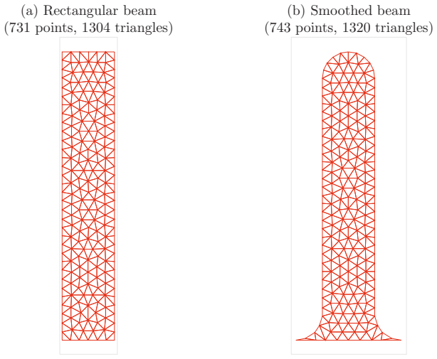
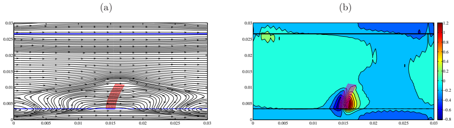
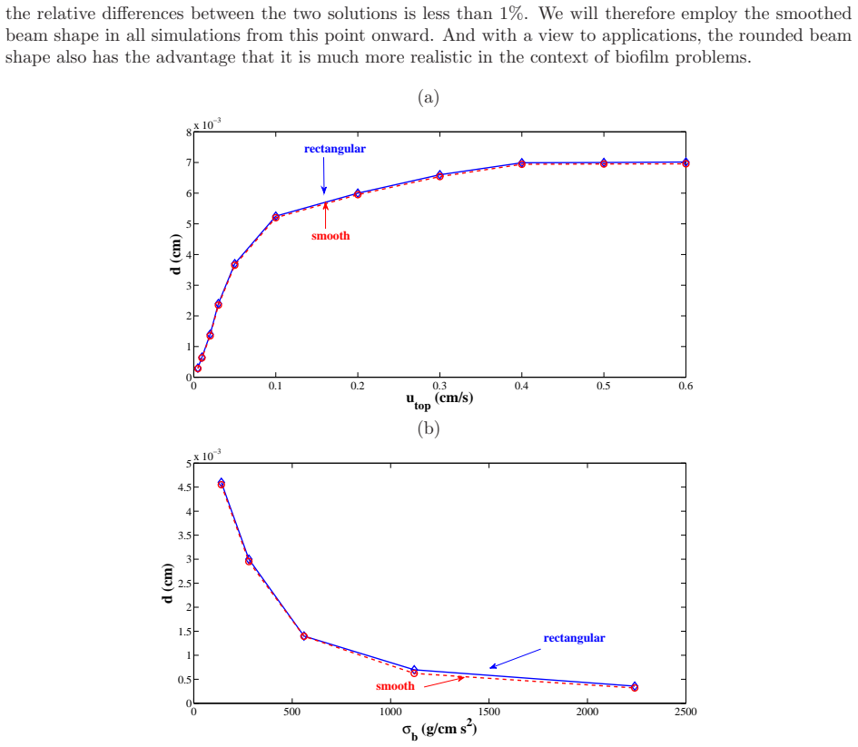
The central claim is that the immersed-boundary spring-network model, with a uniform stiffness sigma_b on each link, produces cantilever deflection that scales as d proportional to $sigma_b^{{-0.8995}}$ and d proportional to $H_b^{{3.8094}}$, in close agreement with the Euler-Bernoulli predictions d proportional to 1/EI and d proportional to $H_b^{4}$; the paper interprets this as evidence that the effective flexural rigidity of the triangulated structure is proportional to sigma_b. For the porous extension, replacing the no-slip fiber equation with the Darcy slip velocity u_p = -(K/mu) grad p gives a deflection that is unchanged for K less than about $10^{-8}$, slightly increased for intermediate permeability, and strongly decreased for high permeability as flow passes through the beam. The paper further shows that replacing sharp corners by circular fillets eliminates the non-physical kinks and protrusions at the free and fixed ends, with a relative change in tip deflection under 1%.
Load-bearing premise
The results rest on the assumption that the uniform spring network with stiffness sigma_b behaves as a continuum elastic beam whose flexural rigidity EI is a fixed constant multiple of sigma_b; the paper explicitly leaves the derivation of EI proportional to sigma_b to future work.
Editorial extensions
If this is right
- Within the reported parameter range, the spring network can serve as a faithful stand-in for a thin elastic cantilever in shear flow, so subsequent studies of biologically motivated beams can trust the deflection scaling without resolving the continuum solid.
- The porosity model gives a handle on how much flow passes through a deformable structure: below a permeability threshold the beam is effectively solid, and above it the same shear produces less deformation.
- Smoothing the beam's corners is a cheap fix for the non-physical end distortions, with a tip-deflection penalty below 1%.
- The three-regime response to shear velocity (linear, transitional, saturated) can be used to predict when a beam ceases to deform further as flow strength grows.
Reading between the lines
- The observed exponents (-0.8995 and 3.8094) deviate from the ideal integers by a few percent; this may reflect finite-thickness or discrete-network corrections that could be tested by refining the triangle mesh and checking whether the exponents converge to exactly -1 and 4.
- The non-monotonic deflection in the mid-range of permeability suggests two competing effects—enhanced horizontal fluid transport that increases the shear load versus reduced blockage—and could be mapped to a dimensionless Darcy number for a collapse of the data.
- If the EI proportional to sigma_b relation can be derived analytically, the method would become a parameter-free bridge between a discrete spring network and continuum beam theory, allowing the same computational setup to be used for arbitrary beam shapes without recalibration.
Signed reviews
Editorial analysis
A structured set of objections, weighed in public.
Referee Report
Summary. This paper develops a two-dimensional immersed boundary (IB) model of a cantilever beam attached to a wall inside a Couette shear flow. The beam is discretized as a triangulated network of springs with stiffness σb, and the fluid is described by the incompressible Navier-Stokes equations with IB forcing. The authors measure the steady tip deflection d as σb, beam length Hb, and top-wall velocity utop are varied; report power-law fits d ∝ σ_b^{-0.8995} and d ∝ H_b^{3.8094}; compare these with Euler-Bernoulli predictions; investigate corner irregularities and propose a smoothed 'fillet' shape; and extend the IB formulation to porous beams via Darcy slip (Eqs. 14–15), reporting the dependence of d on permeability K. The central stated goal is qualitative comparison with linear beam theory and a demonstration that the spring-network IB model yields physically plausible deflection behavior.
Significance. The paper addresses a relevant problem in fluid-structure interaction and bio-inspired flows. Its strengths are the clear presentation of the IB spring-network discretization, the explicit treatment of corner artifacts, and the extension of porous IB boundaries to a 2D solid region. The power-law fits are reported with normalized RMS errors and the flow visualizations are informative. However, the quantitative link between the spring-network stiffness and a continuum flexural rigidity is not established, the scaling exponents are fitted over a range that includes large deflections, and the porous model is an unvalidated postulate. The paper's contribution is therefore best viewed as a computational parameter study rather than a fully validated quantitative model. If the missing calibration and model validation are provided, the paper would have clear value for biofilm and cilia modeling.
major comments (4)
- [Section 3.2, Section 5] The paper interprets d ∝ σ_b^{-0.8995} as evidence that the effective flexural rigidity EI is proportional to σ_b. This inference requires the Euler-Bernoulli relation d ∝ 1/EI to hold for the spring network, but the equivalence between the spring-network parameters and EI is never established; Section 5 explicitly defers this to future work. Without an independent calibration, e.g., applying a known static load to the isolated spring network and fitting EI from the Euler-Bernoulli solution, the exponent agreement is an empirical power-law fit rather than a validation of continuum beam theory. This point is load-bearing for the paper's central comparison.
- [Section 3.2, Figure 4] The power-law fit in Figure 4b includes configurations with d/H_b as large as 0.65, which is outside the small-deflection assumption underlying Eq. (13). Because the large-deflection points are systematically included, the fitted exponent -0.8995 may deviate from -1 due to geometric nonlinearity rather than to any intrinsic relation between EI and σ_b. The authors should report fits restricted to the linear regime (e.g., d/H_b < 0.1) and show that the exponent is stable.
- [Section 3.1, Section 3.3, Figure 5] The Euler-Bernoulli comparisons in §3.1 use a constant load and a load that decreases linearly from a maximum at the wall. In the simulated linear shear flow with no-slip at the bottom wall, the undisturbed load on a vertical beam is zero at the wall and grows with height; for a load q(y) ∝ y, the tip deflection is d = 11 q' H_b^5/(120 EI), scaling as H_b^5 rather than H_b^4 at fixed shear rate. The measured H_b^{3.8094} is therefore not directly comparable to the m=4 benchmark unless the actual load distribution is computed and its dependence on H_b is accounted for.
- [Section 4.1, Eqs. (14)–(15)] The porous-beam model is introduced as a postulate. Equation (15) states that the fiber moves with velocity -u_p + ∫ u δ, with u_p = -(K/μ)∇p, but no derivation, limiting-case check, or comparison against existing porous IB models (e.g., the 1D membrane limit of Kim and Peskin [18] or Stockie [19]) is provided. The physical interpretation of the negative sign is asserted but not tested. Because the permeability results in Section 4 are presented as predictions of the model, the authors should validate the porous formulation in a simple geometry against a known solution or against the non-porous limit.
minor comments (6)
- [Section 3.4, table] For utop=0.003, the listed ratio ‖u‖/utop is 0.17, which is not close to 0.1; the statement that the ratio is approximately 0.1 for all cases should be corrected or rephrased.
- [Section 4.1, paragraph] The phrase 'In this thesis' should read 'In this paper.'
- [Section 5, conclusions] 'Filled or round' should read 'filleted or rounded' in the sentence about smoothing the corners.
- [Section 2.1] The units of fIB are written as [g/s^2], but as a body force in the Navier-Stokes equations it should have units of force per unit volume, e.g., [g/(cm^2 s^2)]; please check the units of fIB and FIB for consistency.
- [Section 3.2, Section 3.3] The 'normalized RMS error' is not defined; please state the normalization used and the number of data points in the least-squares fits.
- [Figure 2b] The caption says the fillets have diameter equal to the beam width, but the text in Section 3.5 refers to circular arcs; specify the radius or arc geometry explicitly.
Circularity Check
Minor built-in σ_b scaling presented as material-property inference; otherwise simulations are self-contained against externally stated beam theory.
-
other
[Section 3.2, Eq. (9)]
"Assuming that the linear theory holds here (thin beam, small deflection) our computational results suggest that the effective flexural rigidity of our triangulated spring link structure is directly proportional to the spring stiffness, or in other words that EI ∝ σb."
Equation (9) defines the beam IB force as a linear spring law: F_b^ℓ = Σ_m σ_b I_{ℓm} (d_{ℓm}(0) − d_{ℓm}) d_{ℓm}/d_{ℓm}. For a fixed external fluid load, any equilibrium displacement therefore scales inversely with σ_b by construction. The observed d ∝ σ_b^{−0.8995} and the resulting suggestion 'EI ∝ σb' thus restate the model's linear-spring input under the name of an effective flexural rigidity, rather than independently testing the Euler-Bernoulli relation d ∝ 1/EI. The paper itself acknowledges that this relationship is not derived and defers it to future work (Section 5). The H_b scaling and porous-beam results are not affected by this step.
full rationale
The paper is a numerical study whose central outputs are steady-state tip deflections computed from an IB spring-network model. The Euler-Bernoulli formulas in Section 3.1 are quoted from an external textbook and serve as an independent benchmark. The σ_b test is the only near-circular step: because Eq. (9) is a linear spring law with stiffness σ_b, equilibrium deflection under a roughly fixed fluid load scales as 1/σ_b by definition; the inference EI ∝ σb is therefore an interpretation of a built-in model property, not an independent validation. Section 5 explicitly lists EI ∝ σb as future work, so the paper does not conceal the gap. The H_b-scaling study (Section 3.3) is genuinely independent: mesh geometry and load distribution change with beam length, and the fitted exponent 3.8094 is compared with the externally stated EB value 4. The porous extension (Section 4) is a stated Darcy-type postulate with qualitative consequences that are not used to define permeability. Self-citations [20,21] supply numerical algorithm details but are not load-bearing for the scaling claims. Overall, the derivation chain is self-contained and the flagged step is minor.
Assumptions & free parameters
free parameters (2)
- Power-law exponent for d vs sigma_b =
-0.8995
- Power-law exponent for d vs Hb =
3.8094
assumptions (6)
- standard math Incompressible Newtonian fluid satisfies Navier-Stokes equations (eqs. 1-2).
- domain assumption The immersed boundary method uses periodic boundary conditions in x and y and stiff tether springs to hold the walls (Section 2.2.1).
- domain assumption The beam is represented by a triangulated network of linear springs with uniform stiffness sigma_b, based on the Alpkvist-Klapper biofilm model (eq. 9).
- domain assumption Euler-Bernoulli beam theory with constant or linearly varying load applies to the small-deflection cases used for comparison (Section 3.1).
- domain assumption Darcy's law with a single scalar permeability K relates the porous slip velocity to the local pressure gradient (eq. 14).
- ad hoc to paper The porous fiber evolves according to dX/dt = -up + integral(u delta) (eq. 15), with the structure moving opposite to the Darcy slip velocity.
Cite this review
Pith. "Pith review of Immersed boundary simulations of fluid shear-induced deformation of a cantilever beam." pith.science (2026). https://pith.science/paper/SAYUZDVI
@misc{pith2026190801560,
  author       = {Pith},
  title        = {Pith review of: Immersed boundary simulations of fluid shear-induced deformation of a cantilever beam},
  year         = {2026},
  howpublished = {\url{https://pith.science/paper/SAYUZDVI}},
  note         = {Machine review of arXiv:1908.01560}
}
read the original abstract
We derive a mathematical model and the corresponding computational scheme to study deflection of a two-dimensional elastic cantilever beam immersed in a channel, where one end of the beam is fixed to the channel wall. The immersed boundary method has been employed to simulate numerically the fluid-structure interaction problem. We investigate how variations in physical and numerical parameters change the effective material properties of the elastic beam and compare the results qualitatively with linear beam theory. We also pay careful attention to "corner effects" -- irregularities in beam shape near the free and fixed ends -- and show how this can be remedied by smoothing out the corners with a "fillet" or rounded shape. Finally, we extend the immersed boundary formulation to include porosity in the beam and investigate the effect that the resultant porous flow has on beam deflection.
Figures

Figures from the paper (9 more)




Reference graph
Works this paper leans on
-
[18]
Y. Kim, C. S. Peskin, 2–d parachute simulation by the imm ersed boundary method, SIAM Journal on Scientific Computing 28 (6) (2006) 2294–2312
work page 2006
-
[19]
J. M. Stockie, Modelling and simulation of porous immer sed boundaries, Computers & Structures 87 (11) (2009) 701–7 09
work page 2009
-
[1]
E. Alpkvist, I. Klapper, Description of mechanical resp onse including detachment using a novel particle model of biofilm/flow interaction, W ater Science and Technology 55 (8 -9) (2007) 265–273
work page 2007
- [2]
- [3]
-
[4]
C. Pozrikidis, Shear flow over cylindrical rods attached to a substrate, Journal of Fluids and Structures 26 (3) (2010 ) 393–405
work page 2010
-
[5]
C. Pozrikidis, Shear flow past slender elastic rods attac hed to a plane, International Journal of Solids and Structur es 48 (1) (2011) 137–143
work page 2011
-
[6]
Y. Farjoun, D. G. Schaeffer, A thin cantilever beam in a flow , in: AIP Conference Proceedings, Vol. 1389, 2011, pp. 1446–1449. 16
work page 2011
Show all 28 references
-
[7]
L. P. Li, K. Schulgasser, G. Cederbaum, Theory of poroela stic beams with axial diffusion, Journal of the Mechanics and Physics of Solids 43 (12) (1995) 2023–2042
1995
-
[8]
A. Goza, T. Colonius, A strongly-coupled immersed-boun dary formulation for thin elastic structures, Journal of Co mpu- tational Physics 136 (2017) 401–411
2017
-
[9]
X. Yang, C. W ang, A nonlinear mathematical model for larg e deflection of incompressible saturated poroelastic beams , Applied Mathematics and Mechanics (English Edition) 28 (12 ) (2007) 1587–1595
2007
-
[10]
L. P. Li, K. Schulgasser, G. Cederbaum, Large deflection analysis of poroelastic beams, International Journal of No nlinear Mechanics 33 (1) (1998) 1–14
1998
-
[11]
X. Yang, Q. W en, Dynamic and quasi-static bending of sat urated poroelastic timoshenko cantilever beam, Applied Ma th- ematics and Mechanics (English Edition) 31 (8) (2010) 995–1 008
2010
-
[12]
L. J. Fauci, R. Dillon, Biofluidmechanics of reproducti on, Annu. Rev. Fluid Mech. 38 (2006) 371–394
2006
-
[13]
C. S. Peskin, The immersed boundary method, Acta numeri ca 11 (2002) 479–517
2002
-
[14]
C. S. Peskin, Flow patterns around heart valves: a numer ical method, Journal of computational physics 10 (2) (1972) 252–271
1972
-
[15]
Dillon, L
R. Dillon, L. Fauci, A microscale model of bacterial and biofilm dynamics in porous media, Biotechnology and Bioengi - neering 68 (5) (2000) 536–547
2000
-
[16]
R. H. Dillon, L. J. Fauci, C. Omoto, X. Yang, Fluid dynami c models of flagellar and ciliary beating, Annals of the New York Academy of Sciences 1101 (1) (2007) 494–505
2007
-
[17]
E. A. Schwartz, M. L. Leonard, R. Bizios, S. S. Bowser, An alysis and modeling of the primary cilium bending response t o fluid shear, American Journal of Physiology-Renal Physiolo gy 272 (1) (1997) F132–F138
1997
-
[20]
Ghosh, The immersed boundary method for simulating g ravitational settling and fluid shear-induced deformation of elastic structures, Ph.D
S. Ghosh, The immersed boundary method for simulating g ravitational settling and fluid shear-induced deformation of elastic structures, Ph.D. thesis, Science: Department of M athematics (2013)
2013
-
[21]
Ghosh, J
S. Ghosh, J. M. Stockie, Numerical simulations of parti cle sedimentation using the immersed boundary method, Comm u- nications in Computational Physics 18 (02) (2015) 380–416
2015
-
[22]
P. O. Persson, G. Strang, A simple mesh generator in matl ab, SIAM review 46 (2) (2004) 329–345
2004
-
[23]
Z. J. Huang, J. M. Tarbell, Numerical simulation of mass transfer in porous media of blood vessel walls, American Jou rnal of Physiology-Heart and Circulatory Physiology 273 (1) (19 97) H464–H477
-
[24]
M. C. M. van Loosdrecht, J. J. Heijnen, H. Eberl, J. Kreft , C. Picioreanu, Mathematical modelling of biofilm structur es, Antonie van Leeuwenhoek 81 (2002) 245–256
2002
-
[25]
V. T. Nguyen, E. Morgenroth, H. J. Eberl, A mesoscale mod el for hydrodynamics in biofilms that takes microscopic flow effects into account, W ater science and technology 52 (7) (20 05) 167–172
-
[26]
Thullner, P
M. Thullner, P. Baveye, Computational pore network mod eling of the influence of biofilm permeability on bioclogging in porous media, Biotechnology and Bioengineering 99 (6) (200 8) 1337–1351
-
[27]
Davit, H
Y. Davit, H. Byrne, J. Osborne, J. Pitt-Francis, D. Gava ghan, M. Quintard, Hydrodynamic dispersion within porous biofilms, Physical Review E 87 (1) (2013) 012718
2013
-
[28]
A. T. Layton, Modeling water transport across elastic b oundaries using an explicit jump method, SIAM Journal on Scientific Computing 28 (6) (2006) 2189–2207. 17
2006
Reviewed August 14, 2026 · model on record in the stance chip above.
Discussion (0). Continue with ORCID to comment.