REVIEW 3 major objections 6 minor 53 references
A versatile digital approach to laser frequency comb stabilization
T0 review · 3 major / 6 minor · reviewed 2026-08-14 · deepseek-v4-flash
Pith's one-line read A low-cost FPGA board phase-locks a commercial laser frequency comb for 30 hours without a single cycle slip.
desk verdict A solid, incremental demonstration that a low-cost FPGA digital PLL can match manufacturer electronics for comb stabilization; worth a referee, with a few reporting gaps to fix. read the letter →
The pith
A machine-rendered reading of the paper's core claim, the machinery that carries it, and where it could break.
The reading
What carries the argument
The work's load-bearing object is an FPGA-based digital phase-locked loop: the board digitizes the optical beat note, mixes it with digitally synthesized I/Q reference frequencies to extract a phase error, forms a frequency error from the one-clock-cycle difference of that phase, and passes it through a loop filter with proportional, integral, double-integral, and differential terms (PII2D). Two such loops run in parallel, one for $f_\text{ceo}$ and one for $f_\text{beat}$, and each is backed by a slow auxiliary servo (a 10 Hz current controller on the $f_\text{ceo}$ modulator's thermoelectric cooler and a 1 Hz piezo driver in the laser cavity) that keeps the fast electro-optic actuators centered. This two-tier architecture is what lets the fast loop provide ~100 kHz bandwidth and sub-0.1 rad residual phase while the slow loops absorb long-term drift, sustaining a slip-free lock beyond a day. The same FPGA simultaneously records the error signals, which is how a single platform acts as its own phase-noise analyzer and frequency counter.
What would settle it
Record the phase-error signal out of loop during a 30-hour lock and scan for any discrete $2\pi$ jump in a phase record sampled faster than the counter gate time; if one appears, the claimed slip-free duration is not valid. A simpler version: inspect the counter time series for adjacent pairs whose difference exceeds the expected drift plus counter dead time — that pattern is the signature of a hidden cycle slip.
Extended reading notes
Core claim
The central claim is that a generic digital phase-locked loop implemented on a low-cost FPGA board—rather than in analog circuits or vendor-specific digital boxes—can simultaneously stabilize the carrier-envelope offset frequency $f_\text{ceo}$ and the repetition rate $f_\text{rep}$ of a commercial Er:fiber comb to a level comparable with the laser's own control electronics. The paper reports integrated phase noise of 41 mrad on the optical beat note $f_\text{beat}$ and 114 mrad on $f_\text{ceo}$ (100 Hz to 2 MHz), corresponding to 70 as timing jitter, and cycle-slip-free locking maintained over a continuous 30-hour run. It also shows the same hardware can lock the repetition rate directly in the radio-frequency domain simply by switching inputs and recalling saved PID settings, with the optical beat note roughly 400,000 times more sensitive to the repetition-rate actuator than the RF beat note, as the comb equation predicts.
Load-bearing premise
The 30-hour cycle-slip-free claim assumes the external frequency-counter records shown in Fig. 6 catch every skipped cycle, but the paper gives no threshold or algorithm for identifying slips, so a brief $2\pi$ phase excursion between counter gates would go unnoticed.
Editorial extensions
If this is right
- Phase noise of 41 mrad on $f_\text{beat}$ and 114 mrad on $f_\text{ceo}$ (100 Hz to 2 MHz) puts the lock within a factor of 1–2 of the manufacturer's quoted 43 and 85 mrad, so the low-cost board is not the limiting element.
- The 70 attosecond integrated timing jitter satisfies the jitter budget of broadband dual-comb spectroscopy and is below current requirements for optical ranging and fiber-network timing transfer.
- Because the same board can lock the repetition rate optically or in the RF domain by switching ADC input and recalling saved PID settings, one platform replaces two distinct control chains.
- The slow servos keep the fast EOMs centered over long intervals, which is what allows continuous slip-free locking beyond 30 hours.
- The board's built-in diagnostics mean that locking and characterization need no separate spectrum analyzer, phase-noise analyzer, or frequency counter.
Reading between the lines
- An immediate testable extension is to add an out-of-loop cycle-slip detector to the same FPGA firmware; because the paper specifies no slip-detection threshold for the 30-hour claim, an independent counter of $2\pi$ phase jumps would make the lock-duration number self-verifying.
- The measured ~400,000-fold sensitivity difference between the RF and optical beat notes to the repetition-rate actuator could be used as a quick diagnostic: measuring that ratio on a new comb predicts how much leverage an optical lock will provide before building the full setup.
- The software-defined nature of the loop filter suggests the same board could phase-lock noisier or broader-linewidth sources than the manufacturer laser used here, since capture range and filter shape can be retuned without hardware changes; the paper does not demonstrate this.
- The paper's own in-loop bias caveat implies that anyone replicating the results should report out-of-loop phase noise, not the internal counter, when comparing lock quality; adopting that habit in future FPGA-based comb papers would make published stability numbers more directly comparable.
Signed reviews
Editorial analysis
A structured set of objections, weighed in public.
Referee Report
Summary. The paper reports a digital servo system for stabilizing the repetition rate and carrier-envelope offset frequency of a commercial Er:fiber frequency comb. The system uses two low-cost Red Pitaya 125-14 FPGA boards running open-source digital phase-locked-loop software, with slow and fast actuators on the laser. The authors claim cycle-slip-free locking of optically derived beatnotes over a 30 hour period, integrated phase noise of 41 mrad and 114 mrad for f_beat and f_ceo over 100 Hz to 2 MHz, and a corresponding timing jitter of 70 attoseconds, which they argue is comparable to manufacturer-supplied lock electronics and sufficient for precision comb applications. The paper also demonstrates direct RF locking of the repetition rate by reconfiguring the same FPGA platform.
Significance. If the claims hold, this is a valuable demonstration: it shows that an inexpensive, commercially available FPGA board combined with open-source code can replace manufacturer-specific laser lock electronics without degrading short-term phase noise or long-term lock duration, lowering the cost and complexity barrier for frequency comb stabilization. The paper's strengths include out-of-loop phase-noise measurements made with a signal analyzer, long-term monitoring with external frequency counters, a benchmark against the laser manufacturer's specified phase noise, and a public code repository. The central short-term phase-noise result appears well supported. However, the headline long-term claim of 30-hour cycle-slip-free operation needs a more rigorous and clearly documented detection methodology, and there is an internal inconsistency in the assignment of the integrated phase-noise values that must be resolved before the comparison to manufacturer values can be assessed.
major comments (3)
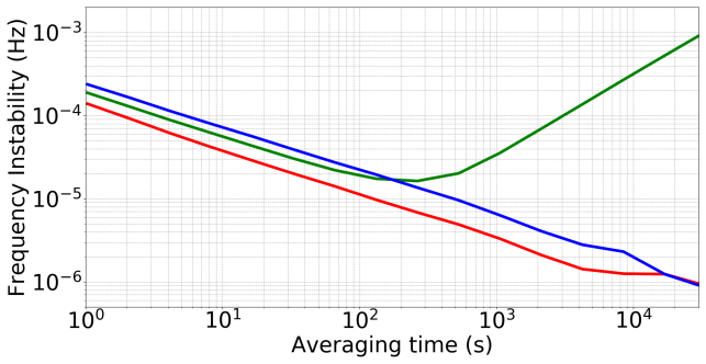
- [§3.2, Fig. 6] The 30-hour cycle-slip-free claim is not backed by a defined slip-detection procedure. The paper should state the Agilent 53132A counter's gate time, dead time, measurement mode, number of samples, and any outlier-rejection or threshold criteria used to declare the data slip-free. With a gated counter, a brief 2π phase excursion occurring during dead time, or a transient that is averaged over a long gate, could be hidden in the displayed statistics. The quoted standard deviations of 0.1-0.2 mHz are only meaningful if every gate was continuously recorded; a single cycle slip within a 1 s gate would shift the counted frequency by roughly 1 Hz and would be visible only if that gate were included in the analysis. Please provide the raw time series or the analysis script used to establish the slip-free determination.
- [§3.1, Fig. 5] The integrated phase-noise values are assigned inconsistently between the text and the figure caption. Section 3.1 states that the integrated phase noise is 114 mrad for f_ceo and 41 mrad for f_beat, and the conclusions repeat the 41 mrad / 114 mrad pairing, but the Fig. 5 caption assigns 114 mrad to f_beat and 40 mrad to f_ceo. This directly affects the central claim that the digital servo performs comparably to the manufacturer's values of 85 mrad and 43 mrad, because swapping the labels changes which lock is compared to which specification. The caption and text must be reconciled, and the corresponding value should be used consistently in the abstract and conclusions.
- [§3.1] The manufacturer comparison is not fully specified. The statement that 'the laser's manufacturer reports values of 85 mrad and 43 mrad' is given without a citation or a statement of the bandwidth and measurement conditions for those values. If the manufacturer's numbers are integrated over a different band, or were obtained with different loop gain settings, the conclusion that the Red Pitaya is not a significant limitation is not established. Please provide the source of the manufacturer values and confirm that the comparison is over the same 100 Hz to 2 MHz integration range.
minor comments (6)
- [Abstract / §3.1] The abstract says 'residual phase noise at or below ~0.1 rad,' but the reported f_ceo value of 114 mrad exceeds 100 mrad; either relax the wording or state explicitly that 0.1 rad is an approximate bound.
- [§3.1] The calculation of the 70 attosecond timing jitter is not shown. Please state the formula and the carrier frequency or optical frequency used, so that a reader can reproduce the conversion from integrated phase noise to timing jitter.
- [§3.2, Fig. 6] Please clarify how the reported frequency deviations and standard deviations are computed, especially for f_rep, which is described as having a linear drift corrected before the 0.1 mHz standard deviation is calculated.
- [§1] The phrase 'up to 222π radians' appears to be a typesetting artifact; it should read 'up to 2^22 π radians' if that is the intended claim.
- [§3.2] The text says that the optically derived f_ceo and f_beat are 'in-loop measurements' in the Allan deviation discussion, while earlier the paper states that the reported measurements were made with instruments 'out of loop to the phase locks'; please reconcile this terminology.
- [Table 1] In Table 1, the 'Modulation Control' row for the slow f_beat path lists '0 to 1 V' while the other paths list '-1 to 1 V'; please confirm this is intentional and clarify the voltage convention.
Circularity Check
No significant circularity: lock performance is measured with external counters and analyzers, not derived from the servo equations.
full rationale
The paper is an experimental characterization, not a derivation. The headline phase-noise and timing-jitter numbers (Sec. 3.1) are measured out-of-loop with an Agilent MXA N9020A signal analyzer and explicitly compared to manufacturer values; the long-term lock statistics (Sec. 3.2) come from external Agilent 53132A frequency counters, and the paper explicitly notes that in-loop FPGA diagnostics would be biased and therefore avoids using them for the reported values (Sec. 3 opening). The servo firmware is attributed to an external open-source project (Refs. 35, 46) rather than being claimed as derived here. Self-citations in the introduction are background references to comb metrology and do not provide the load-bearing evidence for the lock performance. The only weakness noted by the skeptic is that the 'cycle-slip free' declaration in Sec. 3.2 lacks a stated slip-detection threshold or counter gate/dead-time analysis; that is a measurement-analysis and reporting limitation, not a circularity in which a predicted quantity reduces to a fitted input by construction. No equation or claim in the paper is equivalent to its own input, so the circularity score is 0.
Assumptions & free parameters
free parameters (1)
- PID loop gains and slow-servo integrator time constants =
not reported
assumptions (4)
- standard math The comb equation nu_n = n f_rep + f_ceo relates the optical beat notes to the controlled degrees of freedom.
- domain assumption The f-2f and 1550 nm heterodyne error signals faithfully represent the comb's phase coherence.
- domain assumption The shared hydrogen-maser reference and the external counters and signal analyzer are stable enough to resolve the quoted phase noise and frequency deviations.
- domain assumption The manufacturer's reported phase-noise values (85 and 43 mrad) are directly comparable to the measured values.
Cite this review
Pith. "Pith review of A versatile digital approach to laser frequency comb stabilization." pith.science (2026). https://pith.science/paper/TARXHKFQ
@misc{pith2026190809212,
  author       = {Pith},
  title        = {Pith review of: A versatile digital approach to laser frequency comb stabilization},
  year         = {2026},
  howpublished = {\url{https://pith.science/paper/TARXHKFQ}},
  note         = {Machine review of arXiv:1908.09212}
}
read the original abstract
We demonstrate the use of a flexible digital servo system for the optical stabilization of both the repetition rate and carrier-envelope offset frequency of a laser frequency comb. The servo system is based entirely on a low-cost field programmable gate array, simple electronic components, and existing open-source software. Utilizing both slow and fast feedback actuators of a commercial mode-locked laser frequency comb, we maintain cycle-slip free locking of optically-derived beatnotes over a 30 hour period, and measure residual phase noise at or below ~0.1 rad, corresponding to <100 attosecond timing jitter on the optical phase locks. This stability is sufficient for high-precision frequency comb applications, and indicates comparable performance to existing frequency control systems. The modularity of this system allows for it to be easily adapted to suit the servo actuators of a wide variety of laser frequency combs and continuous-wave lasers, reducing cost and complexity barriers, and enabling digital phase control in a wide range of settings.
Figures


Figures from the paper (4 more)


Reference graph
Works this paper leans on
-
[1]
Nobel lecture: Defining and measuring optical frequencies,
J. L. Hall, “Nobel lecture: Defining and measuring optical frequencies,” Rev. Mod. Phys.78, 1279–1295 (2006)
work page 2006
-
[2]
Nobel lecture: Passion for precision,
T. W. Hänsch, “Nobel lecture: Passion for precision,” Rev. Mod. Phys.78, 1297–1309 (2006)
work page 2006
-
[3]
The evolving optical frequency comb,
S. A. Diddams, “The evolving optical frequency comb,” J. Opt. Soc. Am. B27, B51–B62 (2010)
work page 2010
-
[4]
A frequency comb in the extreme ultraviolet,
C. Gohle, T. Udem, M. Herrmann, J. Rauschenberger, R. Holzwarth, H. A. Schuessler, F. Krausz, and T. W. Hänsch, “A frequency comb in the extreme ultraviolet,” Nature436, 234–237 (2005)
work page 2005
-
[5]
Direct frequency comb spectroscopy in the extreme ultraviolet,
A. Cingöz, D. C. Yost, T. K. Allison, A. Ruehl, M. E. Fermann, I. Hartl, and J. Ye, “Direct frequency comb spectroscopy in the extreme ultraviolet,” Nature482, 68 EP – (2012)
work page 2012
-
[6]
Infrared electric field sampled frequency comb spectroscopy,
A. S. Kowligy, H. Timmers, A. J. Lind, U. Elu, F. C. Cruz, P. G. Schunemann, J. Biegert, and S. A. Diddams, “Infrared electric field sampled frequency comb spectroscopy,” Sci. Adv.5(2019)
work page 2019
-
[7]
Molecular fingerprinting with bright, broadband infrared frequency combs,
H. Timmers, A. Kowligy, A. Lind, F. C. Cruz, N. Nader, M. Silfies, G. Ycas, T. K. Allison, P. G. Schunemann, S. B. Papp, and S. A. Diddams, “Molecular fingerprinting with bright, broadband infrared frequency combs,” Optica5, 727–732 (2018)
work page 2018
-
[8]
A monolithic optical frequency comb generator,
M. Kourogi, T. Enami, and M. Ohtsu, “A monolithic optical frequency comb generator,” Photonics Technol. Lett. IEEE 6, 214 – 217 (1994)
work page 1994
Show all 53 references
-
[9]
Ultrafast electro-optic light with subcycle control,
D. R. Carlson, D. D. Hickstein, W. Zhang, A. J. Metcalf, F. Quinlan, S. A. Diddams, and S. B. Papp, “Ultrafast electro-optic light with subcycle control,” Science361, 1358–1363 (2018)
2018
-
[10]
Dissipativekerrsolitonsinopticalmicroresonators,
T.J.Kippenberg,A.L.Gaeta,M.Lipson,andM.L.Gorodetsky,“Dissipativekerrsolitonsinopticalmicroresonators,” Science 361 (2018)
2018
-
[11]
Microresonator-based optical frequency combs,
T. J. Kippenberg, R. Holzwarth, and S. A. Diddams, “Microresonator-based optical frequency combs,” Science332, 555–559 (2011)
2011
-
[12]
Optical frequency comb generation from a monolithic microresonator,
P. Del’Haye, A. Schliesser, O. Arcizet, T. Wilken, R. Holzwarth, and T. J. Kippenberg, “Optical frequency comb generation from a monolithic microresonator,” Nature450, 1214 EP – (2007)
2007
-
[13]
An optical-frequency synthesizer using integrated photonics,
D. T. Spencer, T. Drake, T. C. Briles, J. Stone, L. C. Sinclair, C. Fredrick, Q. Li, D. Westly, B. R. Ilic, A. Bluestone, N. Volet, T. Komljenovic, L. Chang, S. H. Lee, D. Y. Oh, M.-G. Suh, K. Y. Yang, M. H. P. Pfeiffer, T. J. Kippenberg, E. Norberg, L. Theogarajan, K. Vahala, ...
2018
-
[14]
Architecture for the photonic integration of an optical atomic clock,
Z. L. Newman, V. Maurice, T. Drake, J. R. Stone, T. C. Briles, D. T. Spencer, C. Fredrick, Q. Li, D. Westly, B. R. Ilic, B. Shen, M.-G. Suh, K. Y. Yang, C. Johnson, D. M. S. Johnson, L. Hollberg, K. J. Vahala, K. Srinivasan, S. A. Diddams, J. Kitching, S. B. Papp, and M. T. Hu...
2019
-
[15]
A920-kilometeropticalfiberlinkforfrequencymetrologyatthe19thdecimalplace,
K. Predehl, G. Grosche, S. M. F. Raupach, S. Droste, O. Terra, J. Alnis, T. Legero, T. W. Hänsch, T. Udem, R.Holzwarth, andH.Schnatz, “A920-kilometeropticalfiberlinkforfrequencymetrologyatthe19thdecimalplace,” Science 336, 441–444 (2012)
2012
-
[16]
Simultaneous remote transfer of accurate timing and optical frequency over a public fiber network,
O.Lopez,A.Kanj,P.-E.Pottie,D.Rovera,J.Achkar,C.Chardonnet,A.Amy-Klein,andG.Santarelli,“Simultaneous remote transfer of accurate timing and optical frequency over a public fiber network,” Appl. Phys. B110, 3–6 (2013)
2013
-
[17]
Optical two-way time and frequency transfer over free space,
F. R. Giorgetta, W. C. Swann, L. C. Sinclair, E. Baumann, I. Coddington, and N. R. Newbury, “Optical two-way time and frequency transfer over free space,” Nat. Photonics7, 434 EP – (2013)
2013
-
[18]
Optical atomic clocks,
A. D. Ludlow, M. M. Boyd, J. Ye, E. Peik, and P. O. Schmidt, “Optical atomic clocks,” Rev. Mod. Phys.87, 637–701 (2015)
2015
-
[19]
Dual-comb spectroscopy,
I. Coddington, N. Newbury, and W. Swann, “Dual-comb spectroscopy,” Optica3, 414–426 (2016)
2016
-
[20]
Frequency comb spectroscopy,
N. Picqué and T. W. Hänsch, “Frequency comb spectroscopy,” Nat. Photonics13, 146–157 (2019)
2019
-
[21]
Frequency-comb infrared spectrometer for rapid, remote chemical sensing,
A. Schliesser, M. Brehm, F. Keilmann, and D. W. van der Weide, “Frequency-comb infrared spectrometer for rapid, remote chemical sensing,” Opt. Express13, 9029–9038 (2005)
2005
-
[22]
Mid-infrared dual-comb spectroscopy with an optical parametric oscillator,
Z. Zhang, T. Gardiner, and D. T. Reid, “Mid-infrared dual-comb spectroscopy with an optical parametric oscillator,” Opt. Lett.38, 3148–3150 (2013)
2013
-
[23]
High-accuracy measurement of 240-m distance in an optical tunnel by use of a compact femtosecond laser,
K. Minoshima and H. Matsumoto, “High-accuracy measurement of 240-m distance in an optical tunnel by use of a compact femtosecond laser,” Appl. Opt.39, 5512–5517 (2000)
2000
-
[24]
Rapid and precise absolute distance measurements at long range,
I. Coddington, W. C. Swann, L. Nenadovic, and N. R. Newbury, “Rapid and precise absolute distance measurements at long range,” Nat. Photonics3, 351 EP – (2009). Article
2009
-
[25]
Laser frequency combs for astronomical observations,
T. Steinmetz, T. Wilken, C. Araujo-Hauck, R. Holzwarth, T. W. Hänsch, L. Pasquini, A. Manescau, S. D’Odorico, M. T. Murphy, T. Kentischer, W. Schmidt, and T. Udem, “Laser frequency combs for astronomical observations,” Science 321, 1335–1337 (2008)
2008
-
[26]
A spectrograph for exoplanet observations calibrated at the centimetre- per-second level,
T. Wilken, G. L. Curto, R. A. Probst, T. Steinmetz, A. Manescau, L. Pasquini, J. I. González Hernández, R. Rebolo, T. W. Hänsch, T. Udem, and R. Holzwarth, “A spectrograph for exoplanet observations calibrated at the centimetre- per-second level,” Nature485, 611 EP – (2012)
2012
-
[27]
Stellar spectroscopy in the near-infrared with a laser frequency comb,
A. J. Metcalf, T. Anderson, C. F. Bender, S. Blakeslee, W. Brand, D. R. Carlson, W. D. Cochran, S. A. Diddams, M.Endl,C.Fredrick,S.Halverson,D.D.Hickstein,F.Hearty,J.Jennings,S.Kanodia,K.F.Kaplan,E.Levi,E.Lubar, S. Mahadevan, A. Monson, J. P. Ninan, C. Nitroy, S. Osterman, S. ...
2019
-
[28]
Measuring the frequency of light with mode-locked lasers,
J. Reichert, R. Holzwarth, T. Udem, and T. Hänsch, “Measuring the frequency of light with mode-locked lasers,” Opt. Commun. 172, 59 – 68 (1999)
1999
-
[29]
Optical frequency metrology,
T. Udem, R. Holzwarth, and T. W. Hänsch, “Optical frequency metrology,” Nature416, 233–237 (2002)
2002
-
[30]
Optical referencing technique with cw lasers as intermediate oscillators for continuous full delay range frequency comb interferometry,
J.-D. Deschênes, P. Giaccari, and J. Genest, “Optical referencing technique with cw lasers as intermediate oscillators for continuous full delay range frequency comb interferometry,” Opt. Express18, 23358–23370 (2010)
2010
-
[31]
Adaptive real-time dual-comb spectroscopy,
T. Ideguchi, A. Poisson, G. Guelachvili, N. Picqué, and T. W. Hänsch, “Adaptive real-time dual-comb spectroscopy,” Nat. Commun.5, 3375 EP – (2014). Article
2014
-
[32]
Accuratefrequencyreferencingforfieldabledual-combspectroscopy,
G.-W.Truong,E.M.Waxman,K.C.Cossel,E.Baumann,A.Klose,F.R.Giorgetta,W.C.Swann,N.R.Newbury,and I.Coddington,“Accuratefrequencyreferencingforfieldabledual-combspectroscopy,”Opt.Express 24,30495–30504 (2016)
2016
-
[33]
Picometer-resolutiondual-combspectroscopy with a free-running fiber laser,
X.Zhao,G.Hu,B.Zhao,C.Li,Y.Pan,Y.Liu,T.Yasui,andZ.Zheng,“Picometer-resolutiondual-combspectroscopy with a free-running fiber laser,” Opt. Express24, 21833–21845 (2016)
2016
-
[34]
Anopensourcedigitalservoforatomic,molecular,andopticalphysicsexperiments,
D.R.LeibrandtandJ.Heidecker,“Anopensourcedigitalservoforatomic,molecular,andopticalphysicsexperiments,” Rev. Sci. Instruments86, 123115 (2015)
2015
-
[35]
Deschênes, Digital PLL code base, see https://github.com/jddes/Frequency-comb-DPLL
J.-D. Deschênes, Digital PLL code base, see https://github.com/jddes/Frequency-comb-DPLL
-
[36]
Field-test of a robust, portable, frequency-stable laser,
D. R. Leibrandt, M. J. Thorpe, J. C. Bergquist, and T. Rosenband, “Field-test of a robust, portable, frequency-stable laser,” Opt. Express19, 10278–10286 (2011)
2011
-
[37]
Invited article: A compact optically coherent fiber frequency comb,
L. C. Sinclair, J.-D. Deschênes, L. Sonderhouse, W. C. Swann, I. H. Khader, E. Baumann, N. R. Newbury, and I. Coddington, “Invited article: A compact optically coherent fiber frequency comb,” Rev. Sci. Instruments86, 081301 (2015)
2015
-
[38]
Space-borne frequency comb metrology,
M. Lezius, T. Wilken, C. Deutsch, M. Giunta, O. Mandel, A. Thaller, V. Schkolnik, M. Schiemangk, A. Dinkelaker, A.Kohfeldt,A.Wicht,M.Krutzik,A.Peters,O.Hellmig,H.Duncker,K.Sengstock,P.Windpassinger,K.Lampmann, T. Hülsing, T. W. Hänsch, and R. Holzwarth, “Space-borne frequency ...
2016
-
[39]
Operation of an optically coherent frequency comb outside the metrology lab,
L. C. Sinclair, I. Coddington, W. C. Swann, G. B. Rieker, A. Hati, K. Iwakuni, and N. R. Newbury, “Operation of an optically coherent frequency comb outside the metrology lab,” Opt. Express22, 6996–7006 (2014)
2014
-
[40]
A cpw phase-locked loop for diode-laser stabilization,
L. D’Evelyn, L. Hollberg, and Z. B. Popovic, “A cpw phase-locked loop for diode-laser stabilization,” in1994 IEEE MTT-S International Microwave Symposium Digest (Cat. No.94CH3389-4), (1994), pp. 65–68 vol.1
1994
-
[41]
Analog+digital phase and frequency detector for phase locking of diode lasers,
L. Cacciapuoti, M. de Angelis, M. Fattori, G. Lamporesi, T. Petelski, M. Prevedelli, J. Stuhler, and G. M. Tino, “Analog+digital phase and frequency detector for phase locking of diode lasers,” Rev. Sci. Instruments76, 053111 (2005)
2005
-
[42]
Femtosecondtimekeeping: Slip-freeclockworkforopticaltimescales,
D. Herman, S. Droste, E. Baumann, J. Roslund, D. Churin, A. Cingoz, J.-D. Deschênes, I. H. Khader, W. C. Swann, C.Nelson,N.R.Newbury,andI.Coddington,“Femtosecondtimekeeping: Slip-freeclockworkforopticaltimescales,” Phys. Rev. Appl.9, 044002 (2018)
2018
-
[43]
Heterodyne-based hybrid controller for wide dynamic range optoelectronic frequency synthesis,
A. Bluestone, A. Jain, N. Volet, D. T. Spencer, S. B. Papp, S. A. Diddams, J. E. Bowers, and L. Theogarajan, “Heterodyne-based hybrid controller for wide dynamic range optoelectronic frequency synthesis,” Opt. Express25, 29086–29097 (2017)
2017
-
[44]
We recognize this may only be a partial list, and other companies or vendors may be able to provide equivalent digital control systems
Known suppliers of digital laser control systems include: AOSense, Inc., IMRA America, Inc., Menlo Systems GmbH, TOPTICA Photonics AG, and Vescent Photonics, LLC. We recognize this may only be a partial list, and other companies or vendors may be able to provide equivalent dig...
-
[45]
Instrumentation Technologies, LLC, Red Pitaya, see https://www.redpitaya.com
-
[46]
An open and flexible digital phase-locked loop for optical metrology,
A. Tourigny-Plante, V. Michaud-Belleau, N. Bourbeau Hébert, H. Bergeron, J. Genest, and J.-D. Deschênes, “An open and flexible digital phase-locked loop for optical metrology,” Rev. Sci. Instruments89, 093103 (2018)
2018
-
[47]
Compact embedded device for lock-in measurements and experiment active control,
M. A. Luda, M. Drechsler, C. T. Schmiegelow, and J. Codnia, “Compact embedded device for lock-in measurements and experiment active control,” Rev. Sci. Instruments90, 023106 (2019)
2019
-
[48]
All polarization-maintaining fiber laser architecture for robust femtosecond pulse generation,
W. Hänsel, H. Hoogland, M. Giunta, S. Schmid, T. Steinmetz, R. Doubek, P. Mayer, S. Dobner, C. Cleff, M. Fischer, and R. Holzwarth, “All polarization-maintaining fiber laser architecture for robust femtosecond pulse generation,” Appl. Phys. B123, 41 (2017)
2017
-
[49]
Direct link between microwave and optical frequencies with a 300 thz femtosecond laser comb,
S. A. Diddams, D. J. Jones, J. Ye, S. T. Cundiff, J. L. Hall, J. K. Ranka, R. S. Windeler, R. Holzwarth, T. Udem, and T. W. Hänsch, “Direct link between microwave and optical frequencies with a 300 thz femtosecond laser comb,” Phys. Rev. Lett.84, 5102–5105 (2000)
2000
-
[50]
An optical clock based on a single trapped 199hg+ ion,
S. A. Diddams, T. Udem, J. C. Bergquist, E. A. Curtis, R. E. Drullinger, L. Hollberg, W. M. Itano, W. D. Lee, C. W. Oates, K. R. Vogel, and D. J. Wineland, “An optical clock based on a single trapped 199hg+ ion,” Science293, 825–828 (2001)
2001
-
[51]
Phase-locked, erbium-fiber-laser-based frequency comb in the near infrared,
B. R. Washburn, S. A. Diddams, N. R. Newbury, J. W. Nicholson, M. F. Yan, and C. G. Jørgensen, “Phase-locked, erbium-fiber-laser-based frequency comb in the near infrared,” Opt. Lett.29, 250–252 (2004)
2004
-
[52]
Direct-bonded qpm-ln ridge waveguide with high damage resistance at room temperature,
Y. Nishida, H. Miyazawa, M. Asobe, O. Tadanaga, and H. Suzuki, “Direct-bonded qpm-ln ridge waveguide with high damage resistance at room temperature,” Electron. Lett.39, 609–611 (2003)
2003
-
[53]
Electro-optic modulator for rapid control of the carrier-envelope offset frequency,
W. Hänsel, M. Giunta, M. Lezius, M. Fischer, and R. Holzwarth, “Electro-optic modulator for rapid control of the carrier-envelope offset frequency,” in2017 Conference on Lasers and Electro-Optics (CLEO), (2017), pp. 1–2
2017
Reviewed August 14, 2026 · model on record in the stance chip above.
Discussion (0). Continue with ORCID to comment.