REVIEW 3 major objections 5 minor 54 references
ASTARS empowered Satellite Positioning Approach for Urban Canyons and Indoor Environments
T0 review · 3 major / 5 minor · reviewed 2026-08-06 · deepseek-v4-flash
Pith's one-line read A signal-relaying surface could give GNSS receivers 4 m positioning inside buildings and urban canyons, provided network time synchronization holds to about 10 nanoseconds.
desk verdict Plausible ASTARS relay idea with a genuine two-stage LS pipeline, but the current form has a sign error in the linearization and an undefined RTK base station behind the ambiguity resolution; it needs major revision but deserves referee time. read the letter →
The pith
A machine-rendered reading of the paper's core claim, the machinery that carries it, and where it could break.
The reading
What carries the argument
The central object is the extended line-of-sight (ELoS) path model: the propagation distance from satellite to receiver becomes $r_{i,R_s} + r_{R_u} + \omega$ instead of $r_{i,s_u}$, and the carrier phase observation equation becomes $\phi^i \lambda = r_{i,R_s} - c(T_u - T_R) + \varepsilon + \omega$. Because the receiver clock bias $T_u$ and the ELoS propagation time $T_R$ appear only as a difference, network time synchronization is used to pin $T_u$, giving $T_R$ and hence the ELoS distance $r_{R_u} = c\hat{T}_R$. A cosine-rule correction using the AoA/AoD angles then recovers the satellite-receiver distance, and two sequential least-squares solves (first for ASTARS position, then for receiver position) complete the pipeline.
What would settle it
Field-test a real ASTARS prototype in a dense urban canyon or inside a building, measure the actual end-to-end network time synchronization error, and compare measured positioning errors to the 4 m bound; if synchronization error exceeds 10 ns or positioning error exceeds 4 m with five or more relayed satellites, the central claim is contradicted.
Extended reading notes
Core claim
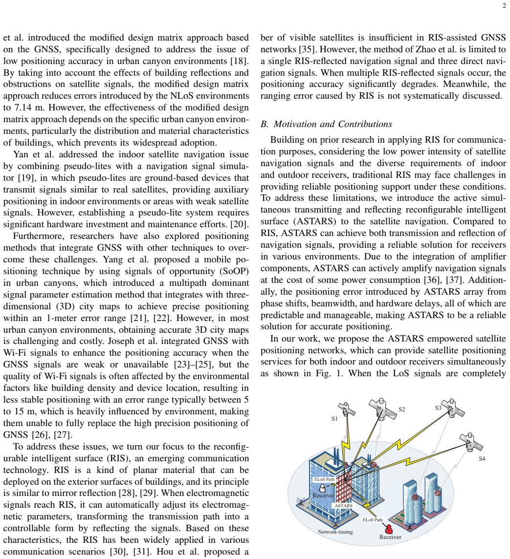
The paper's central claim is that an ASTARS relay creates a usable positioning geometry for a standard GNSS receiver even when no satellite is directly visible: the receiver observes carrier phase from each satellite through the ASTARS, estimates the ASTARS position and the ASTARS-to-receiver propagation time from those observations using least squares, then uses angle-of-arrival and angle-of-departure broadcasts to correct each relayed path into the true satellite-receiver distance. With network timing that pins the receiver clock bias to within 10 ns, simulations show indoor and urban-canyon receivers achieve positioning errors within 4 m, with the method's newly introduced errors (phase shift, beamwidth, timing, satellite geometry) within 3 m.
Load-bearing premise
The receiver can synchronize to network time within about 10 nanoseconds in the very urban-canyon and indoor environments where GNSS signals are blocked, so that the receiver clock bias is known well enough to separate it from the ASTARS-to-receiver travel time.
Editorial extensions
If this is right
- If network time synchronization stays within 10 ns and the ASTARS can view at least five satellites, both indoor and urban-canyon receivers get positioning errors at most 4 m in simulation.
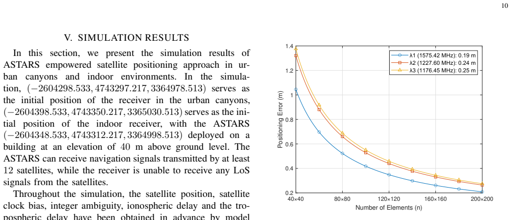
- Increasing the number of relayed satellites from 5 to 12 lowers the ASTARS position RMSE from about 1.6 m to 0.5 m, with error fluctuation shrinking to within 0.05 m.
- The method's newly introduced errors (phase shift, beamwidth, time synchronization, and satellite geometry) stay within 3 m at 10 ns timing error, which is better than the 5 m typical of conventional NLoS methods.
- The approach depends on network timing infrastructure that the paper argues is already plausible, citing 5G/6G synchronization requirements and demonstrated sub-5 ns timing accuracy.
- Because the relayed signal keeps the original navigation data, PRN code, and carrier, existing GNSS receivers can be used without hardware or signal-structure changes.
Reading between the lines
- If real deployments cannot hold 10 ns synchronization inside deep urban canyons and buildings, the claimed 4 m bound degrades by roughly 0.3 m per nanosecond of timing error, so the approach's practical reach is set by network timing infrastructure availability.
- The same ELoS correction logic could apply to low-Earth-orbit (LEO) navigation signals, which the paper names as a future direction; LEO's stronger signals could relax the ASTARS amplification requirement.
- The two-step least-squares design trades satellite count for reliance on AoA/AoD broadcasts, so the 4 m claim implicitly depends on the MUSIC angle error model and beamwidth assumptions holding in real urban scattering environments.
- If ASTARS arrays serve both communication and positioning in a 6G deployment, the marginal cost of adding positioning could be low, but the paper does not quantify that sharing trade-off.
Editorial analysis
A structured set of objections, weighed in public.
Referee Report
Summary. This paper proposes an ASTARS-aided GNSS positioning scheme for receivers in urban canyons and indoor environments. The ASTARS reflects or transmits satellite signals over an extended line-of-sight (ELoS) path; the receiver uses network time synchronization to separate the ELoS delay from its clock bias, estimates the ASTARS position from carrier-phase observations via iterative least squares, corrects the satellite-to-receiver range using a triangle formed with AoA/AoD information, and then solves for its own position. The paper claims positioning errors not exceeding 4 m with 10 ns network synchronization and an additional-error bound of 3 m, supported by Monte Carlo simulations.
Significance. The system concept is timely and the paper offers a clearly structured ELoS observation model, an explicit error taxonomy, and a comparative simulation study. If the headline accuracy were reproducible, the approach would be a meaningful alternative for GNSS-denied environments. Credit is due for the explicit modeling of the ELoS path and for the systematic decomposition of error sources in Section IV. However, the two load-bearing pillars—the correctness of the iterative LS formulation and the ambiguity-resolution mechanism—are not established, and the principal 'additional error' claim is essentially a restatement of c·γ. Because these issues affect the central claims and cannot be resolved by local editing, the paper in its current form does not support its stated contributions.
major comments (3)
- [III-A, Eqs. (14) and (17)-(18)] The Taylor expansion in Eq. (14) has the sign of the geometric partial derivatives reversed. For r_i = |X_i - X_R|, the derivative of r_i with respect to X_R is (X_R - X_i)/r_i, not (X_i - X_R)/r_i. With Δx = x_R - x_0, the correct coefficient is (x_0 - x_i)/r_i. As written, the least-squares update in Eqs. (17)-(18) moves the ASTARS estimate in the opposite direction from the residual, so the iterative scheme cannot converge to the ASTARS position. This is a central error in the proposed positioning pipeline.
- [III-A, Algorithm 1; V, simulation setup] The carrier-phase observation set (13) contains an integer ambiguity N_i per satellite. The only ambiguity-resolution method given is Algorithm 1, an RTK double-difference procedure that requires a base station with known coordinates, synchronous observations of the same satellites, and a data link to the rover. Neither the system model in Section II nor the simulation setup in Section V defines such a base station; Section V states that the integer ambiguity, satellite clock bias, and ionospheric/tropospheric delays are 'obtained in advance by model calculations.' The receiver positioning results in Figs. 12-13 therefore assume that the critical ambiguity-resolution step is already solved. Without fixing the N_i, the system (13)-(18) has one extra integer unknown per satellite and is underdetermined, so no concrete configuration of the proposed method can be instantiated to reproduce the headline ≤4 m accuracy.
- [V-A.2, Eq. (33), Abstract] The second headline result—'additional errors do not exceed 3 m for time synchronization errors within 10 ns'—is a restatement of Eq. (33), Δd ≈ c·γ, since c·10 ns = 3 m. Figure 7 plots exactly this linear relation; the result contains no composite modeling of the other error sources listed in the abstract. Table II, moreover, lists the network time synchronization error range as 2-30 m, which is inconsistent with using 3 m as a universal bound. The claim as stated is therefore circular rather than a derived performance bound.
minor comments (5)
- [II.C, Eqs. (9) and (13)] Equation (9) omits the integer ambiguity term after stating that LAMBDA resolves it, but Eq. (13) reintroduces +N_iλ without explaining whether the ambiguity is subtracted from the observation or estimated; this inconsistency should be clarified.
- [III-A, Eq. (14) and Table I] Table I defines r_{i,Rs} and r_{Ru}, but Eq. (14) uses r_i without defining it as r_{i,Rs}; please align the notation consistently throughout Section III.
- [V-B, Fig. 11] The RMSE curves in Fig. 11 show variability, but no confidence intervals or standard deviations are reported; given the Monte Carlo setup, reporting mean ± std would strengthen the comparison.
- [IV.E, Eq. (37)] The total error ω in Eq. (37) mixes phase shift (θA_k λ/2π), beamwidth (Δp), timing (cγ), and DoP-scaled measurement noise (σ_position DoP); the derivation of this additive combination is not given, so it should be stated as an approximate budget rather than an exact formula.
- [V-A, Fig. 8 caption] The caption contains a typo ('reflction' instead of 'reflection'); also, Figs. 12 and 13 would benefit from error bars or shading to show dispersion across Monte Carlo runs.
Circularity Check
One headline error bound is a definitional unit conversion; the main positioning pipeline is not circular.
-
self definitional
[Abstract (bullet 2); Section IV-C, Eq. (33); Section V-A.2]
"the additional errors introduced by the proposed method do not exceed 3 m for time synchronization errors within 10 ns ... Thus, the network time synchronization error ∆d is calculated as: ∆d ≈ c · γ. (33) ... Results indicate that when timing accuracy is controlled at 10 ns, the distance error is 3 m."
The claimed 3 m bound is not an independent prediction from the positioning pipeline; it is the definitional conversion of the input timing error. Equation (33) defines the distance error as Δd = c·γ, and inserting γ = 10 ns gives c·10 ns ≈ 3 m exactly. The simulation subsection then reports that same arithmetic ('when timing accuracy is controlled at 10 ns, the distance error is 3 m') as a result. The abstract presents this as a finding that 'includes the phase shift, beamwidth error, time synchronization errors, and satellite distribution errors,' but the 3 m figure is saturated by the timing term alone and is true by construction. No simulation or estimation step is needed to obtain it; the result is equivalent to its own input.
full rationale
The core positioning derivation is not circular. The receiver forms carrier-phase observations of ASTARS-relayed satellite signals; Eq. (13) models them as satellite-ASTARS distance minus the combined clock/ELoS term plus integer ambiguities. Section III-A solves for ASTARS coordinates and the combined temporal term by least squares (Eqs. (14)-(18)); network time synchronization then separates the ELoS propagation time (Eq. (19)), giving r_Ru = c·T_R_hat (Eq. (20)); the triangle correction (Eqs. (21)-(22)) converts relayed ranges to satellite-receiver ranges using broadcast AoA/AoD; and a second least-squares fit yields the receiver position. Each step uses independently modeled geometry, and no step is defined in terms of the final receiver position. The 4 m positioning accuracy is a Monte Carlo result with assumed error distributions, not a restatement of an input. The only definitional sub-claim is the second headline result: 'additional errors do not exceed 3 m for time synchronization errors within 10 ns' is exactly Eq. (33), Δd ≈ cγ, evaluated at γ = 10 ns, i.e., a unit conversion. Separately, Section V states that 'the integer ambiguity ... [is] obtained in advance by model calculations' while Algorithm 1 requires an RTK base station that is never defined; this is an internal implementation gap, not a circular reduction, so it is not counted in the score. Self-citations (e.g., [32], [33], [35]) motivate ASTARS but are not load-bearing in the positioning derivation, and no uniqueness theorem is imported from prior work.
Assumptions & free parameters
free parameters (5)
- ASTARS element spacing L =
0.125 m (lambda_max/2)
- Number of ASTARS elements per row e =
40 (plus 40x40 to 200x200 in beamwidth study)
- Network time synchronization error gamma =
1 to 10 ns in the claimed regime
- Measurement rate f =
500 Hz in final results
- Standard deviation of timing measurements upsilon =
1e-4 s
assumptions (5)
- domain assumption 10 ns network time synchronization is available to the indoor/urban receiver and its clock bias error gamma is the residual after sync.
- domain assumption Integer ambiguities are fixed before ASTARS positioning via RTK DD-AR with an available base station.
- domain assumption AoA and AoD of each satellite signal are known to the receiver through the ASTARS beacon, with MUSIC AoA error variance 6/(rho_s L_s K(K^2-1)).
- ad hoc to paper ASTARS hardware delay is negligible and phase-shift error is bounded by 1-3 wavelengths.
- domain assumption ELoS small-scale fading follows Rayleigh and satellite-ASTARS fading follows Rician.
Cite this review
Pith. "Pith review of ASTARS empowered Satellite Positioning Approach for Urban Canyons and Indoor Environments." pith.science (2026). https://pith.science/paper/TQNXGN33
@misc{pith2026250701783,
  author       = {Pith},
  title        = {Pith review of: ASTARS empowered Satellite Positioning Approach for Urban Canyons and Indoor Environments},
  year         = {2026},
  howpublished = {\url{https://pith.science/paper/TQNXGN33}},
  note         = {Machine review of arXiv:2507.01783}
}
read the original abstract
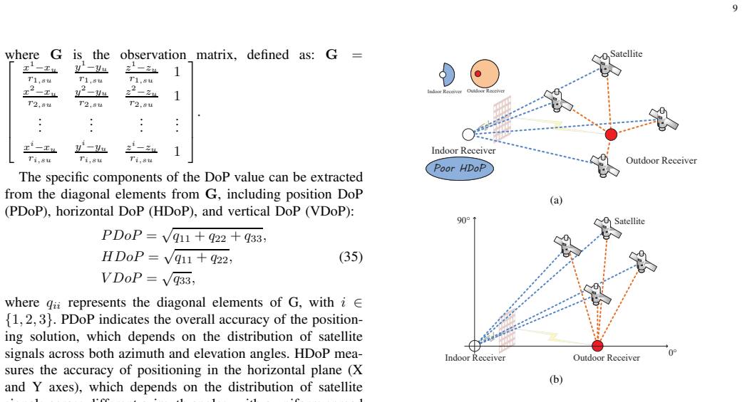
To mitigate the loss of satellite navigation signals in urban canyons and indoor environments, we propose an active simultaneous transmitting and reflecting reconfigurable intelligent surface (ASTARS) empowered satellite positioning approach. Deployed on building structures, ASTARS reflects navigation signals to outdoor receivers in urban canyons and transmits signals indoors to bypass obstructions, providing high-precision positioning services to receivers in non-line-of-sight (NLoS) areas. The path between ASTARS and the receiver is defined as the extended line-of-sight (ELoS) path and an improved carrier phase observation equation is derived to accommodate that. The receiver compensates for its clock bias through network time synchronization, corrects the actual signal path distance to the satellite-to-receiver distance through a distance correction algorithm, and determines its position by using the least squares (LS) method. Mathematical modeling of the errors introduced by the proposed method is conducted, followed by simulation analysis to assess their impact. Simulation results show that: 1) in areas where GNSS signals are blocked, with time synchronization accuracy within a 10 ns error range, the proposed method provides positioning services with errors not exceeding 4 m for both indoor and outdoor receivers, outperforming conventional NLoS methods with positioning errors of more than 7 m; 2) the additional errors introduced by the proposed method do not exceed 3 m for time synchronization errors within 10 ns, which includes the phase shift, beamwidth error, time synchronization errors, and satellite distribution errors, outperforming traditional NLoS methods, which typically produce positioning errors greater than 5 m.
Figures


Figures from the paper (8 more)



Reference graph
Works this paper leans on
-
[1]
GNSS P osition Integrity in Urban Environments: A Review of Literature,
N. Zhu, J. Marais, D. B´ etaille, and M. Berbineau, “GNSS P osition Integrity in Urban Environments: A Review of Literature,” IEEE Trans. Intell. Transp. Syst. , vol. 19, no. 9, pp. 2762–2778, Jan. 2018
work page 2018
-
[2]
J. Wickert, E. Cardellach, M. Mart´ ın-Neira, J. Bandeir as, Bertinoaz et al. , “GEROS-ISS: GNSS REflectometry, Radio Occultation, and Scatterometry Onboard the International Space Station,” IEEE J. Sel. Top. Appl. Earth Obs. Remote Sens. , vol. 9, no. 10, pp. 4552–4581, Oct. 2016
work page 2016
-
[3]
GDOP-based analysis of suitability of LEO constellations for future sa tellite-based positioning,
R. Morales-Ferre, E. S. Lohan, G. Falco, and E. Falletti, “GDOP-based analysis of suitability of LEO constellations for future sa tellite-based positioning,” in 2020 IEEE Int. Conf. Wireless Space Extreme Environ. (WiSEE), 2020, pp. 147–152
work page 2020
-
[4]
Analysis of GDOP based on GEO satellite,
S. Kartal, Y . B. Kaya, F. Nergiz, E. ¨Ozba˘ g, Y . Yilmaz, and T. Dar, “Analysis of GDOP based on GEO satellite,” in 2023 10th Int. Conf. Recent Adv. Air Space Technol. (RAST) , 2023, pp. 1–5
work page 2023
-
[5]
A Vision of 6G Wireless Sy stems: Applications, Trends, Technologies, and Open Research Pro blems,
W. Saad, M. Bennis, and M. Chen, “A Vision of 6G Wireless Sy stems: Applications, Trends, Technologies, and Open Research Pro blems,” IEEE Netw., vol. 34, no. 3, pp. 134–142, Feb. 2020
work page 2020
-
[6]
6G Wireless Networks: Vision, Requirements, Ar chitecture, and Key Technologies,
Z. Zhang, Y . Xiao, Z. Ma, M. Xiao, Z. Ding, X. Lei, G. K. Kara giannidis, and P . Fan, “6G Wireless Networks: Vision, Requirements, Ar chitecture, and Key Technologies,” IEEE V eh. Technol. Mag. , vol. 14, no. 3, pp. 28–41, Sep. 2019
work page 2019
-
[7]
Research on 5G High P recision Time Synchronous Networking Scheme,
D. Qing, Z. Hongxiang, and Y . Lijun, “Research on 5G High P recision Time Synchronous Networking Scheme,” in 2021 IEEE 3rd Interna- tional Conference on Civil Aviation Safety and Information Technology (ICCASIT), 2021, pp. 1020–1024
work page 2021
-
[8]
GNSS Vulnerabilities and Existing Solutions: A R eview of the Literature,
J. Zidan, E. I. Adegoke, E. Kampert, S. A. Birrell, C. R. Fo rd, and M. D. Higgins, “GNSS Vulnerabilities and Existing Solutions: A R eview of the Literature,” IEEE Access , vol. 9, pp. 153 960–153 976, Feb. 2021
work page 2021
Show all 54 references
-
[9]
Positioning Perfo rmance of LEO Mega Constellations in Deep Urban Canyon Environments,
H. More, E. Cianca, and M. De Sanctis, “Positioning Perfo rmance of LEO Mega Constellations in Deep Urban Canyon Environments, ” in 2022 25th Int. Symp. Wireless Personal Multimedia Commun. ( WPMC), 2022, pp. 256–260
2022
-
[10]
GPS Multipath and NLOS Mitig ation for Relative Positioning in Urban Environments,
Y . Y uan, F. Shen, and X. Li, “GPS Multipath and NLOS Mitig ation for Relative Positioning in Urban Environments,” Aerosp. Sci. Technol., vol. 107, pp. 106 315–106 325, Jun. 2020
2020
-
[11]
Comparing Positi oning Per- formance of LEO Mega-Constellations and GNSS in Urban Canyo ns,
H. More, E. Cianca, and M. De Sanctis, “Comparing Positi oning Per- formance of LEO Mega-Constellations and GNSS in Urban Canyo ns,” IEEE Access , vol. 12, pp. 24 465–24 482, Oct. 2024
2024
-
[12]
Posi- tion, Navigation, and Timing (PNT) Through Low Earth Orbit ( LEO) Satellites: A Survey on Current Status, Challenges, and Opp ortunities,
F. S. Prol, R. M. Ferre, Z. Saleem, P . V¨ alisuo, C. Pinell et al. , “Posi- tion, Navigation, and Timing (PNT) Through Low Earth Orbit ( LEO) Satellites: A Survey on Current Status, Challenges, and Opp ortunities,” IEEE Access , vol. 10, pp. 83 971–84 002, Jul. 2022
2022
-
[13]
Recent Advances in Indoor Lo cal- ization: A Survey on Theoretical Approaches and Applicatio ns,
A. Y assin, Y . Nasser, M. Awad, A. Al-Dubai, R. Liu, C. Y ue n, R. Raulefs, and E. Aboutanios, “Recent Advances in Indoor Lo cal- ization: A Survey on Theoretical Approaches and Applicatio ns,” IEEE Commun. Surv. Tutor ., vol. 19, no. 2, pp. 1327–1346, Nov. 2017
2017
-
[14]
Estimation and Ex clusion of Multipath Range Error for Robust Positioning,
T. Iwase, N. Suzuki, and Y . Watanabe, “Estimation and Ex clusion of Multipath Range Error for Robust Positioning,” GPS Solut. , vol. 17, no. 1, p. 53–62, Jan. 2013
2013
-
[15]
Height Aiding, C/N0 Weightin g and Consistency Checking for GNSS NLOS and Multipath Mitigatio n in Urban Areas,
P . D. Groves and Z. Jiang, “Height Aiding, C/N0 Weightin g and Consistency Checking for GNSS NLOS and Multipath Mitigatio n in Urban Areas,” J. Navig., vol. 66, pp. 653 – 669, Jul. 2013
2013
-
[16]
Fast Multiple Faul t Exclusion with a Large Number of Measurements,
J. Blanch, T. Walter, and P . K. Enge, “Fast Multiple Faul t Exclusion with a Large Number of Measurements,” in Proceedings of the 2015 International Technical Meeting of The Institute of Naviga tion.(ION), Jan. 2015, pp. 1–6
2015
-
[17]
Multipl e Faulty GNSS Measurement Exclusion Based on Consistency Check in Ur ban Canyons,
L. Hsu, H. Tokura, N. Kubo, Y . Gu, and S. Kamijo, “Multipl e Faulty GNSS Measurement Exclusion Based on Consistency Check in Ur ban Canyons,” IEEE Sens. J. , vol. 17, pp. 1909–1917, Mar. 2017
1909
-
[18]
En hancing GNSS Positioning in Urban Canyon Areas via a Modified Design M atrix Approach,
W. Chen, C. Zhang, Y . Peng, Y . Y ao, M. Cai, and D. Dong, “En hancing GNSS Positioning in Urban Canyon Areas via a Modified Design M atrix Approach,” IEEE Internet Things J. , vol. 11, no. 6, pp. 10 252–10 265, Oct. 2024
2024
-
[19]
Inter-satellite Pseudorange Diffe rence Indoor Positioning Using Simulator Pseudolites,
F. Y an and M. Song, “Inter-satellite Pseudorange Diffe rence Indoor Positioning Using Simulator Pseudolites,” in 2022 International Com- munication Engineering and Cloud Computing Conference (CE CCC), 2022, pp. 37–41
2022
-
[20]
Indoor combin ation positioning technology of Pseudolites and PDR,
X. Gan, B. Y u, Z. Heng, L. Huang, and Y . Li, “Indoor combin ation positioning technology of Pseudolites and PDR,” in 2018 Ubiquitous Po- sitioning, Indoor Navigation and Location-Based Services (UPINLBS), 2018, pp. 1–7
2018
-
[21]
Mobile Positioning with Signa ls of Oppor- tunity in Urban and Urban Canyon Environments,
C. Y ang and A. Soloviev, “Mobile Positioning with Signa ls of Oppor- tunity in Urban and Urban Canyon Environments,” in 2020 IEEE/ION Position, Location Navig. Symp. (PLANS) , 2020, pp. 1043–1059
2020
-
[22]
GNSS-5G Hybrid Positioning Based on Multi-Rate Measureme nts Fusion and Proactive Measurement Uncertainty Prediction,
L. Bai, C. Sun, A. G. Dempster, H. Zhao, J. W. Cheong, and W . Feng, “GNSS-5G Hybrid Positioning Based on Multi-Rate Measureme nts Fusion and Proactive Measurement Uncertainty Prediction,” IEEE Trans. Instrum. Meas. , vol. 71, pp. 1–15, Feb. 2022. 14 TABLE III: Comparison of p...
2022
-
[23]
GNSS Feature Map Aided RTK Pos itioning in Urban Trenches,
F. Ruwisch and S. Sch¨ on, “GNSS Feature Map Aided RTK Pos itioning in Urban Trenches,” in 2023 IEEE 26th Int. Conf. Intelligent Transp. Syst. (ITSC) , 2023, pp. 5798–5804
2023
-
[24]
Analysis of INS Parameters and Erro r Reduction by Integrating GPS and INS Signals,
D. M.G. and A. Arun, “Analysis of INS Parameters and Erro r Reduction by Integrating GPS and INS Signals,” in 2018 Int. Conf. Design Innov. 3Cs Compute Commun. Control (ICDI3C) , 2018, pp. 18–23
2018
-
[25]
Indoor positioning sy stem techniques and security,
S. Kim, S. Ha, A. Saad, and J. Kim, “Indoor positioning sy stem techniques and security,” in 2015 F orth International Conference on e-Technologies and Networks for Development (ICeND) , 2015, pp. 1–4
2015
-
[26]
Indoor Positioning Using WiFi Fingerprint,
R. Joseph and S. B. Sasi, “Indoor Positioning Using WiFi Fingerprint,” in 2018 Int. Conf. Circuits Syst. Digital Enterp. Technol. (IC CSDET), 2018, pp. 1–3
2018
-
[27]
Demand-Aware Flexible Handover Strategy for LEO Cons tella- tion,
T. S. Abdu, E. Lagunas, V . N. Ha, J. Grotz, S. Kisseleff, a nd S. Chatzino- tas, “Demand-Aware Flexible Handover Strategy for LEO Cons tella- tion,” in 2023 IEEE Int. Conf. Commun. W orkshops (ICC W orkshops) , 2023, pp. 978–983
2023
-
[28]
Reconfigurable Intelligent Surfaces: Principles and Opportu- nities,
Y . Liu, X. Liu, X. Mu, T. Hou, J. Xu, M. Di Renzo, and N. Al- Dhahir, “Reconfigurable Intelligent Surfaces: Principles and Opportu- nities,” IEEE Commun. Surv. Tutorials , vol. 23, no. 3, pp. 1546–1577, May 2021
2021
-
[29]
STAR-RISs: Simulta neous Transmitting and Reflecting Reconfigurable Intelligent Sur faces,
J. Xu, Y . Liu, X. Mu, and O. A. Dobre, “STAR-RISs: Simulta neous Transmitting and Reflecting Reconfigurable Intelligent Sur faces,” IEEE Commun. Lett. , vol. 25, no. 9, pp. 3134–3138, May 2021
2021
-
[30]
Smart Radio Environments Emp owered by Reconfigurable Intelligent Surfaces: How It Works, State of Research, and The Road Ahead,
M. Di Renzo, A. Zappone, M. Debbah, M.-S. Alouini, C. Y ue n, J. de Rosny, and S. Tretyakov, “Smart Radio Environments Emp owered by Reconfigurable Intelligent Surfaces: How It Works, State of Research, and The Road Ahead,” IEEE J. Sel. Areas Commun. , vol. 38, no. 11, pp. 2450...
2020
-
[31]
Rec onfig- urable Intelligent Surface Aided NOMA Networks,
T. Hou, Y . Liu, Z. Song, X. Sun, Y . Chen, and L. Hanzo, “Rec onfig- urable Intelligent Surface Aided NOMA Networks,” IEEE J. Sel. Areas Commun., vol. 38, no. 11, pp. 2575–2588, Nov. 2020
2020
-
[32]
Performance Analysis of NOMA-RIS Aide d Inte- grated Navigation and Communication (INAC) Networks,
T. Hou and A. Li, “Performance Analysis of NOMA-RIS Aide d Inte- grated Navigation and Communication (INAC) Networks,” IEEE Trans. V eh. Technol., vol. 72, no. 10, pp. 13 255–13 268, May 2023
2023
-
[33]
Integra ted Navigation and Communication (INAC) Networks: A NOMA-RIS a ided Approach,
A. Li, T. Hou, J. Gao, J. Wang, X. Xu, and Z. Song, “Integra ted Navigation and Communication (INAC) Networks: A NOMA-RIS a ided Approach,” in 2023 IEEE 23rd International Conference on Communi- cation Technology (ICCT) , 2023, pp. 1596–1601
2023
-
[34]
RIS-NOMA-aided LEO Satellite Communication Networks,
D. Guan, X. Sun, J. Wang, and T. Hou, “RIS-NOMA-aided LEO Satellite Communication Networks,” in 2022 10th Int. Conf. Inf. Syst. Comput. Technol. (ISCTech), 2022, pp. 409–413
2022
-
[35]
I ntegrated- Navigation-and-Communication (INAC): A Reconfigurable In telligent Surface (RIS)-aided Approach,
Q. Zhao, W. Gong, T. Hou, X. Sun, A. Li, and E. Bodanese, “I ntegrated- Navigation-and-Communication (INAC): A Reconfigurable In telligent Surface (RIS)-aided Approach,” in 2023 IEEE VTC Spring , 2023, pp. 1–6
2023
-
[36]
Active RIS vs. Passive RIS: Which Will Prevail in 6G?
Z. Zhang, L. Dai, X. Chen, C. Liu, F. Y ang, R. Schober, and H. V . Poor, “Active RIS vs. Passive RIS: Which Will Prevail in 6G?” IEEE Trans. Commun., vol. 71, no. 3, pp. 1707–1725, Dec. 2023
2023
-
[37]
Acti ve RIS V ersus Passive RIS: Which is Superior With the Same Power Bud get?
K. Zhi, C. Pan, H. Ren, K. K. Chai, and M. Elkashlan, “Acti ve RIS V ersus Passive RIS: Which is Superior With the Same Power Bud get?” IEEE Commun. Lett. , vol. 26, no. 5, pp. 1150–1154, Mar. 2022
2022
-
[38]
High-reliability sub- nanosecond network time synchronization method enabled by double- frequency distributed time synchronization,
R. Luo, N. Hua, X. Zheng, and B. Zhou, “High-reliability sub- nanosecond network time synchronization method enabled by double- frequency distributed time synchronization,” J. Opt. Commun. Netw. , vol. 11, no. 1, pp. A40–A51, Feb. 2019
2019
-
[39]
More robust high precision time synchronization system,
H. Cao, J. Shen, R. Y an, Y . Zhao, W. Xu, and L. Geng, “More robust high precision time synchronization system,” in 2024 IEEE Int. Symp. Precision Clock Synchronization for Measurement, Co ntrol, and Communication (ISPCS) , Nov. 2024, pp. 1–6
2024
-
[40]
IEEE 1588 for Clock Synchronization in Industria l IoT and Related Applications: A Review on Contributing Technol ogies, Protocols and Enhancement Methodologies,
Z. Idrees, J. Granados, Y . Sun, S. Latif, L. Gong, Z. Zou, and L. Zheng, “IEEE 1588 for Clock Synchronization in Industria l IoT and Related Applications: A Review on Contributing Technol ogies, Protocols and Enhancement Methodologies,” IEEE Access , vol. 8, pp. 155 660–155 6...
2020
-
[41]
A Satellite-Ground Precise Time Synchronization Method and Analysis on Time Delay Error Caused by Motion,
Y . Guo, Y . Bai, S. Gao, Z. Pan, Z. Han, Y . Gao, and X. Lu, “A Satellite-Ground Precise Time Synchronization Method and Analysis on Time Delay Error Caused by Motion,” in China Satellite Navigation Conference (CSNC 2021) Proceedings , Jun. 2021
2021
-
[42]
The Field Equivale nce Principle: Illustration of the Establishment of the Non-intuitive Nul l Fields,
S. Rengarajan and Y . Rahmat-Samii, “The Field Equivale nce Principle: Illustration of the Establishment of the Non-intuitive Nul l Fields,” IEEE Antennas Propag. Mag. , vol. 42, no. 4, pp. 122–128, Aug. 2000
2000
-
[43]
M. Born, E. Wolf, A. B. Bhatia, P . C. Clemmow, D. Gabor, A. R. Stokes, A. M. Taylor, P . A. Wayman, and W. L. Wilcock, Principles of Optics: Electromagnetic Theory of Propagation, Interference and D iffraction of Light, 7th ed. Cambridge University Press, 1999
1999
-
[44]
Multiple emitter location and signal para meter estimation,
R. Schmidt, “Multiple emitter location and signal para meter estimation,” IEEE Trans. Antennas Propag. , vol. 34, no. 3, pp. 276–280, Mar. 1986
1986
-
[45]
Demonstration of Millimeter-Wave Reconfigurable Intelli gent Surface (RIS) With Built-In Sensors for Automatic Tracking of Direc tion-of- Arrival (DOA),
M. Hwang, D. An, S. Chang, Y . Y oun, D. Kim, C. Lee, and W. Ho ng, “Demonstration of Millimeter-Wave Reconfigurable Intelli gent Surface (RIS) With Built-In Sensors for Automatic Tracking of Direc tion-of- Arrival (DOA),” IEEE Sens. Lett. , vol. 7, no. 8, pp. 1–4, Jul. 2023
2023
-
[46]
En hancing Urban Mobile Communications with Dynamic 3D Beam Tracking: A 2-Bit Phase-Quantized Adaptive RIS Approach,
Y . Zhao, X. Ma, Z. Wang, Y . Liu, C. Y uen, and Y . L. Guan, “En hancing Urban Mobile Communications with Dynamic 3D Beam Tracking: A 2-Bit Phase-Quantized Adaptive RIS Approach,” in 2024 IEEE 35th International Symposium on Personal, Indoor and Mobil e Radio Communications (...
2024
-
[47]
Hofmann-Wellenhof, H
B. Hofmann-Wellenhof, H. Lichtenegger, and J. Collins , Global Posi- tioning System: Theory and Practice . Springer Science & Business Media, 2012
2012
-
[48]
Phase Noise Mo deling and Experimental Demonstration of Single and Dual-Loop Dir ect Mod- ulation Optoelectronic Oscillator,
H. Y erranna, K. S. Kumar, and S. L. Sabat, “Phase Noise Mo deling and Experimental Demonstration of Single and Dual-Loop Dir ect Mod- ulation Optoelectronic Oscillator,” IEEE J. Quantum Electron. , vol. 58, no. 6, pp. 1–10, Oct. 2022
2022
-
[49]
GNSS Multipath Er ror Modeling and Mitigation by Using Sparsity-Promoting Regul arization,
C. Chen, G. Chang, N. Zheng, and T. Xu, “GNSS Multipath Er ror Modeling and Mitigation by Using Sparsity-Promoting Regul arization,” IEEE Access , vol. 7, pp. 24 096–24 108, Feb 2019
2019
-
[50]
The Least-Squares Ambiguity Decor relation Ad- justment: A Method for Fast GPS Integer Ambiguity Estimatio n ,
P . J. G. Teunissen, “The Least-Squares Ambiguity Decor relation Ad- justment: A Method for Fast GPS Integer Ambiguity Estimatio n ,” J. Geodesy, vol. 70, no. 1, pp. 65–82, Nov. 1995
1995
-
[51]
Ionospheric Time-Delay Algorithm fo r Single- Frequency GPS Users,
J. A. Klobuchar, “Ionospheric Time-Delay Algorithm fo r Single- Frequency GPS Users,” IEEE Trans. Aerosp. Electron. Syst. , vol. AES- 23, no. 3, pp. 325–331, May 1987
1987
-
[52]
Atmospheric correction for the trop osphere and strato- sphere in radio ranging satellites,
J. Saastamoinen, “Atmospheric correction for the trop osphere and strato- sphere in radio ranging satellites,” Geophys. Monogr . Ser ., Mar. 1972
1972
-
[53]
On the interoperability of IGS products for precise point p ositioning with ambiguity resolution,
S. Banville, J. Geng, S. Loyer, S. Schaer, T. Springer, a nd S. Strasser, “On the interoperability of IGS products for precise point p ositioning with ambiguity resolution,” J. Geodesy , vol. 94, no. 1, pp. 10–25, Jan. 2020
2020
-
[54]
A Comprehensive Systematic Review of Integrati on of Time Sensitive Networking and 5G Communication,
Z. Satka, M. Ashjaei, H. Fotouhi, M. Daneshtalab, M. Sj¨ odin, and S. Mubeen, “A Comprehensive Systematic Review of Integrati on of Time Sensitive Networking and 5G Communication,” J. Syst. Archit. , vol. 138, pp. 102 852–102 874, May 2023
2023
Reviewed August 6, 2026 · model on record in the stance chip above.
Discussion (0). Sign in to comment.