Optimization-Based Velocity-Integral Sliding-Window Coarse Alignment: Attitude Error Analysis and Validation
Pith reviewed 2026-06-25 20:11 UTC · model grok-4.3
The pith
A first-order error propagation model maps sensor uncertainties to attitude misalignment in sliding-window velocity-integral OBA.
A machine-rendered reading of the paper's core claim, the machinery that carries it, and where it could break.
Core claim
The paper claims that the first-order model, built from the discrete sliding-window observation model and Davenport's q-method, accurately captures deterministic attitude offsets caused by systematic errors and precisely characterizes the statistical spread of attitude errors arising from stochastic noise, with the derived covariances reliably bounding the actual errors.
What carries the argument
First-order attitude error propagation model that analytically maps perturbations in non-normalized observation vectors, obtained from the sliding-window velocity-integral model, to attitude misalignment via Davenport's q-method.
Load-bearing premise
The first-order linearization and decoupling of systematic errors from stochastic noise remain valid when the gyroscope, accelerometer, GNSS velocity, and lever-arm uncertainties are propagated through the sliding-window observation model.
What would settle it
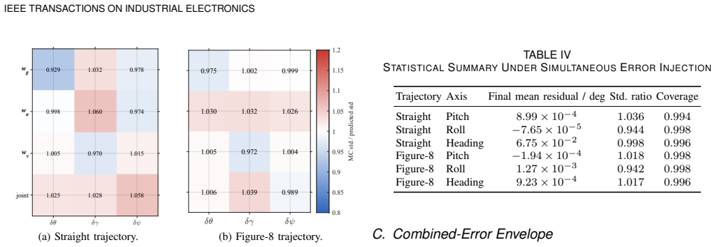
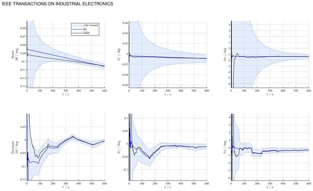
Monte Carlo simulations in which the ratio of analytical to empirical standard deviations falls outside 0.929-1.060 or the empirical coverage drops below 99.4 percent, or vehicle tests in which the predicted covariance envelopes fail to bound the measured attitude errors.
Figures
read the original abstract
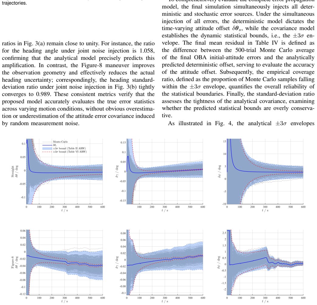
The optimization-based alignment (OBA) approach transforms the strapdown inertial navigation system (SINS) coarse alignment into a constant initial attitude estimation problem, serving as a prevalent technique for global navigation satellite system (GNSS)-aided in-motion alignment. While existing studies focus on improving accuracy by refining attitude determination algorithms or constructing robust observation vectors, a rigorous analytical mapping to evaluate the resulting attitude errors from raw sensor and aiding-velocity uncertainties has yet to be established for fixed-length sliding-window velocity-integral OBA. To address this issue, this paper proposes a first-order attitude error propagation model for GNSS-aided sliding-window velocity-integral OBA. Specifically, a sliding-window observation model and its discrete implementation are formulated, through which gyroscope errors, accelerometer errors, GNSS velocity noise, and lever-arm effects are analytically propagated to non-normalized observation vectors. Subsequently, Davenport's q method is used to establish the mapping from these vector perturbations to attitude misalignment. By decoupling systematic errors and stochastic noise, the deterministic attitude offsets and the attitude error covariances are respectively derived. Monte Carlo simulations demonstrate that the analytical model accurately captures the deterministic attitude offsets and precisely characterizes the statistical spread, yielding standard-deviation ratios between 0.929 and 1.060 with empirical coverage above 99.4%. Vehicle field tests further confirm its practical applicability, showing that the predicted covariance envelopes reliably bound the actual initial-attitude errors, with steady-state RMSEs strictly below 0.00495 deg. These results validate the proposed model for coarse-alignment attitude error assessment.
Editorial analysis
A structured set of objections, weighed in public.
Referee Report
Summary. The paper claims to develop a first-order attitude error propagation model for GNSS-aided sliding-window velocity-integral optimization-based alignment (OBA) in strapdown inertial navigation systems. It formulates a sliding-window observation model, analytically propagates errors from gyroscopes, accelerometers, GNSS velocity, and lever-arm effects to non-normalized observation vectors, applies Davenport's q-method to map these to attitude misalignment, derives deterministic offsets and stochastic covariances by decoupling systematic and random errors, and validates the model through Monte Carlo simulations (std-dev ratios 0.929-1.060, coverage >99.4%) and vehicle field tests (RMSE <0.00495 deg).
Significance. If the first-order model holds in the tested regimes, the work supplies a useful analytical tool for predicting attitude errors in OBA coarse alignment, reducing reliance on purely empirical methods. The explicit propagation of multiple error sources through the observation model and q-method, together with the decoupling of deterministic offsets from covariances, is a clear strength; the close match between predicted and observed statistics in both Monte Carlo runs and field tests further supports its utility for system analysis and design in GNSS-aided inertial navigation.
minor comments (2)
- [Abstract] Abstract: the reported RMSE bound of 0.00495 deg would be clearer if the corresponding time window, vehicle dynamics, and GNSS conditions were briefly indicated to allow readers to assess the operating regime.
- [Validation sections] The manuscript would benefit from an explicit statement of the range of error magnitudes (e.g., gyro bias, velocity noise) over which the first-order approximation was verified to remain accurate, even if only in the validation sections.
Simulated Author's Rebuttal
We thank the referee for the positive assessment of the manuscript, the clear summary of its contributions, and the recommendation for minor revision. No major comments appear in the report.
Circularity Check
No circularity: standard first-principles error propagation via observation model and Davenport q-method
full rationale
The derivation formulates a sliding-window observation model, analytically propagates sensor and aiding errors (gyro, accel, GNSS velocity, lever-arm) to non-normalized vectors, applies Davenport's q-method for attitude mapping, and decouples systematic vs. stochastic terms to obtain offsets and covariances. All steps are forward derivations from established linearization and attitude-determination techniques; Monte Carlo and field-test comparisons serve as external validation of the resulting expressions rather than reducing the model to its own fitted inputs or self-citations. No load-bearing self-citation chains or ansatz smuggling are present.
Axiom & Free-Parameter Ledger
Reference graph
Works this paper leans on
-
[1]
P. D. Groves,Principles of GNSS, Inertial, and Multisensor Integrated Navigation Systems, 2nd ed. Boston, MA, USA: Artech House, 2013
2013
-
[2]
M. B. Ignagni,Strapdown Navigation Systems: Theory and Application. Champlain, NY , USA: Champlain Press, 2018
2018
-
[3]
B. Zhang, X. Wang, H. Lu, H. Zhaojun, and G. Changchao, “Application of adaptive robust CKF in SINS/GPS initial alignment with large azimuth misalignment angle,”Mathematical Problems in Engineering, vol. 2021, pp. 1–13, 2021, doi: 10.1155/2021/7398706
-
[4]
F. L. Markley and J. L. Crassidis,Fundamentals of Spacecraft Attitude Determination and Control. New York, NY , USA: Springer, 2014, doi: 10.1007/978-1-4939-0802-8
-
[5]
Research on algorithms for multi-vector attitude determination,
Y . Liu, R. Yu, Z. Xiong, and Y . Guo, “Research on algorithms for multi- vector attitude determination,”Mathematical Problems in Engineering, vol. 2022, pp. 1–12, 2022, doi: 10.1155/2022/6137308
-
[6]
Fast linear quaternion attitude estimator using vector observations,
J. Wu, Z. Zhou, B. Gao, R. Li, Y . Cheng, and H. Fourati, “Fast linear quaternion attitude estimator using vector observations,”IEEE Transactions on Automation Science and Engineering, vol. 15, no. 1, pp. 307–319, 2018, doi: 10.1109/TASE.2017.2699221
-
[7]
Highly compact fiber optic gyrocompass for applications at depths up to 3000 meters,
T. Gaiffe, Y . Cottreau, N. Faussot, G. Hardy, P. Simonpietri, and H. Arditty, “Highly compact fiber optic gyrocompass for applications at depths up to 3000 meters,” inProc. 2000 Int. Symp. Underwater Technology, 2000, pp. 155–160, doi: 10.1109/UT.2000.852533
-
[8]
J. C. Kinsey and L. L. Whitcomb, “Adaptive identification on the group of rigid-body rotations and its application to underwater vehicle navigation,”IEEE Transactions on Robotics, vol. 23, no. 1, pp. 124–136, 2007, doi: 10.1109/TRO.2006.886829
-
[9]
Coarse alignment for marine SINS using gravity in the inertial frame as a reference,
D. Gu, N. El-Sheimy, T. Hassan, and Z. Syed, “Coarse alignment for marine SINS using gravity in the inertial frame as a reference,” in Proc. IEEE/ION Position, Location and Navigation Symposium, 2008, pp. 961–965, doi: 10.1109/PLANS.2008.4570038
-
[10]
Optimization-based alignment for inertial navigation systems: Theory and algorithm,
M. Wu, Y . Wu, X. Hu, and D. Hu, “Optimization-based alignment for inertial navigation systems: Theory and algorithm,”Aerospace Science and Technology, vol. 15, no. 1, pp. 1–17, 2011, doi: 10.1016/j.ast.2010.05.004
-
[11]
Coarse alignment of a ship’s strapdown inertial attitude reference system using velocity loci,
P. M. G. Silson, “Coarse alignment of a ship’s strapdown inertial attitude reference system using velocity loci,”IEEE Transactions on Instrumentation and Measurement, vol. 60, no. 6, pp. 1930–1941, 2011, doi: 10.1109/TIM.2011.2113131
-
[12]
Observability of strapdown INS alignment: A global perspective,
Y . Wu, H. Zhang, M. Wu, X. Hu, and D. Hu, “Observability of strapdown INS alignment: A global perspective,”IEEE Transactions on Aerospace and Electronic Systems, vol. 48, no. 1, pp. 78–102, 2012, doi: 10.1109/TAES.2012.6129622
-
[13]
Velocity/position integration formula Part I: Appli- cation to in-flight coarse alignment,
Y . Wu and X. Pan, “Velocity/position integration formula Part I: Appli- cation to in-flight coarse alignment,”IEEE Transactions on Aerospace and Electronic Systems, vol. 49, no. 2, pp. 1006–1023, 2013, doi: 10.1109/TAES.2013.6494395
-
[14]
A new technique for INS/GNSS attitude and parameter estimation using online optimization,
Y . Wu, J. Wang, and D. Hu, “A new technique for INS/GNSS attitude and parameter estimation using online optimization,”IEEE Transactions on Signal Processing, vol. 62, no. 10, pp. 2642–2655, 2014, doi: 10.1109/TSP.2014.2312317
-
[15]
Optimization-based alignment for strapdown inertial navigation system: Comparison and extension,
L. Chang, J. Li, and K. Li, “Optimization-based alignment for strapdown inertial navigation system: Comparison and extension,”IEEE Transac- tions on Aerospace and Electronic Systems, vol. 52, no. 4, pp. 1697– 1713, 2016, doi: 10.1109/TAES.2016.130824
-
[16]
Kalman-filtering-based in-motion coarse alignment for odometer-aided SINS,
Y . Huang, Y . Zhang, and X. Wang, “Kalman-filtering-based in-motion coarse alignment for odometer-aided SINS,”IEEE Transactions on Instrumentation and Measurement, vol. 66, no. 12, pp. 3364–3377, 2017, doi: 10.1109/TIM.2017.2737840
-
[17]
A new fast in-motion coarse alignment method for GPS-aided low-cost SINS,
Y . Huang, Y . Zhang, and L. Chang, “A new fast in-motion coarse alignment method for GPS-aided low-cost SINS,”IEEE/ASME Trans- actions on Mechatronics, vol. 23, no. 3, pp. 1303–1313, 2018, doi: 10.1109/TMECH.2018.2835486
-
[18]
A high-accuracy GPS-aided coarse alignment method for MEMS-based SINS,
Y . Huang, Z. Zhang, S. Du, Y . Li, and Y . Zhang, “A high-accuracy GPS-aided coarse alignment method for MEMS-based SINS,”IEEE Transactions on Instrumentation and Measurement, vol. 69, no. 10, pp. 7914–7932, 2020, doi: 10.1109/TIM.2020.2983578
-
[19]
A V ondrak low pass filter for IMU sensor initial alignment on a disturbed base,
Z. Li, J. Wang, J. Gao, B. Li, and F. Zhou, “A V ondrak low pass filter for IMU sensor initial alignment on a disturbed base,”Sensors, vol. 14, no. 12, pp. 23803–23821, 2014, doi: 10.3390/s141223803
-
[20]
In-motion coarse alignment method for SINS/DVL with the attitude dynamics,
Y . Yao, X. Xu, Y . Zhu, and X. Xu, “In-motion coarse alignment method for SINS/DVL with the attitude dynamics,”ISA Transactions, vol. 105, pp. 377–386, 2020, doi: 10.1016/j.isatra.2020.05.033
-
[21]
An improved initial align- ment method for SINS/GPS integration with vectors subtraction,
Y . Yao, X. Xu, T. Zhang, and G. Hu, “An improved initial align- ment method for SINS/GPS integration with vectors subtraction,” IEEE Sensors Journal, vol. 21, no. 16, pp. 18256–18262, 2021, doi: 10.1109/JSEN.2021.3085742
-
[22]
A robust in-motion alignment method with inertial sensors and Doppler velocity log,
X. Xu, J. Gui, Y . Sun, Y . Yao, and T. Zhang, “A robust in-motion alignment method with inertial sensors and Doppler velocity log,”IEEE Transactions on Instrumentation and Measurement, vol. 70, pp. 1–13, 2021, doi: 10.1109/TIM.2020.3011873
-
[23]
A robust in-motion optimization- based alignment for SINS/GPS integration,
X. Xu, Y . Sun, Y . Yao, and T. Zhang, “A robust in-motion optimization- based alignment for SINS/GPS integration,”IEEE Transactions on Intelligent Transportation Systems, vol. 23, no. 5, pp. 4362–4372, 2022, doi: 10.1109/TITS.2020.3044084
-
[24]
X. Xu, Y . Li, L. Zhu, and Y . Yao, “Robust attitude and positioning alignment methods for SINS/DVL integration based on sliding window improvements,”IEEE Transactions on Industrial Electronics, vol. 71, no. 7, pp. 8038–8046, 2024, doi: 10.1109/TIE.2023.3294582
-
[25]
A robust in-motion coarse alignment method for low-accuracy SINS and GPS integrated system,
X. Zhou, M. Zhang, J. Hu, L. Li, and X. Guan, “A robust in-motion coarse alignment method for low-accuracy SINS and GPS integrated system,”IEEE/ASME Transactions on Mechatronics, vol. 30, no. 1, pp. 611–622, 2025, doi: 10.1109/TMECH.2024.3397244
-
[26]
H. Huang, J. Wei, L. Zhang, B. Wang, and S. Wang, “A coarse alignment method based on vector observation and truncated vectorizedκ-matrix for underwater vehicle,”IEEE Transactions on V ehicular Technology, vol. 72, no. 3, pp. 3227–3238, 2023, doi: 10.1109/TVT.2022.3220293
-
[27]
A unified initial alignment method of SINS based on FGO,
H. Zhou and X. Ye, “A unified initial alignment method of SINS based on FGO,”IEEE Transactions on Industrial Electronics, vol. 70, no. 11, pp. 11795–11803, 2023, doi: 10.1109/TIE.2022.3229335
-
[28]
A fast in-motion alignment method for INS/DVL in rough sea conditions,
H. Qin, X. Wang, G. Wang, M. Hu, Y . Bian, X. Qin, and R. Ding, “A fast in-motion alignment method for INS/DVL in rough sea conditions,” IEEE Transactions on Instrumentation and Measurement, vol. 73, pp. 1–11, 2024, doi: 10.1109/TIM.2024.3481561
-
[29]
A novel coarse alignment method for SINS using special orthogonal group optimal estimation,
F. Pei, Y . Su, D. Zhu, and S. Yin, “A novel coarse alignment method for SINS using special orthogonal group optimal estimation,”Sensors, vol. 20, no. 20, Art. no. 5740, 2020, doi: 10.3390/s20205740
-
[30]
Log-linear error state model derivation without approximation for INS,
L. Chang and Y . Luo, “Log-linear error state model derivation without approximation for INS,”IEEE Transactions on Aerospace and Electronic Systems, vol. 59, no. 2, pp. 2029–2035, 2023, doi: 10.1109/TAES.2022.3197726
-
[31]
F. Yue, L. Miao, and Z. Zhou, “An equivalent backtracking coarse alignment method with dynamic optimal sliding window in- tegration,”Measurement, vol. 256, Art. no. 118290, 2025, doi: 10.1016/j.measurement.2025.118290
-
[32]
M. D. Shuster, “The TASTE test,”The Journal of the Astronautical Sciences, vol. 57, no. 1, pp. 61–71, 2009, doi: 10.1007/BF03321494
-
[33]
Error analysis of analytical coarse alignment formulations for stationary SINS,
F. O. Silva, E. M. Hemerly, and W. C. L. Filho, “Error analysis of analytical coarse alignment formulations for stationary SINS,”IEEE Transactions on Aerospace and Electronic Systems, vol. 52, no. 4, pp. 1777–1796, 2016, doi: 10.1109/TAES.2016.7738355
-
[34]
Generalized error analysis of analytical coarse alignment formulations for stationary SINS,
F. O. Silva, “Generalized error analysis of analytical coarse alignment formulations for stationary SINS,”Aerospace Science and Technology, vol. 79, pp. 500–505, 2018, doi: 10.1016/j.ast.2018.06.015
-
[35]
F. O. Silva, E. M. Hemerly, W. C. L. Filho, and H. K. Kuga, “A fast in-field coarse alignment and bias estimation method for sta- tionary intermediate-grade IMUs,”IEEE Transactions on Instrumen- tation and Measurement, vol. 67, no. 4, pp. 831–838, 2018, doi: 10.1109/TIM.2017.2789138
-
[36]
Error analysis of Daven- port’s q method,
G. Chang, T. Xu, and Q. Wang, “Error analysis of Daven- port’s q method,”Automatica, vol. 75, pp. 217–220, 2017, doi: 10.1016/j.automatica.2016.09.018
-
[37]
Optimal pose estimation with error- covariance analysis,
Y . Cheng and J. L. Crassidis, “Optimal pose estimation with error- covariance analysis,” inProc. AIAA Scitech 2021 F orum, 2021, doi: 10.2514/6.2021-1758
-
[38]
W. Ouyang and Y . Wu, “Optimization-based strapdown attitude align- ment for high-accuracy systems: Covariance analysis with applications,” IEEE Transactions on Aerospace and Electronic Systems, vol. 58, no. 5, pp. 4053–4069, 2022, doi: 10.1109/TAES.2022.3157570
discussion (0)
Sign in with ORCID, Apple, or X to comment. Anyone can read and Pith papers without signing in.