REVIEW 4 major objections 5 minor 22 references
Passive AoA Estimation of COTS 5G NR Handsets from Uplink SRS: A Practical USRP-B210 Implementation
T0 review · 4 major / 5 minor · reviewed 2026-08-04 · deepseek-v4-flash
Pith's one-line read This paper shows that a two-antenna receiver can passively estimate the direction of unmodified 5G phones from the base station's own sounding-reference-signal channel estimates.
desk verdict Honest, well-structured feasibility study of passive SRS AoA with a two-element B210; the load-bearing unverified assumption is that the srsRAN debug log preserves true inter-antenna phase. read the letter →
The pith
A machine-rendered reading of the paper's core claim, the machinery that carries it, and where it could break.
The reading
What carries the argument
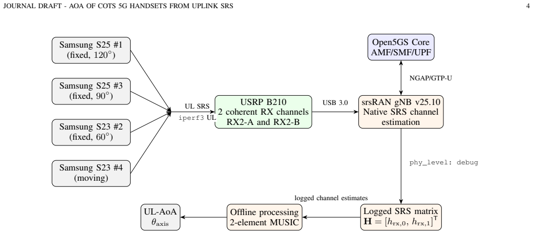
The load-bearing object is the native per-antenna SRS channel estimate H = ρ[h_rx0; h_rx1] that the gNB PHY logs at debug level: the paper's premise is that this vector preserves the true inter-antenna phase up to a real scalar ρ, so the phase difference ∠⟨c0 c1*⟩ carries the bearing. A single two-channel software-defined radio provides the coherent pair (shared local oscillator), and a one-time calibration φ_hw = +14.5° at n40 broadside removes the fixed hardware offset. MUSIC with two elements degenerates to classical phase interferometry; the closed-form arcsin estimate initializes a ±15° search over the MUSIC pseudospectrum. Comb-4 frequency-domain SRS offsets plus RNTI tags separate up
What would settle it
Compare the logged channel vector H for a fixed broadside source before and after rotating the array or changing band: if per-chain normalization, reordering, or a time-varying phase appears that a real ρ cannot absorb, the bearing estimates are invalid. More directly, repeat the n78 measurements after calibrating φ_hw at n78; if the errors do not fall to the n40 level, the inherited n40 calibration is not the limiting factor and the paper's frequency-stability assumption fails.
Extended reading notes
Core claim
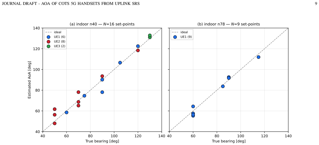
On the paper's own terms, the discovery is that native uplink SRS channel estimates from an unmodified open-source gNB carry enough spatial phase information for a calibrated two-element array to recover the bearing of commercial handsets. For each SRS occasion, the gNB logs the complex per-antenna channel vector H = ρ[h_rx0; h_rx1]; treating ρ as a real scalar and subtracting a one-time hardware phase offset φ_hw measured at broadside yields the inter-antenna phase that MUSIC converts to an angle. The indoor n40 campaign reaches 1.5° RMS error over a ±30° broadside sector; the outdoor campaign simultaneously tracks up to four handsets separated by comb-4 SRS interleaving and RNTI (radio-net
Load-bearing premise
Everything rests on the native SRS channel estimates logged by the gNB PHY preserving the true inter-antenna phase up to a real scalar ρ, and on the one-time hardware phase offset measured at n40 broadside staying constant across bands, geometries, and time.
Editorial extensions
If this is right
- A base station can offer per-UE uplink bearing estimates as a passive network service, with no phone-side changes and no extra radio hardware beyond a second receive chain.
- Two antennas can be enough for meaningful indoor accuracy (~1.5° RMS over a ±30° broadside sector), but performance degrades toward endfire and under multipath because the estimator has a single spatial baseline.
- Simultaneous multi-user operation scales with SRS multiplexing resources: the paper demonstrates four handsets and notes comb-8, cyclic shifts, and time multiplexing as standard ways to go beyond.
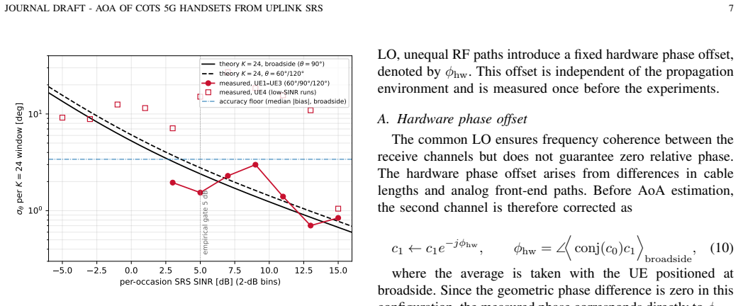
- AoA reliability is gated by SRS SINR rather than range: above roughly 5 dB in this deployment errors stay near 3°, below it they grow to 14–32°, so link-quality monitoring could serve as a validity flag for each bearing.
- Uplink communication and sensing can coexist without mutual degradation: throughput stayed near the practical limit while bearings were produced, since throughput needs post-combining SINR whereas AoA needs a clean spatial phase.
Reading between the lines
- Editorial inference: the single-LO, single-calibration design is the reason the two-antenna setup works at all; scaling to more antennas would require either one multi-channel SDR with a shared LO or external synchronization, which the paper's own comparison suggests reintroduces drift.
- Editorial inference: the n78 data provide a natural falsification experiment — if a band-specific φ_hw measurement at n78 (the conducted offset differs by ~12.5° from the n40 value) does not bring n78 errors near the n40 level, then the inherited calibration is not the main n78 penalty.
- Editorial inference: the scene-dependent sign flip of the outdoor bias (open park positive, glass facade negative) suggests a calibration step conditioned on local scattering, e.g., per-sector multipath fingerprints, could extend the usable sector beyond ±30° and reduce the systematic bias.
- Editorial inference: since the estimator cannot separate front from back, real deployments must either place users in the forward half-plane (as done here) or add a second baseline; a two-element interferometer alone cannot disambiguate a 30° target from its 150° mirror.
Editorial analysis
A structured set of objections, weighed in public.
Referee Report
Summary. The paper proposes a passive network-side uplink angle-of-arrival (AoA) estimator for COTS 5G handsets. It uses an unmodified srsRAN Project gNB with a single two-element USRP B210, extracts the native per-antenna SRS channel estimates from PHY debug logs, applies a one-time hardware phase-offset calibration plus a two-element MUSIC/phase-interferometer estimator, and validates the method through indoor n40/n78 and outdoor n40 multi-UE measurement campaigns. The main reported results are a 1.5° RMS indoor n40 error over a ±30° broadside sector, simultaneous AoA estimation for up to four handsets, and outdoor accuracy that tracks SRS SINR and multipath conditions rather than transmitter distance.
Significance. If the central logging assumption holds, the work is a useful practical demonstration: passive AoA from unmodified commercial handsets using a stock open-source gNB and a low-cost two-element SDR is a meaningful step beyond dedicated transmitters or modified RAN stacks. The paper is statistically careful in treating set-points rather than SRS occasions as the unit of replication, provides an explicit uncertainty budget, and is unusually honest about its limitations (e.g., n78 is downgraded to qualitative, the 42-m outdoor failure is a single-pass observation, and small-N rows are flagged as indicative). The multi-UE comb-4 separation and the theoretical Gaussian-noise baseline are also strengths. However, the unverified assumption about the srsRAN debug-log channel matrix is load-bearing, and the n78 results do not support quantitative claims as presented.
major comments (4)
- [III-B6, IV-A (Eq. 10)] The entire framework depends on the assertion that the phy_level=debug log records H = rho[h_rx0; h_rx1] with a real scalar rho and no per-occasion phase transformation. The paper provides no evidence for this: there is no wired back-to-back test with a known injected phase, no comparison against a calibrated reference capture, and no audit of the srsRAN v25.10 logging code path. Because Eq. (10) subtracts only a constant phase offset, any per-chain normalization, antenna reordering, or time-varying phase in the logging pipeline would corrupt every bearing estimate in a way that calibration cannot fix. This is the central load-bearing point and must be validated before the quantitative claims can be accepted.
- [IV-B/C and VII] The conducted calibration shows that phi_hw is frequency-dependent: +16.91° at n40 versus +29.38° at n78. The OTA-calibrated +14.5° value from n40 is then applied to n78, and Section VII concedes that n78 is 'qualitative only.' This is internally honest, but the abstract states that indoor measurements on 'bands n40 and n78' achieve the 1.5° RMS result, which could mislead readers into thinking n78 is quantitatively validated. Either perform band-specific OTA calibration and report n78 errors, or state explicitly in the abstract that n78 results are qualitative only.
- [Table VII, V-A2] The headline 1.5° RMS indoor n40 result rests on N=5 set-points from a single UE in one room, with no confidence interval for the RMS itself; the approximate 95% CI for the bias would be wide. The paper does disclose the effective sample size, which is good, but the abstract's unqualified 1.5° figure overstates the strength of the evidence. The claim should be rephrased as indicative, with a confidence interval reported, or the headline should pool the available set-points with an explicit uncertainty estimate.
- [VI-B and abstract] The abstract concludes that outdoor accuracy is 'primarily governed by propagation conditions and received SINR rather than transmitter distance.' This is supported mainly by one non-monotonic UE4 trajectory (2/4/27/42/61 m) and an indoor distance sweep with N=3 set-points. The paper appropriately calls the 42-m failure a single-pass observation and admits missing PHR and delay-spread measurements, but the abstract states the conclusion without these caveats. The causal claim should be softened or accompanied by the single-pass caveat in the abstract.
minor comments (5)
- [V-A5] Typo: 'Table VI ummarizes' should be 'summarizes.'
- [III-A and III-B9] The angle convention is clear (theta_axis measured from array axis, broadside 90°), but the steering vector in Eq. (3) uses sin(theta) while Eq. (1) uses cos(theta_axis). It would help to state explicitly how the two are related in the text or figure captions.
- [Figure 4 caption] Minor wording issue: 'measured, UE1 UE3' should be 'measured, UE1-UE3' or 'UE1/UE3.'
- [VI-B] The phrase '2πphase-wrap' should be '2π phase-wrap' for readability.
- [V-B3] The sentence 'the empirical CDF of Figure 10 presents...' is grammatically awkward; consider rewriting.
Circularity Check
No significant circularity: the AoA estimator, calibration, and validation are self-contained, and the main risk is an unverified logging assumption, not a definitional loop.
full rationale
The paper's derivation chain is not circular. The AoA estimator (Eqs. 1-4) follows from the standard two-element ULA geometry and the MUSIC/interferometer relation; it is not fitted to the reported data. The hardware phase offset φ_hw is measured once at broadside (Eq. 10) and then applied to independent off-broadside set-points whose true bearings come from a goniometer, so the accuracy results provide genuine external validation rather than a re-statement of a fitted input. The broadside re-check merely confirms self-consistency and is not presented as a prediction. The SRS SINR of Eq. (5) is taken from the gNB's own per-occasion log, and the theoretical precision baseline (Eqs. 6-9) is derived from a Gaussian-noise model and then compared against measurements, not fitted to them. The n78 results are explicitly downgraded to 'qualitative only' because they inherit the n40 calibration, which is an acknowledged limitation rather than a disguised prediction. No self-citation chain or imported uniqueness theorem is load-bearing; references [1]-[18] are external benchmark implementations. The genuinely weak point is the unverified assumption in Section III-B6 that the srsRAN debug log records H = ρ[h_rx0; h_rx1] with a real ρ that preserves the true inter-antenna phase. This is a correctness/robustness risk — a wired phase-injection test would strengthen it — but it is not circular, because no quantity in the estimator is defined in terms of the AoA it claims to predict, and no fitted parameter is renamed as a prediction.
Assumptions & free parameters
free parameters (2)
- Hardware phase offset φ_hw =
+14.5° (n40 OTA; conducted +16.91° at n40, +29.38° at n78)
- Empirical SRS-SINR reliability threshold =
5 dB
assumptions (6)
- domain assumption Two receive chains of the USRP B210 share one LO and maintain a fixed inter-channel phase relationship up to constant φ_hw (Section III-B1).
- domain assumption The per-antenna SRS channel estimates logged by srsRAN PHY satisfy H = ρ[h_rx0; h_rx1] with real ρ, preserving inter-antenna phase (Section III-B6).
- domain assumption Antennas are identical omnidirectional elements at d=λ/2 and mutual coupling is negligible or absorbed in calibration (Sections III-B2, IV-D).
- domain assumption Signals arrive only from the forward half-plane, resolving the front/back ambiguity (Section III-B8).
- standard math Two-element MUSIC with one baseline is a phase interferometer; steering vector a(θ)=[1, e^{j2π(d/λ) sinθ}]^T and phase relation Δφ=2πd/λ cosθ_axis (Section III-A).
- domain assumption Noise model: per-occasion complex Gaussian noise on the two channel estimates, equal SINR per chain; phase variance var(Δφ)=(1/K)(1+γ)/γ² (Eqs. (6)-(8)).
Cite this review
Pith. "Pith review of Passive AoA Estimation of COTS 5G NR Handsets from Uplink SRS: A Practical USRP-B210 Implementation." pith.science (2026). https://pith.science/paper/UZ667WW5
@misc{pith2026260800080,
  author       = {Pith},
  title        = {Pith review of: Passive AoA Estimation of COTS 5G NR Handsets from Uplink SRS: A Practical USRP-B210 Implementation},
  year         = {2026},
  howpublished = {\url{https://pith.science/paper/UZ667WW5}},
  note         = {Machine review of arXiv:2608.00080}
}
read the original abstract
This paper presents a passive network-side framework for estimating the uplink angle of arrival (AoA) of unmodified commercial 5G handsets from native Sounding Reference Signal (SRS) transmissions. The proposed system operates on an srsRAN Project gNB and estimates AoA directly from the per-antenna SRS channel estimates using a calibrated two-element Universal Software Radio Peripheral (USRP) B210 receiver and a MUSIC-based estimator, requiring neither protocol modifications nor user-equipment cooperation. Independent SRS channel estimates enable simultaneous AoA estimation for up to four commercial handsets. The framework is evaluated through indoor and outdoor measurement campaigns. Indoor measurements on bands n40 and n78 achieve a root-mean-square error of 1.5 on n40 over a 30 broadside sector. Outdoor experiments in a live 5G standalone deployment demonstrate simultaneous multi-user operation and show that estimation accuracy is primarily governed by propagation conditions and received signalto-interference-plus-noise ratio (SINR) rather than transmitter distance. These results demonstrate the feasibility of passive uplink AoA estimation using native 5G signaling, low-cost SDR hardware, and commercial handsets.
Figures


Figures from the paper (14 more)


Reference graph
Works this paper leans on
-
[1]
Angle of arrival estimation using srs in 5g nr uplink scenarios,
T. Spanos, F. Fabra, J. A. López-Salcedo, G. Seco-Granados, N. Kanis- tras, I. Lapin, and V . Paliouras, “Angle of arrival estimation using srs in 5g nr uplink scenarios,”arXiv preprint arXiv:2411.16501, 2024
arXiv 2024
-
[2]
SRS-based Wide- band AoA Estimation Method in 5G New Radio,
K. Hu, W. Li, Q. Lu, C. Shi, B. Zhao, and Y . Shen, “SRS-based Wide- band AoA Estimation Method in 5G New Radio,” in2023 IEEE/CIC International Conference on Communications in China (ICCC), pp. 1–6, IEEE, 2023. https://ieeexplore.ieee.org/document/10233433/
arXiv 2023
-
[3]
Angle of arrival estimation in a multi-antenna software defined radio system: impact of hardware and radio environment,
M. Wachowiak and P. Kryszkiewicz, “Angle of arrival estimation in a multi-antenna software defined radio system: impact of hardware and radio environment,”Wireless Networks, vol. 28, no. 8, pp. 3537–3548, 2022
2022
-
[4]
AoA services in 5G networks: A framework for real-world implementation and sys- tematic testing,
A. Ceresoli, V . Bernazzoli, R. Pegurri, and I. Filippini, “AoA services in 5G networks: A framework for real-world implementation and sys- tematic testing,”arXiv preprint arXiv:2510.17342, 2025
arXiv 2025
-
[5]
The integrated sensing and communication revolution for 6g: Vision, techniques, and applications,
N. González-Prelcic, M. F. Keskin, O. Kaltiokallio, M. Valkama, D. Dardari, X. Shen, Y . Shen, M. Bayraktar, and H. Wymeersch, “The integrated sensing and communication revolution for 6g: Vision, techniques, and applications,”Proceedings of the IEEE, vol. 112, no. 7, pp. 676–723, 2024
2024
-
[6]
Model-Driven Deep Neural Network for Enhanced AoA Estimation Using 5G gNB,
S. Liu, X. Li, Z. Mao, P. Liu, and Y . Huang, “Model-Driven Deep Neural Network for Enhanced AoA Estimation Using 5G gNB,”arXiv preprint arXiv:2501.00009, 2025
arXiv 2025
-
[7]
Evaluation of 5G Positioning Based on Uplink SRS and Downlink PRS Under LOS and NLOS Environments,
S. S. Shah, C. Sun, D. Yang, M. Wisal, Y . He, B. Lu, and Y . Xu, “Evaluation of 5G Positioning Based on Uplink SRS and Downlink PRS Under LOS and NLOS Environments,”Applied Sciences, vol. 15, no. 14, p. 7909, 2025
2025
-
[8]
Experimental Validation of an SDR-Based Direction of Arrival Estimation Testbed,
N. Sheremet and G. Fokin, “Experimental Validation of an SDR-Based Direction of Arrival Estimation Testbed,”Information, vol. 17, no. 4, p. 313, 2026
2026
Show all 22 references
-
[9]
5G Positioning — Angle Measurements Using 5G Signals and Software Defined Radios in Campus Networks
N. Sheremet and G. Fokin, “5G Positioning — Angle Measurements Using 5G Signals and Software Defined Radios in Campus Networks.” ResearchGate preprint 378610478, 2024. https://www.researchgate.net/ publication/378610478
2024
-
[10]
Experimental Investigation of AoA Estimation and Antenna Calibration with 5G NR Signals Using USRP Devices,
A. Xhafa, F. Fabra, D. Egea-Roca, J. A. López-Salcedo, and G. Seco- Granados, “Experimental Investigation of AoA Estimation and Antenna Calibration with 5G NR Signals Using USRP Devices,”IEEE Transac- tions on Instrumentation and Measurement, vol. 74, pp. 1–15, 2025
2025
-
[11]
5G NR UL SRS TDoA Positioning by OpenAirInterface,
M. Ahadi, A. Malik, F. Kaltenberger, and C. Thienot, “5G NR UL SRS TDoA Positioning by OpenAirInterface,” inICL-GNSS 2023 Work-in- Progress Papers, CEUR Workshop Proceedings, vol. 3581, 2023. https: //ceur-ws.org/V ol-3581/178_WiP.pdf
2023
-
[12]
From Concept to Reality: 5G Positioning with Open-Source Implementation of UL-TDoA in OpenAirInterface,
A. Malik, M. Ahadi, F. Kaltenberger, K. Warnke, N. T. Thinh, N. Bouk- nana, C. Thienot, G. Onche, and S. Arora, “From Concept to Reality: 5G Positioning with Open-Source Implementation of UL-TDoA in OpenAirInterface,”arXiv preprint arXiv:2409.05217, 2024
2024 arXiv
-
[13]
5G positioning with software-defined radios,
I. Palamà, Y . Lizarribar, L. M. Monteforte, G. Santaromita, S. Bartoletti, D. Giustiniano, G. Bianchi, and N. Blefari Melazzi, “5G positioning with software-defined radios,”Computer Networks, vol. 250, p. 110595, 2024
2024
-
[14]
Fuse-then-Detect for Passive UA V Localization Using Multi- UE 5G Uplink Signals,
W. Huang, N. González-Prelcic, V . Ratnam, M. Bayraktar, and C. J. Zhang, “Fuse-then-Detect for Passive UA V Localization Using Multi- UE 5G Uplink Signals,”arXiv preprint arXiv:2607.11955, 2026
2026 arXiv
-
[15]
Bistatic Sensing in 5G NR,
R. Gangula, S. Velumani, and T. Melodia, “Bistatic Sensing in 5G NR,” arXiv preprint arXiv:2505.12555, 2025
2025 arXiv
-
[16]
Utilizing 5G NR SSB Blocks for Pas- sive Detection and Localization of Low-Altitude Drones,
P. Jopanya and D. P. M. Osorio, “Utilizing 5G NR SSB Blocks for Pas- sive Detection and Localization of Low-Altitude Drones,” in2025 IEEE 26th International Workshop on Signal Processing Advances in Wireless Communications (SPAWC), pp. 1–5, IEEE, 2025. arXiv:2504.02641
2025 arXiv
-
[17]
Experimental Validation of Single Base Station 5G mmWave Positioning: Initial Findings,
Y . Ge, H. Chen, F. Jiang, M. Zhu, H. Khosravi, S. Lindberg, H. Her- bertsson, O. Eriksson, O. Brunnegård, B.-E. Olsson, P. Hammarberg, F. Tufvesson, L. Svensson, and H. Wymeersch, “Experimental Validation of Single Base Station 5G mmWave Positioning: Initial Findings,” in 202...
2022
-
[18]
Experimental Validation of Single BS 5G mmWave Positioning and Mapping for Intelligent Transport,
Y . Ge, H. Khosravi, F. Jiang, H. Chen, S. Lindberg, P. Hammarberg, H. Kim, O. Brunnegård, O. Eriksson, B.-E. Olsson, F. Tufvesson, L. Svensson, and H. Wymeersch, “Experimental Validation of Single BS 5G mmWave Positioning and Mapping for Intelligent Transport,” arXiv preprint...
2023 arXiv
-
[19]
USRP B210 Product Datasheet
Ettus Research (National Instruments), “USRP B210 Product Datasheet.” https://www.ettus.com/all-products/ub210-kit/. Accessed: 2026-07-14
2026
-
[20]
AD9361 RF Agile Transceiver Datasheet
Analog Devices, “AD9361 RF Agile Transceiver Datasheet.” https:// www.analog.com/en/products/ad9361.html. Accessed: 2026-07-14
2026
-
[21]
OMNI-A0085 (OMNI-85) Datasheet
Poynting Antennas, “OMNI-A0085 (OMNI-85) Datasheet.” https:// www.poynting.tech/antennas/omni-85/. Accessed: 2026-07-14
2026
-
[22]
NR; Physical layer procedures for data,
3GPP, “NR; Physical layer procedures for data,” Tech. Rep. TS 38.214, 3GPP, 2020
2020
Reviewed August 4, 2026 · model on record in the stance chip above.
Discussion (0). Continue with ORCID to comment.