REVIEW 2 major objections 6 minor 27 references
Dissipation without resistance: Imaging impurities at quantum Hall edges
T0 review · 2 major / 6 minor · reviewed 2026-08-14 · deepseek-v4-flash
Pith's one-line read Resonant impurities in quantum Hall edges cause nonlocal phonon emission without adding resistance.
desk verdict Worth a serious referee, but the central rate is not established as written: Appendix B omits the M0-Ms interference terms, and those terms are the same order as the claimed impurity contribution. read the letter →
The pith
A machine-rendered reading of the paper's core claim, the machinery that carries it, and where it could break.
The reading
What carries the argument
The central object is a resonant level (a 'quantum dot') side-attached to a single chiral edge mode, described by $H_{\mathrm{dot}} = \epsilon_d d^\dagger d + t\sum_k(c_k^\dagger d + \mathrm{h.c.})$, where $\Gamma=\pi\rho t^2$ is the impurity level broadening. Its scattering state, derived by the operator method of Ref. [26], is a plane wave with the momentum-dependent phase shift $\theta_k = -2\arctan[\Gamma/(\epsilon_k-\epsilon_d)]$. That phase shift enters the phonon-induced matrix element $M_s$ of Eq. (14); unlike a scalar potential, it does not cancel, and its absolute square, combined with the impurity-free baseline $P_0$ and the heat-diffusion equation for the phonon bath, yields the central dissipation rate Eq. (15) and the ring-shaped lattice-temperature profile.
What would settle it
Calculate $|M_0+M_s|^2$ including the cross terms that Eq. (8) leaves unevaluated; if those cross terms contribute at leading order, Eq. (15) is not the full dissipation rate. In experiment, a detector tip downstream of an on-resonance impurity should see a persistent temperature step with no change in local or two-terminal Hall resistance; observing instead a locally decaying hotspot or any voltage drop correlated with the ring would falsify the central claim.
Extended reading notes
Core claim
Central claim: in a single chiral 1D channel, forward scattering at a resonant impurity creates a momentum-dependent phase shift $\theta_k = -2\arctan[\Gamma/(\epsilon_k-\epsilon_d)]$ in the electron wave function. A scalar potential produces only a momentum-independent phase and hence no extra phonon matrix element; the momentum dependence is what turns the impurity into a source of phonon emission. The resulting impurity-induced dissipation rate per unit length is $P_{\mathrm{imp}} = 4P_0\,\Gamma^2/(\Gamma^2+\epsilon_d^2)$, where $P_0$ is the clean-edge rate from Ref. [14], in both the high- and low-temperature regimes. This rate has two properties: it is not accompanied by any local voltage drop, and it is constant over the whole downstream edge segment, so a single impurity heats the edge globally. The Lorentzian dependence on $\epsilon_d$ is the origin of the thermal rings: as the scanning tip tunes the impurity level, the dissipation switches on and off.
Load-bearing premise
The calculation's load-bearing assumption is that the phonon-emission rate from the full wave function is the clean-edge rate plus the rate computed from the impurity-scattered part alone; if the interference between these two parts of the wave function is not negligible, the claimed rate and its fourfold enhancement would change.
Editorial extensions
If this is right
- On resonance, a boundary impurity emits phonons at four times the clean-edge rate per unit length; with the paper's parameters this adds roughly 250 to 350 µK to the lattice temperature for a 50-nm ring, consistent with the reported images.
- The ring appears as a geometric resonance condition: as the tip voltage tunes $\epsilon_d$ through zero, the ring thickness is about $r_{\mathrm{ring}}\Gamma/V_{\mathrm{tip}}$, much thinner than the ring radius, explaining the sharp contrast of the images.
- Because the dissipation rate is independent of position downstream, the heat source is the whole edge segment beyond the impurity, and the electron temperature cools along the edge with a characteristic cooling length $l_{\mathrm{cool}}\approx 20\,\mu\mathrm{m}$.
- The dissipation is decoupled from resistance: no local voltage drop or change in Hall conductance accompanies the enhanced phonon emission, unlike two-dimensional supercollision heating where dissipation and resistance appear together.
- In a two-tip experiment, moving the detector across the on-resonance impurity should produce an abrupt lattice-temperature enhancement downstream, while upstream the profile stays smooth, providing a direct signature of nonlocal dissipation.
Reading between the lines
- If this picture holds, the sharpness of a thermal ring directly encodes the tunnel broadening $\Gamma$ and the tip's lever arm on the impurity level, so the technique becomes a local spectroscopy of boundary impurities rather than only an imaging tool.
- The same mechanism should operate in any chiral one-dimensional conductor with resonant side states, such as fractional quantum Hall edges or helical edge states, though interactions and counter-propagating modes may alter the ring shape and the extent of downstream heating.
- The separation of energy dissipation from momentum relaxation suggests that the usual Joule-heating relation between dissipation and resistance fails for chiral edges, which may matter for interpreting thermal transport and noise in quantum Hall circuits.
- A direct check of the uncomputed interference term would be a numerical evaluation of the full phonon matrix element $|M_0+M_s|^2$ for the scattering state of Eq. (12); even if the factor 4 changes, the resonant and nonlocal qualitative picture could survive.
Signed reviews
Editorial analysis
A structured set of objections, weighed in public.
Referee Report
Summary. The authors study energy dissipation in a chiral quantum Hall edge in the presence of a resonant impurity. Using a single-particle scattering-state description, they find that forward scattering at the impurity produces a momentum-dependent phase shift, which leads to an impurity-induced phonon emission rate P_imp with a Lorentzian dependence on the detuning ε_d. At resonance, P_imp is four times the impurity-free rate P0, and the dissipation is uniform along the edge downstream from the impurity. They connect this mechanism to the thermal rings observed by Marguerite et al., estimate a temperature enhancement of 250–350 μK, and propose a two-tip experiment to test the nonlocal character of the dissipation. The paper also discusses the role of edge reconstruction and the contribution of electrons trapped on the impurity.
Significance. If the central result Eq. (15) is correct, the paper establishes a mechanism for dissipation without resistance in chiral one-dimensional systems, explains the experimentally observed thermal rings, and provides a falsifiable two-tip measurement. The manuscript is clearly written, contains a self-contained derivation of the scattering states, and gives quantitative estimates with a concrete experimental connection. The main weakness is that the derivation of the central formula omits the interference term between the impurity-free and impurity-scattered contributions to the phonon matrix element; this term is not obviously negligible and must be computed or argued to vanish before the quantitative predictions are reliable.
major comments (2)
- [Sec. III.C and Appendix B (Eq. B4)] The central rate Eq. (15) is derived by adding the impurity-free contribution P0, Eq. (9), to the impurity contribution computed from |Ms|^2 alone, as stated at the beginning of Appendix B: 'only the contribution from Ms will be calculated.' The full squared matrix element for the rate is |M0 + Ms|^2 = |M0|^2 + |Ms|^2 + 2 Re(M0^* Ms). The interference term 2 Re(M0^* Ms) is non-vanishing: at the momentum-conserving kinematics selected by M0 (k1 - k2 = qx), Ms is proportional to (L/2 - x0)/L [e^{-i(θk1-θk2)} - 1], which is not zero for a momentum-dependent phase shift θk. For the resonant impurity, θk1 - θk2 is of order Γ v qx / [(vk - μ - εd)^2 + Γ^2]; this does not vanish, and because it enters linearly rather than quadratically, it can be comparable to or larger than |Ms|^2. Consequently, Eq. (15), the factor-4 enhancement used in Eq. (24), and the quoted 250–350 μK temperature enhancement are not established by the calculation as written. The authors should compute the interference term or provide a symmetry argument for its vanishing.
- [Appendix B, Eq. (B2)] The sentence preceding Eq. (B2) states that 'typically qx ≫ k1,k2'. This is not the correct ordering: for acoustic phonons at temperature T, qx ~ qT = k_B T/s, which is much smaller than the electron momenta k1,k2 near the Fermi surface. The condition that is actually needed for the reduction in Eq. (B2) is qx ≫ |k1 - k2| = (s/v) qx, which holds because s ≪ v. Please correct this statement; as written it is misleading and undermines the clarity of the derivation.
minor comments (6)
- [Introduction, paragraph 2] The word 'producse' in 'this forward scattering of electrons at quantum Hall edges leads to an enhanced phonon emission, which reaches its maximum when the impurity state is tuned to resonance by a scanning tip voltage' should be 'produces'.
- [Appendix A and Sec. IV.A] The symbol η is used both for the positive infinitesimal in the scattering-state derivation around Eq. (A4) and for the energy-input efficiency in Eq. (19). Please use a different symbol for one of them to avoid confusion.
- [Eqs. (B5)-(B6)] The notation Γ(2)ζ(2) and Γ(6)ζ(6) is correct but opaque; the numerical factors 2ζ(2) = π^2/3 and 720ζ(6) = 8π^6/63 would make the comparison with P0 in Eq. (9) more transparent.
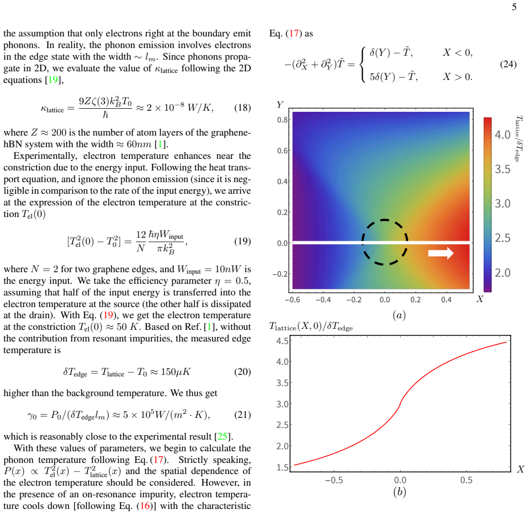
- [Fig. 3] The color scale and units of the temperature profile in Fig. 3(a) are not defined; adding a color bar and specifying the normalization used for Tlattice/δTedge would make the figure clearer.
- [Sec. IV.A, Eq. (21)] The parameter γ0 is fixed by using the theoretical P0 and the experimental δTedge, so the subsequent 250–350 μK estimate is a calibrated comparison rather than an independent prediction. This should be explicitly acknowledged when presenting the numerical agreement.
- [Sec. IV.A, after Eq. (17)] The phrase 'we simply the model with the assumption' should read 'we simplify the model with the assumption'.
Circularity Check
No significant circularity: Eq. (15) follows from the stated scattering model, and the Sec. IV.A use of the measured background temperature is a calibration consistency check, not a constructed equivalence.
full rationale
The central result, Eq. (15), is derived within the paper from the scattering-state phase shift (13), the matrix element decomposition (8), and the impurity-free rate P0 taken from Ref. [14], which is an external benchmark rather than a self-citation. No parameter entering Eq. (15) is fitted to the experimental thermal rings; the resonant Lorentzian line shape and the factor 4 relative to P0 follow algebraically from |Ms|^2 in Appendix B. The Appendix B calculation explicitly evaluates only the |Ms|^2 contribution (Eq. B4) and therefore omits the M0-Ms interference term from Eq. (8); this is a possible technical gap in the derivation, but it is an approximation issue, not a circularity, because the claimed result is not defined in terms of, or fitted to, the output. The Sec. IV.A estimate does use the measured impurity-free edge-temperature rise δTedge ≈ 150 µK to fix γ0 via Eq. (21), and the resulting 250-350 µK ring amplitude is a consistency check against Ref. [1] rather than a quantity statistically forced by that input; the ring amplitude is controlled by the theoretical ratio Pimp/P0 = 4 and the heat-diffusion geometry. The self-citations [16, 18] provide context and comparison with 2D supercollisions and do not carry the derivation. Overall, the derivation is self-contained against an external benchmark, so no circular step is reported.
Assumptions & free parameters
free parameters (2)
- η (energy input efficiency) =
0.5
- γ0 (phonon-bath coupling) =
≈ 5e5 W/(m^2·K)
assumptions (5)
- domain assumption The system is in the integer quantum Hall regime with a single chiral channel (filling factor ν=2, spin degeneracy ignored).
- domain assumption The impurity is a single resonant level side-coupled to the edge with momentum-independent coupling t.
- domain assumption The electron-phonon interaction is weak and treated by Fermi's golden rule with the form factor F(q) of Ref. [14]; the k-dependence of the form factor is neglected.
- ad hoc to paper The phase shift is small, Γ, ε_d ≪ k_B T_el, so that exp[-i(θk2-θk1)] - 1 ≈ -2Γ/(ε_d + iΓ).
- ad hoc to paper Edge reconstruction is negligible for the downstream dissipation mechanism.
Cite this review
Pith. "Pith review of Dissipation without resistance: Imaging impurities at quantum Hall edges." pith.science (2026). https://pith.science/paper/VJCNYE3E
@misc{pith2026190805035,
  author       = {Pith},
  title        = {Pith review of: Dissipation without resistance: Imaging impurities at quantum Hall edges},
  year         = {2026},
  howpublished = {\url{https://pith.science/paper/VJCNYE3E}},
  note         = {Machine review of arXiv:1908.05035}
}
read the original abstract
Motivated by the recent experiment by Marguerite et al. [1] on imaging in graphene samples, we investigate theoretically the dissipation induced by resonant impurities in the quantum Hall regime. The impurity induced forward scattering of electrons at quantum Hall edges leads to an enhanced phonon emission, which reaches its maximum when the impurity state is tuned to resonance by a scanning tip voltage. Our analysis of the effect of the tip potential on the dissipation reveals peculiar thermal rings around the impurities, in consistency with experimental observations. Remarkably, this impurity-induced dissipation reveals non-trivial features that are unique for chiral 1D systems such as quantum Hall edges. First, the dissipation is not accompanied by the generation of resistance. Second, this type of dissipation is highly nonlocal: a single impurity induces heat transfer to phonons along the whole edge.
Figures


Reference graph
Works this paper leans on
-
[1]
A. Marguerite, J. Birkbeck, A. Aharon-Steinberg, D. Halbertal, K. Bagani, I. Marcus, Y . Myasoedov, A. K. Geim, D. J. Perello, and E. Zeldov, Nature 575, 628 (2019)
work page 2019
-
[2]
Giamarchi, Quantum Physics in One Dimension (Oxford University Press, Oxford UK, 2004)
T. Giamarchi, Quantum Physics in One Dimension (Oxford University Press, Oxford UK, 2004)
work page 2004
-
[3]
P. Fendley, A. W. W. Ludwig, and H. Saleur, Phys. Rev. Lett. 74, 3005 (1995)
work page 1995
-
[4]
C. L. Kane and M. P. A. Fisher, Phys. Rev. B52, 17393 (1995)
work page 1995
-
[5]
C. L. Kane and E. J. Mele, Phys. Rev. Lett. 95, 226801 (2005)
2005
-
[6]
Alicea, Reports on Progress in Physics 75, 076501 (2012)
J. Alicea, Reports on Progress in Physics 75, 076501 (2012)
2012
-
[7]
N. H. Lindner, E. Berg, G. Refael, and A. Stern, Phys. Rev. X 2, 041002 (2012)
work page 2012
- [8]
Show all 27 references
-
[9]
Motruk, E
J. Motruk, E. Berg, A. M. Turner, and F. Pollmann, Phys. Rev. B 88, 085115 (2013)
2013
-
[10]
D. J. Clarke, J. Alicea, and K. Shtengel, Nature Physics 10, 877 EP (2014)
2014
-
[11]
R. S. K. Mong, D. J. Clarke, J. Alicea, N. H. Lindner, P. Fend- ley, C. Nayak, Y . Oreg, A. Stern, E. Berg, K. Shtengel, and M. P. A. Fisher, Phys. Rev. X4, 011036 (2014)
2014
-
[12]
San-Jose, J
P. San-Jose, J. L. Lado, R. Aguado, F. Guinea, and J. Fern´andez-Rossier, Phys. Rev. X 5, 041042 (2015)
2015
-
[13]
Alicea and P
J. Alicea and P. Fendley, Annual Review of Condensed Matter Physics 7, 119 (2016)
2016
-
[14]
Slizovskiy and V
S. Slizovskiy and V . Fal’ko, Phys. Rev. B96, 075434 (2017)
2017
-
[15]
Rokni and Y
M. Rokni and Y . Levinson, Phys. Rev. B52, 1882 (1995)
1995
-
[16]
K. S. Tikhonov, I. V . Gornyi, V . Y . Kachorovskii, and A. D. Mirlin, Phys. Rev. B 100, 205430 (2019)
2019
-
[17]
Halbertal, M
D. Halbertal, M. Ben Shalom, A. Uri, K. Bagani, A. Y . Meltzer, I. Marcus, Y . Myasoedov, J. Birkbeck, L. S. Levitov, A. K. Geim, and E. Zeldov, Science 358, 1303 (2017)
2017
-
[18]
K. S. Tikhonov, I. V . Gornyi, V . Y . Kachorovskii, and A. D. Mirlin, Phys. Rev. B 97, 085415 (2018)
2018
-
[19]
J. F. Kong, L. Levitov, D. Halbertal, and E. Zeldov, Phys. Rev. B 97, 245416 (2018)
2018
-
[20]
Vasyukov, Y
D. Vasyukov, Y . Anahory, L. Embon, D. Halbertal, J. Cuppens, L. Neeman, A. Finkler, Y . Segev, Y . Myasoedov, M. L. Rappa- port, M. E. Huber, and E. Zeldov, Nature Nanotechnology 8, 639 EP (2013)
2013
-
[21]
Halbertal, J
D. Halbertal, J. Cuppens, M. B. Shalom, L. Embon, N. Shadmi, Y . Anahory, H. R. Naren, J. Sarkar, A. Uri, Y . Ronen, Y . Mya- soedov, L. S. Levitov, E. Joselevich, A. K. Geim, and E. Zel- dov, Nature 539, 407 (2016)
2016
-
[22]
Ihn, Semiconductor Nanostructures (Oxford University Press, Oxford, 2010)
T. Ihn, Semiconductor Nanostructures (Oxford University Press, Oxford, 2010)
2010
-
[23]
P. G. Silvestrov and K. B. Efetov, Phys. Rev. B 77, 155436 (2008)
2008
-
[24]
J. C. W. Song, M. Y . Reizer, and L. S. Levitov, Phys. Rev. Lett. 109, 106602 (2012)
2012
-
[25]
Z. Chen, W. Jang, W. Bao, C. N. Lau, and C. Dames, Applied Physics Letters 95, 161910 (2009), https://doi.org/10.1063/1.3245315
2009 doi
-
[26]
Schiller and S
A. Schiller and S. Hershfield, Phys. Rev. B 58, 14978 (1998)
1998
-
[27]
Bruus and K
H. Bruus and K. Flensberg, Many-Body Quantum Theory in Condensed Matter Physics (Oxford University Press, New York, 2004)
2004
Reviewed August 14, 2026 · model on record in the stance chip above.
Discussion (0). Continue with ORCID to comment.