REVIEW 3 major objections 5 minor 1 cited by
Magnetic signatures of domain walls in $s+is$ and $s+id$ superconductors: observability and what that can tell us about the superconducting order parameter
T0 review · 3 major / 5 minor · reviewed 2026-08-14 · deepseek-v4-flash
Pith's one-line read Pinned domain walls in anisotropic broken-time-reversal superconductors carry orientation-dependent magnetic fields that can identify s+is versus s+id pairing.
desk verdict The orientation-resolved magnetic signature of domain walls is a solid, symmetry-based diagnostic for s+is vs s+id, but the observability claim needs parameter sensitivity analysis before it can be trusted. read the letter →
The pith
A machine-rendered reading of the paper's core claim, the machinery that carries it, and where it could break.
The reading
What carries the argument
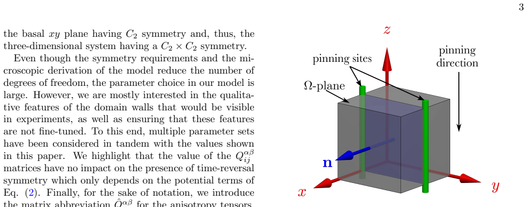
The central object is the effective two-component Ginzburg-Landau free energy with anisotropic gradient tensors $\hat{Q}^{\alpha\beta}$, in which the inter-component tensor $\hat{Q}^{12}$ encodes the pairing symmetry. For s+is, $Q^{12}_{xx}=Q^{12}_{yy}$ on the basal plane, leaving a continuous rotation symmetry; for s+id, $Q^{12}_{xx}=-Q^{12}_{yy}$, leaving only a two-fold symmetry. These tensors couple gradients of the relative phase $\theta_{12}$ to the vector potential, so a phase-difference kink whose normal breaks the lattice symmetry generates a spontaneous magnetic field along the wall. The computational procedure is to solve the resulting Ginzburg-Landau equations on a two-dimensional cross section with two parallel columnar pinning centers, parametrizing all possible walls by the unit normal vector on the upper hemisphere.
What would settle it
In a sample with two parallel columnar pinning tracks that fix a domain-wall normal rotated $45^\circ$ within the basal plane, scan the magnetic field along the wall with a scanning Hall probe or SQUID. Absence of an extended field would rule out the s+id description for that material; presence of an extended field in a sample expected to be s+is would mean the assumed $Q^{12}_{xx}=Q^{12}_{yy}$ symmetry is wrong.
Extended reading notes
Core claim
Within the effective two-component Ginzburg-Landau theory derived for a three-band repulsive model, a straight domain wall pinned between two columnar defects produces a bulk spontaneous magnetic field whenever the wall normal is not aligned with a crystalline axis, for both s+is and s+id states. For rotations of the wall within the basal plane, the s+is wall stays field-free away from the pinning sites because that plane has continuous rotational symmetry, whereas the s+id wall develops an extended field because its basal-plane symmetry is only two-fold. Rotating the wall about another crystalline axis gives both states extended fields whose magnitudes are comparable in the tested parameter set, yet whose maps over the full orientation sphere are clearly different. The authors conclude that measuring the magnetic response of pinned domain walls as a function of wall orientation can determine the pairing symmetry.
Load-bearing premise
The load-bearing premise is that the anisotropy tensors and coupling parameters chosen for the calculations faithfully represent the band structure of the material; if the real band anisotropies differ, the predicted field strengths and parts of the orientation dependence would change.
Editorial extensions
If this is right
- A bulk magnetic field running the full length of a pinned domain wall would be direct evidence that lattice anisotropy couples to the phase-difference kink, not merely an artifact of pinning geometry.
- For wall normals in the basal plane away from crystal axes, s+id walls produce an extended field while s+is walls do not, giving an immediate yes/no discriminator.
- For walls tilted out of the basal plane, both states produce extended fields, so full orientation scans—not single snapshots—are needed to extract the pairing symmetry.
- Pinned domain walls contribute to spontaneous magnetic signals at a level comparable to impurity-modulation fields, so they should be included when interpreting muon spin rotation data in Ba$_{1-x}$K$_x$Fe$_2$As$_2$.
Reading between the lines
- Editorial inference: The same orientation-resolved protocol could test other multiband BTRS candidates; a measured angular map matching neither s+is nor s+id would indicate a different pairing symmetry or stronger anisotropy effects than the chosen parameters allow.
- Editorial inference: Since the extended wall field is predicted to be about an order of magnitude weaker than a vortex field, detection is most plausible in quenched samples with deliberately oriented pinning tracks and scanning probes rather than in as-grown samples with uncontrolled wall orientations.
- Editorial inference: If the orientation-dependent magnetic energy of the wall is large enough, it would make certain wall normals energetically preferred; counting the distribution of wall orientations after a quench could therefore provide a cheap, indirect check of the predicted orientation map.
Signed reviews
Editorial analysis
A structured set of objections, weighed in public.
Referee Report
Summary. Using an effective two-component Ginzburg-Landau functional derived from a three-band microscopic model, the paper studies straight, pinned domain walls in s+is and s+id superconductors with anisotropic gradient tensors. It shows that, away from special orientations where the wall lies in a crystalline plane, the domain wall carries a spontaneous bulk magnetic field extending along the wall. The orientation dependence is qualitatively different for the two states: s+is has SO(2) symmetry in the basal plane and s+id has C2 symmetry. For the single parameter set used, the domain-wall field is about an order of magnitude below the vortex field, and the authors propose muon-spin-rotation, SQUID, and scanning-Hall measurements on deliberately oriented pinning tracks as a route to identify the pairing symmetry. The paper also reports an orientation-averaged ratio |Bmax|_s+is / |Bmax|_s+id of roughly 2/3.
Significance. If substantiated, the paper gives a concrete, falsifiable observable distinction between s+is and s+id states, which is a central open problem for Ba1-xKxFe2As2. The main strength is that the symmetry dichotomy is robust and simple: it follows from the structure of Q12, being proportional to the identity in the basal plane for s+is and to diag(1,-1) for s+id. The mapping from microscopic band-anisotropy tensors K^(alpha) to the effective GL tensors Q^(alpha beta) is explicit, and the numerical method is standard. The proposed orientation-resolved magnetic-field map is a genuinely new diagnostic and is worth publishing once the quantitative basis for the observability claim is strengthened.
major comments (3)
- [Complete configuration space and Appendix, Tables II/III] The quantitative claims on which the observability argument rests — fields "only an order of magnitude smaller" than a vortex, the color map in Fig. 5, and the average ratio ≈2/3 — are all obtained from a single point in parameter space (η=5, λ=4.5, τ=0.2, q=0.25, with the K tensors of Table II). The text states that multiple parameter sets were considered, but no results or sensitivity analysis are shown. Since the anisotropy ratios Kxx/Kzz and Kyy/Kzz are only bracketed in [1,5] (Appendix, Refs. [36,37]) and the chosen tensors are particular points in that box, the field magnitudes for the diagnostic orientations could change substantially, possibly falling below detection thresholds. I ask for a systematic scan over the allowed anisotropy ranges and over the GL couplings, reporting the spread and minima of |Bmax| and the resulting robustness of the s+is versus s+id distinction. Without this, the title's "observability" claim is not supported, even though the qualitative C2 versus SO(2) distinction is protected by symmetry.
- [Magnetic signatures and numerical solutions; Conclusion] The comparison of the domain-wall field with the vortex field is made in the same dimensionless units, but the manuscript never gives the mapping from these units to physical magnetic field values for Ba1-xKxFe2As2. The proposed detection methods (muSR, SQUID, scanning Hall probes) have definite sensitivity thresholds, so the claim that the signal is observable requires either a conversion to physical units using realistic penetration depths, coherence lengths, and normalizations, or a clear statement of what the quoted "order of magnitude" means in absolute units. Please add this conversion, or explicitly reframe the claim as a relative-field prediction rather than an observability statement.
- [Complete configuration space, Fig. 5] Fig. 5 is the central diagnostic of the paper, but it does not state whether |Bmax| is the maximum over the entire computational domain (including pinning-localized fields) or over the bulk region away from the pinning sites. The text carefully distinguishes bulk from pinning-localized responses for the special geometries, yet Fig. 5 appears to report a global maximum; if the s+is basal-plane case has non-zero pinning-localized fields, the map may not represent the effect being advocated. Please specify the extraction procedure, provide numerical color scales, and mark the directions where symmetry forces the bulk field to vanish.
minor comments (5)
- [Appendix, Eq. (7) around Eqs. (12)-(17)] The notation for τ in Eq. (14) should be checked against Eq. (7): the sign convention is not made explicit, and a reader cannot verify the expansions without consulting Refs. [13,29].
- [References and in-text citations] Several citations are broken in the text, e.g., "[3; 6 ?]" in the Introduction and "Grinenko et." in the Conclusion; these should be fixed before publication.
- [Fig. 5 caption and color bar] The figure has no color scale or axis labels for the sphere, making it difficult to compare the s+is and s+id panels quantitatively; please add a color bar and numerical values.
- [System setup] The experimental claim that two parallel columnar pinning sites or surface dents can fix an arbitrary domain-wall orientation assumes that the wall will be straight and will span the two defects; the line-tension and metastability aspects of this assumption are not discussed.
- [Numerical methods] The manuscript states that FreeFEM and conjugate-gradient flow were used, but gives no mesh size, tolerance, or convergence criterion; adding these details would support the quantitative claims.
Circularity Check
No circularity: domain-wall field maps are computed from a microscopic GL model with parameters fixed a priori, not fitted to the predicted observables.
full rationale
The paper's derivation chain runs from a three-band microscopic model (Eq. 7) to an effective two-component Ginzburg-Landau functional (Eqs. 12-17) via a transformation adopted from Refs. [13,29] and summarized in the Appendix. The s+is versus s+id distinction enters through the symmetry-imposed sign structure of the anisotropy tensor Q12 (Table I and Eq. 16), which is a model input derived from the lattice symmetries of s-wave versus d-wave components, not from the magnetic response being predicted. The numerical solutions in Figs. 3-5 are obtained by solving the full GL equations including the vector potential; the magnetic fields are outputs of the simulation, not fitted quantities. No parameter is tuned to reproduce a measured domain-wall field, and the orientation-dependent C2 versus SO(2) pattern follows from solving the model, not from inserting the desired answer. The self-citations [13,26-29] supply the GL reduction and the known gradient/phase coupling, but the paper reproduces the relevant equations in the Appendix and the cited derivations are parameter-free with stated microscopic assumptions that do not include the target domain-wall magnetic-field orientation maps. Parameter sensitivity and the choice of a single anisotropy point are legitimate robustness/correctness concerns, but they do not make the derivation circular.
Assumptions & free parameters
free parameters (5)
- eta (microscopic interband coupling) =
5
- lambda (microscopic interband coupling) =
4.5
- tau = 1 - T/Tc =
0.2
- q (matter-field charge) =
0.25
- band anisotropy tensors K^(alpha) =
see Table II
assumptions (5)
- domain assumption Three-band repulsive interband model Eq. (1) describes the BTRS state in iron pnictides such as Ba1-xKxFe2As2.
- domain assumption The effective two-component GL expansion, Eqs. (2-3), is valid near Tc for clean three-band superconductors with the coupling matrix in Eq. (1).
- domain assumption Domain walls are translationally invariant along the pinning direction; the fields depend only on (x',y') in the pinning frame.
- domain assumption The symmetry assignments Q12_xx = Q12_yy for s+is and Q12_xx = -Q12_yy for s+id correctly encode the two pairing symmetries.
- domain assumption Irradiated tracks and surface dents are equivalent within the GL formulation for pinning domain walls.
Cite this review
Pith. "Pith review of Magnetic signatures of domain walls in $s+is$ and $s+id$ superconductors: observability and what that can tell us about the superconducting order parameter." pith.science (2026). https://pith.science/paper/VXIX2QLL
@misc{pith2026190807969,
  author       = {Pith},
  title        = {Pith review of: Magnetic signatures of domain walls in $s+is$ and $s+id$ superconductors: observability and what that can tell us about the superconducting order parameter},
  year         = {2026},
  howpublished = {\url{https://pith.science/paper/VXIX2QLL}},
  note         = {Machine review of arXiv:1908.07969}
}
abstract
One of the defining features of spontaneously broken time-reversal symmetry (BTRS) is the existence of domain walls, the detection of which would be strong evidence for such systems. There is keen interest in BTRS currently, in part, due to recent muon spin rotation experiments, which have pointed towards $\textrm{Ba}_{1-x}\textrm{K}_x\textrm{Fe}_2\textrm{As}_2$ exhibiting a remarkable case of $s$-wave superconductivity with spontaneously broken time-reversal symmetry. A key question, however, is how to differentiate between the different theoretical models which describe such a state. Two particularly popular choices of model are $s+is$ and $s+id$ superconducting states. In this paper, we obtain solutions for domain walls in $s+is$ and $s+id$ systems, including the effects of lattice anisotropies. We show that, in general, both models exhibit spontaneous magnetic field, that extend along the entire length of the domain wall. We demonstrate the qualitative difference between the magnetic signatures of $s+is$ and $s+id$ domain walls and propose a procedure to extract the superconducting pairing symmetry from the magnetic-field response of domain walls.
Figures


Figures from the paper (1 more)

Forward citations
Cited by 1 Pith paper
-
Comment on the paper by D. Efremov and Yu.N. Ovchinnikov "Singular ground state of multiband inhomogeneous superconductors", Phys. Rev. B 99, 224508 (2019)
Silaev, Winyard and Babaev show that the zero-current state proposed by Efremov and Ovchinnikov is not a solution of the full Ginzburg-Landau equations, so its no-spontaneous-field conclusion is invalid.
Reference graph
Works this paper leans on
-
[1]
V. Grinenko, P. Materne, R. Sarkar, H. Luetkens, K. Ki- hou, C. H. Lee, S. Akhmadaliev, D. V. Efremov, S.-L. Drechsler, and H.-H. Klauss, Phys. Rev. B 95, 214511 (2017)
work page 2017
-
[2]
V. Grinenko, R. Sarkar, K. Kihou, C. Lee, I. Morozov, S. Aswartham, B. B¨ uchner, P. Chekhonin, W. Skrotzki, K. Nenkov, et al. , arXiv preprint arXiv:1809.03610 (2018)
arXiv 2018
- [3]
- [4]
-
[5]
J. Carlstr¨ om, J. Garaud, and E. Babaev, Phys. Rev. B 84, 134518 (2011). 9
work page 2011
- [6]
-
[7]
J. B¨ oker, P. A. Volkov, K. B. Efetov, and I. Eremin, Phys. Rev. B 96, 014517 (2017)
work page 2017
- [8]
Show all 37 references
-
[9]
Garaud and E
J. Garaud and E. Babaev, Phys. Rev. Lett. 112, 017003 (2014)
2014
-
[10]
Maiti, M
S. Maiti, M. Sigrist, and A. Chubukov, Phys. Rev. B 91, 161102 (2015)
2015
-
[11]
S.-Z. Lin, S. Maiti, and A. Chubukov, Physical Review B 94, 064519 (2016)
2016
-
[12]
Silaev, J
M. Silaev, J. Garaud, and E. Babaev, Phys. Rev. B 92, 174510 (2015)
2015
-
[13]
Garaud, M
J. Garaud, M. Silaev, and E. Babaev, Phys. Rev. Lett. 116, 097002 (2016)
2016
-
[14]
Garaud, A
J. Garaud, A. Corticelli, M. Silaev, and E. Babaev, Phys- ical Review B 98, 014520 (2018)
2018
-
[15]
V. L. Vadimov and M. A. Silaev, Phys. Rev. B98, 104504 (2018)
2018
-
[16]
Silaev and E
M. Silaev and E. Babaev, Phys. Rev. B 88, 220504 (2013)
2013
-
[17]
Lin and X
S.-Z. Lin and X. Hu, Phys. Rev. Lett.108, 177005 (2012)
2012
-
[18]
Marciani, L
M. Marciani, L. Fanfarillo, C. Castellani, and L. Ben- fatto, Phys. Rev. B 88, 214508 (2013)
2013
-
[19]
Garaud, J
J. Garaud, J. Carlstr¨ om, and E. Babaev, Phys. Rev. Lett. 107, 197001 (2011)
2011
-
[20]
Garaud, J
J. Garaud, J. Carlstr¨ om, E. Babaev, and M. Speight, Phys. Rev. B 87, 014507 (2013)
2013
-
[21]
P. J. Hirschfeld, D. Altenfeld, I. Eremin, and I. I. Mazin, Phys. Rev. B 92, 184513 (2015)
2015
-
[22]
P. G. Bj¨ ornsson, Y. Maeno, M. E. Huber, and K. A. Moler, Phys. Rev. B 72, 012504 (2005)
2005
-
[23]
C. W. Hicks, J. R. Kirtley, T. M. Lippman, N. C. Koshnick, M. E. Huber, Y. Maeno, W. M. Yuhasz, M. B. Maple, and K. A. Moler, Phys. Rev. B 81, 214501 (2010)
2010
-
[24]
Nishio, V
T. Nishio, V. H. Dao, Q. Chen, L. F. Chibotaru, K. Kad- owaki, and V. V. Moshchalkov, Phys. Rev. B 81, 020506 (2010)
2010
-
[25]
Gutierrez, B
J. Gutierrez, B. Raes, A. Silhanek, L. Li, N. Zhigadlo, J. Karpinski, J. Tempere, and V. Moshchalkov, Physical Review B 85, 094511 (2012)
2012
-
[26]
Silaev, T
M. Silaev, T. Winyard, and E. Babaev, Phys. Rev. B 97, 174504 (2018)
2018
-
[27]
Winyard, M
T. Winyard, M. Silaev, and E. Babaev, Phys. Rev. B 99, 064509 (2019)
2019
-
[28]
Winyard, M
T. Winyard, M. Silaev, and E. Babaev, Phys. Rev. B 99, 024501 (2019)
2019
-
[29]
Garaud, M
J. Garaud, M. Silaev, and E. Babaev, Physica C: Super- conductivity and its Applications 533, 63 (2017)
2017
- [30]
-
[31]
Espinosa-Arronte, M
B. Espinosa-Arronte, M. Andersson, C. J. van der Beek, M. Nikolaou, J. Lidmar, and M. Wallin, Phys. Rev. B 75, 100504 (2007)
2007
-
[32]
T. W. B. Kibble, Journal of Physics A: Mathematical and General 9, 1387 (1976)
1976
-
[33]
W. H. Zurek, Nature 317, 505 (1985)
1985
-
[34]
Hecht, J
F. Hecht, J. Numer. Math. 20, 251 (2012)
2012
-
[35]
Silaev and E
M. Silaev and E. Babaev, Phys. Rev. B 85, 134514 (2012)
2012
-
[36]
H. Q. Yuan, J. Singleton, F. F. Balakirev, S. A. Baily, G. F. Chen, J. L. Luo, and N. L. Wang, Nature 457, 565 EP (2009)
2009
-
[37]
F. F. Tafti, J. P. Clancy, M. Lapointe-Major, C. Col- lignon, S. Faucher, J. A. Sears, A. Juneau-Fecteau, N. Doiron-Leyraud, A. F. Wang, X.-G. Luo, X. H. Chen, S. Desgreniers, Y.-J. Kim, and L. Taillefer, Phys. Rev. B 89, 134502 (2014)
2014
Reviewed August 14, 2026 · model on record in the stance chip above.
Discussion (0). Continue with ORCID to comment.