REVIEW 3 major objections 5 minor 12 references
An Insect-scale Untethered Laser-powered Jumping Microrobot
T0 review · 3 major / 5 minor · reviewed 2026-08-14 · deepseek-v4-flash
Pith's one-line read This paper reports a 75-milligram jumping microrobot that can jump 8mm off the ground on 6.4mW of power, run untethered on two onboard photovoltaic cells lit by an external infrared laser, and jump repeatedly without tipping over.
desk verdict A 75 mg electromagnetic jumping microrobot with a genuinely clever ratchet-and-magnet mechanism, but the 'lightest untethered with onboard power' record claim depends on an undefined term and the untethered jump height is inferred, not measured. read the letter →
The pith
A machine-rendered reading of the paper's core claim, the machinery that carries it, and where it could break.
The reading
What carries the argument
The load-bearing mechanism is a passive-release energy-storing spring combined with a micro double-ratchet that converts linear oscillatory motion from a coil-and-magnet actuator into continuous one-way shaft rotation. A Kapton string wound on the shaft deflects a planar steel spring; two anti-parallel N52 magnets hold the string until the spring force exceeds 7.5mN, at which point the magnets snap apart and release the stored energy. This arrangement lets a single low-voltage coil load, hold, and fire the jumper without any electronic control or voltage conversion circuitry.
What would settle it
Search for any untethered jumping microrobot with an onboard power source (using the same definition as the paper) that weighs less than 75mg and has been demonstrated to jump without a tether; finding one would falsify the record claim, as would showing that the photovoltaic cells do not count as onboard because the energy ultimately comes from an external laser.
Extended reading notes
Core claim
The paper's central discovery is a spring-loaded, single-actuator jumping microrobot whose powertrain is low-voltage end to end: an electromagnetic coil driven at about 0.8V and 8mA loads a steel spring through a double-ratchet mechanism, and a passive magnetic snap releases the stored energy (about 11.25 microjoules) to launch the 75mg body roughly 8mm upward. In the untethered configuration, the same coil is driven by two 1mm infrared photovoltaic cells wired in opposing polarity, so alternately shining a 976nm laser on one cell or the other winds the spring. On this basis the authors claim the lightest untethered jumping microrobot with an onboard power source yet reported.
Load-bearing premise
The 'lightest untethered jumping microrobot with onboard power source' claim depends on counting photovoltaic cells that receive external laser light as an onboard power source, rather than requiring onboard energy storage such as a battery or capacitor; if that definition is contested, the comparison with prior lighter jumpers changes.
Editorial extensions
If this is right
- Untethered jumping at insect scale no longer requires high-voltage electrostatic drivers; the entire actuation chain runs below one volt.
- The jumping rate is set by how quickly the spring can be loaded, and since the 6.4mW draw is mostly coil resistance loss, the same bot could in principle jump far more often at the same power.
- Because power comes from photovoltaic cells, the bot can keep jumping indefinitely as long as the laser keeps shining, unlike chemical or manually loaded jumpers that operate once or a limited number of times.
- The design is actuator-agnostic: any small-displacement linear actuator could drive the same ratchet-and-spring mechanism to produce jumps.
- Lengthening the moment arm or narrowing the shaft would store more spring energy and increase jump height, while adding a horizontal launch component could give the bot directional control.
Reading between the lines
- If 'onboard power source' is interpreted strictly as onboard energy storage rather than energy harvesting, the record claim narrows or collapses, because the energy here originates from an external laser rather than from a cell or capacitor on the robot.
- The measured 8mm jump versus the 15mm predicted from the stored spring energy implies an energy-conversion efficiency of roughly 50%, so measuring launch velocity directly could separate aerodynamic losses from mechanism friction and spring inefficiency.
- The two-cell opposing-polarity photovoltaic wiring is a neat way to implement bidirectional coil drive without an H-bridge, and the authors' suggested electronics unit plus a micro-battery or supercapacitor could turn this into a fully autonomous, self-contained jumper.
- A direct head-to-head with the 34mg SMA jumper is not made in the paper, but the comparison hinges on whether a hot-plate environment counts as 'onboard power'; the present robot removes that external environmental requirement.
Signed reviews
Editorial analysis
A structured set of objections, weighed in public.
Referee Report
Summary. The paper reports a 75 mg, 17 mm x 6 mm x 14 mm jumping microrobot driven by a low-voltage electromagnetic actuator. A planar steel spring is loaded by winding a Kapton string around a shaft via a double-ratchet mechanism, and a pair of anti-parallel magnets provides passive release. The tethered robot jumps about 8 mm at up to 6 jumps/min when the coil is driven by an external function generator at roughly 0.8 V, with a coil Joule loss of 6.4 mW. In the untethered version, two onboard photovoltaic cells are alternately illuminated by an external infrared laser to produce the alternating coil current. The energy model uses k = 2.5 N/m and a 3 mm deflection, storing 11.25 microjoules, which predicts a 15 mm jump; the observed tethered jump is 8 mm. The authors claim the device is the lightest untethered jumping microrobot with an onboard power source reported to date.
Significance. If the claims hold, this is a useful step for insect-scale robotics: it shows that electromagnetic actuation, which operates at sub-volt levels, can replace the high-voltage electrostatic drives used in earlier jumping microrobots, and that direct photovoltaic drive can eliminate a wire tether without an onboard step-up converter. The contribution is concrete: mass breakdown, measured release force, FEA-informed spring stiffness, and explicit torque/current estimates are reported, and the passive magnetic release is an elegant way to keep the system single-actuator. The mechanism itself appears sound and the paper is clearly written. The significance of the record claim, however, depends on an unstated definition of 'onboard power source' and on the unmeasured untethered jump height, so the central abstract claim needs revision before the manuscript can be accepted.
major comments (3)
- [Abstract and Section IV] The term 'onboard power source' is never defined, and the paper's own conclusion uses it to mean stored energy: 'This electronics unit can also be used with an onboard power source like a micro-cell or a supercapacitor [11] to enable completely self-sufficient jumps.' Under that stored-energy reading, the photovoltaic cells in the present robot are not an onboard power source and the abstract's record claim is not supported. Under a broad reading (any onboard energy transducer), the comparison set in the introduction (refs [5]-[8]) is incomplete and must include other laser- or light-powered microrobots. Please define the term explicitly and either narrow the record claim or extend the comparison.
- [Section III.B] The untethered jump height is asserted rather than measured: 'The bot jumps the same amount as before since the extra mass of the 2 PV cells is < 3mg and thus negligible' is an assumption, not an observation. Because the tethered jump already falls a factor of two below the energy-model prediction, the untethered height should be measured directly, with repeat trials and error estimates, before it is used to support the record claim.
- [Section III.A] The energy model (k = 2.5 N/m, delta_l = 3 mm, stored energy 11.25 microjoules) predicts a 15 mm jump, but the measured tethered jump is about 8 mm. The listed possible causes ('wind resistance, inefficient spring to kinetic energy conversion, and other device non-idealities') are not quantified, and no repeat counts or confidence intervals are given. This factor-of-two gap is load-bearing because the untethered jump height is inferred from the tethered height; please quantify the loss or report the measured distribution of jump heights.
minor comments (5)
- [Abstract and Section III.A] The abstract says the robot 'consumes 6.4 mW of power,' but Section III.A shows this is the coil Joule loss at the tested 20 Hz drive; it is not the total power drawn from the external laser or the function generator. Please reword to specify that this is the coil electrical power.
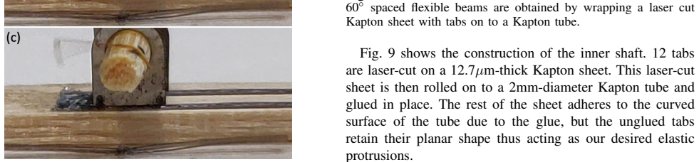
- [Section III.A and Section III.B] The statement that the robot 'can jump 6 times per minute each time landing perfectly on its feet' is established only for the tethered configuration; Section III.B reports that the untethered robot tips over after landing. Please make the domain of the landing claim explicit.
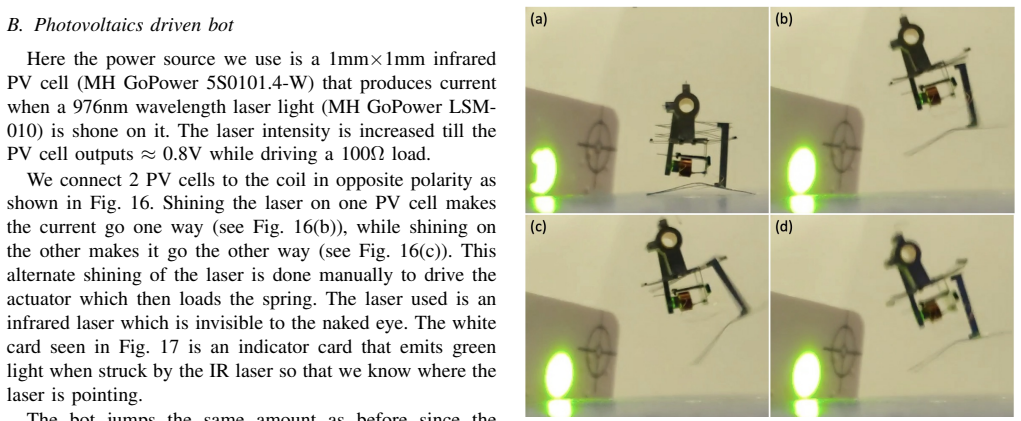
- [Figure 15 caption] The caption lists (a) before take-off, (c) highest position, and (d) feet touchdown, but no (b); please check the panel numbering.
- [Section II.E.2] The sentence 'resulting in the shaft adding adding up all the clockwise motions' contains a duplicated word and is awkwardly phrased; please revise.
- [Section II.G] The phrase 'torques need to be overcomed' should be 'torques need to be overcome.'
Circularity Check
No circularity in the mechanism derivation; the only quirks are non-load-bearing self-citations and a definitional ambiguity in the 'lightest' record claim.
full rationale
The design chain is self-contained. Spring stiffness and deflection are chosen from the measured magnet release force (F_release = 7.5 mN), giving 11.25 µJ stored energy; the predicted jump height is then obtained from energy conservation (15 mm) and compared to the measured 8 mm, so the observed height is a free output rather than a fitted target. The actuator sizing uses the same measured release force, assumed friction, shaft radius, moment-arm length, and an FEA-computed field to obtain I_coil ≈ 8 mA and 6.4 mW; the required torque is checked against an independent experimental torque threshold (17 µNm) rather than back-fit from the jump. The tethered/un-tethered jump comparison is an inference from added mass (<3 mg), not a circular parameter. The ratchet is described in enough detail in the present paper that the self-citation to [11] is not load-bearing, and the electronics-unit citation to [11] is future work. The abstract's 'lightest ... with onboard power source' claim is sensitive to whether the two PV cells qualify as an onboard power source (the conclusions use that phrase for a micro-cell/supercapacitor), but this is a definitional/reporting weakness in a record claim, not a circular derivation. No equation or fitted parameter is used to force the claimed result.
Assumptions & free parameters
free parameters (3)
- Spring stiffness k =
2.5 N/m
- Average magnetic field Bavg =
≈0.1 T
- Static friction coefficient µs =
1
assumptions (5)
- standard math Energy conservation for the jump: 1/2 k∆l^2 = mgh, neglecting air resistance.
- domain assumption Two anti-parallel magnets release suddenly when the opposing spring force exceeds the magnetic attraction.
- domain assumption In the ratchet, reverse rotation is locked because the elastic beams buckle and require orders of magnitude higher torque.
- ad hoc to paper The untethered bot jumps the same height as the tethered bot because the added PV mass (<3mg) is negligible.
- ad hoc to paper The elasticity of the two external wires provides stability in the tethered jumps.
Cite this review
Pith. "Pith review of An Insect-scale Untethered Laser-powered Jumping Microrobot." pith.science (2026). https://pith.science/paper/WO57M5V3
@misc{pith2026190803282,
  author       = {Pith},
  title        = {Pith review of: An Insect-scale Untethered Laser-powered Jumping Microrobot},
  year         = {2026},
  howpublished = {\url{https://pith.science/paper/WO57M5V3}},
  note         = {Machine review of arXiv:1908.03282}
}
abstract
We present the design of an insect-sized jumping microrobot measuring 17mm$\times$6mm$\times$14mm and weighing 75 milligrams. The microrobot consumes 6.4mW of power to jump up by 8mm in height. The tethered version of the robot can jump 6 times per minute each time landing perfectly on its feet. The untethered version of the robot is powered using onboard photovoltaic cells illuminated by an external infrared laser source. It is, to the best of our knowledge, the lightest untethered jumping microrobot with onboard power source that has been reported yet.
Figures


Figures from the paper (11 more)





Reference graph
Works this paper leans on
-
[8]
J. Greenspun and K.S.J. Pister, ``First leaps of an electrostatic inchworm motor-driven jumping microrobot,'' Hilton Head Solid-State Sensors, Actuators, and Microsystems Workshop , Hilton Head Island, SC, June 2018
work page 2018
-
[11]
[Under review] P. Bhushan and C.J. Tomlin, ``An Insect-scale Self-sufficient Rolling Microrobot,'' submitted to Robotics and Automation Letters (RA-L) 2019
work page 2019
-
[5]
W.A. Churaman, A. P. Gerratt and S. Bergbreiter, ``First leaps toward jumping microrobots,'' IROS , San Francisco, CA, USA, Sept. 2011
work page 2011
-
[1]
S. Bergbreiter, ``Effective and efficient locomotion for millimeter-sized microrobots,'' IROS , Nice, France, Sept. 2008
work page 2008
-
[2]
M. Karpelson, G-Y. Wei, and R.J. Wood, ``A Review of Actuation and Power Electronics Options for Flapping-Wing Robotic Insects,'' IEEE Int. Conf. on Robotics and Automation , Pasadena, CA, May 2008
work page 2008
-
[3]
James, V
J. James, V. Iyer, Y. Chukewad, S. Gollakota, and S.B. Fuller, ``'Liftoff of a 190 mg Laser-Powered Aerial Vehicle: The Lightest Untethered Robot to Fly,'' IEEE Int. Conf. on Robotics and Automation , Brisbane, Australia, May 2018
2018
-
[4]
Jafferis, E.F
N.T. Jafferis, E.F. Helbling, M. Karpelson, and R.J. Wood, ``Untethered Flight of an Insect-Sized Flapping-Wing Microscale Aerial Vehicle,'' Nature 570, 491-495, 2019
2019
-
[6]
W.A. Churaman, L.J. Currano, C.J. Morris, J.E. Rajkowski, S. Bergbreiter, ``The first launch of an autonomous thrust-driven microrobot using nanoporous energetic silicon,'' J. Microelectromech. Syst. 21: 198–205, 2012
work page 2012
Show all 12 references
-
[7]
J. Koh, S. Jung, R.J. Wood, K. Cho, ``A Jumping Robotic Insect Based on a Torque Reversal Catapult Mechanism,'' IROS , Tokyo, Japan, Nov. 2013
2013
-
[9]
Bhushan and C.J
P. Bhushan and C.J. Tomlin, ``Milligram-scale Micro Aerial Vehicle Design for Low-voltage Operation,'' IROS , Madrid, Spain, Oct. 2018
2018
-
[10]
Bhushan and C.J
P. Bhushan and C.J. Tomlin, ``Design of the first sub-milligram flapping wing aerial vehicle,'' MEMS , Seoul, South Korea, Jan. 2019
2019
-
[12]
" id="W5M0MpCehiHzreSzNTczkc9d
11em plus .33em minus .07em @technote 4000 4000 100 4000 4000 500 `\.=1000 = #1 #1 #1 0pt [0pt][0pt] #1 * \| ** #1 \@IEEEauthorblockNstyle \@IEEEauthorblockAstyle \@IEEEauthordefaulttextstyle \@IEEEauthorblockconfadjspace -0.25em \@IEEEauthorblockNtopspace 0.0ex \@IEEEauthorbl...
1999
Reviewed August 14, 2026 · model on record in the stance chip above.
Discussion (0). Continue with ORCID to comment.