REVIEW 3 major objections 4 minor 1 cited by
Onset of wavenumber bandgaps via alternating Willis coupling signs
T0 review · 3 major / 4 minor · reviewed 2026-08-12 · deepseek-v4-flash
Pith's one-line read Periodic sign-flips of a wave-bias term create wavenumber bandgaps in an elastic rod.
desk verdict The algebra is right, but the headline claim is wrong: the 'wavenumber bandgap' is a temporal instability, not a passive stop band. read the letter →
The pith
A machine-rendered reading of the paper's core claim, the machinery that carries it, and where it could break.
The reading
What carries the argument
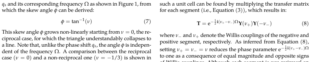
The load-bearing tool is the transfer matrix of the unit cell, obtained by multiplying the transfer matrices of the two half-cells, each of normalized length $\xi=1/2$. Because the Willis couplings of the two halves are equal in magnitude and opposite in sign, the exponential phase factor $e^{-\frac{i}{2}(\nu_+-\nu_-)\Omega}$ reduces to $1$, so the product becomes $T = Y(\nu)Y(-\nu)$, a $2\times 2$ matrix of unit determinant. The dispersion relation follows from writing the eigenvalues as $\lambda = e^{iq}$ and solving $\det(T-\lambda I)=0$, which yields the cosine relation for $q$. The bandgap limits are then read directly from the argument of the inverse cosine, and the width formula follows by subtraction. The paper uses the same transfer-matrix setting to derive the skew angle $\phi=\tan^{-1}\nu$ of the single-layer non-reciprocal dispersion, showing that the alternation removes this skew entirely.
What would settle it
Measure the driven-wave dispersion of a rod whose unit cell alternates between $+\nu$ and $-\nu$ Willis coupling segments (for example, via feedback controllers or moving segments) and check whether a stop band in wavenumber appears around $q=\pm\pi$ at frequencies $\Omega=(2p-1)\pi$ for $|\nu|>0$; absence of that gap would contradict Equation (9). A simpler numerical check is to integrate Equation (1) with piecewise-constant $\nu(x)$ and compare the Bloch wavenumber to the closed-form relation.
Extended reading notes
Core claim
The paper's central claim is that a unit cell made of two identical elastic layers with equal-magnitude, opposite-sign Willis couplings has the reciprocal driven-wave dispersion relation $q = \pm \cos^{-1}\left(\nu^2 + (1-\nu^2)\cos\Omega\right)$, so that wavenumber bandgaps open at odd multiples of $q=\pm\pi$ for every $\nu\neq 0$. The lower and upper limits of the $n$-th gap are $q_- = \pm[2(n-1)\pi + \cos^{-1}(2\nu^2-1)]$ and $q_+ = \pm[2n\pi - \cos^{-1}(2\nu^2-1)]$, giving the identical width $\Delta q = 2(\pi-\cos^{-1}(2\nu^2-1))$, which grows with $|\nu|$ and reaches $2\pi$ as $\nu\to 1$. The overall band structure is reciprocal even though each constitutive layer is non-reciprocal, and it is insensitive to the sign of $\nu$. The paper also finds that complex frequencies appear inside the wavenumber gaps and that the formulas are numerically confirmed by finite-element simulations. It closes by drawing a formal analogy between this design and bi-layered phononic crystals with zero frequency contrast and nonzero impedance contrast, identifying $\nu$ with the impedance contrast $\beta$ and $q$ with $\Omega$.
Load-bearing premise
The result holds only if a medium can actually be built in which the Willis coupling alternates in sign from one half of the unit cell to the next while density and stiffness stay constant; the paper defers such a realization to feedback-controlled designs, so the predicted gaps may not exist in any currently available passive material.
Editorial extensions
If this is right
- Wavenumber bandgaps become achievable with a purely static spatial pattern, without damping, temporal modulation, or complex spatiotemporal stiffness functions.
- Each half of the unit cell is non-reciprocal, yet the assembled cell is reciprocal; this offers a route to cancel non-reciprocity locally while keeping a gap.
- The gap width is controlled by the single parameter $\nu$ and saturates at the full Brillouin-zone width $2\pi$ in the limit $\nu\to 1$.
- The analytical limits and width match finite-element simulations, so the formulas can be used directly for design.
- The formal mapping to bi-layered phononic crystals implies that the same mathematics governs frequency gaps from impedance contrast and wavenumber gaps from Willis-sign alternation.
Reading between the lines
- If the analogy to bi-layered phononic crystals is more than formal, the wavenumber gap should close continuously as $\nu\to 0$ with a square-root-like scaling, a behavior a transmission experiment on a finite stack could test.
- The same sign-alternation idea might transfer to other momentum-biased wave systems (gyroscopic, rotating, or magneto-elastic), where a piecewise-constant bias of opposite signs could open wavenumber gaps without temporal modulation.
- Since each half is non-reciprocal but the unit cell is reciprocal, inserting a defect that reverses the alternation pattern might create a localized mode with net non-reciprocal response; this is an extension the paper does not explore.
- A lumped-parameter analog of Equations (9)-(11) could be built from a Willis monatomic lattice with alternating coupling signs, making the mechanism testable in a tabletop experiment.
Signed reviews
Editorial analysis
A structured set of objections, weighed in public.
Referee Report
Summary. The paper studies a one-dimensional Willis-type (axially moving rod) wave equation and shows that a unit cell made of two identical segments with equal-magnitude, opposite-sign Willis coupling yields the reciprocal dispersion relation q = ± arccos(ν² + (1−ν²) cos Ω), Eq. (9). The author derives explicit lower and upper limits of the resulting wavenumber gaps, Eqs. (10a)-(10b), and their width, Eq. (11), draws a formal analogy to frequency bandgaps of a special bi-layered phononic crystal, and reports finite-element verification. The algebraic derivation is transparent and parameter-free, with the expected limit ν=0 recovering the linear reciprocal dispersion.
Significance. If the result is correctly interpreted, it provides a clean, exactly solvable example of complex-frequency bands in a periodic Willis-type medium, which could be of interest for active metamaterial designs. The derivation is self-contained and does not rely on fitted parameters or opaque numerics. However, the central physical interpretation is currently misleading: the predicted 'wavenumber bandgaps' are in fact temporal instability bands, not passive stop bands. The paper explicitly notes that complex frequencies appear, but it does not state that one of the conjugate pair has a positive imaginary part, nor does it reconcile this with the claim of a bandgap. A revision that reframes the phenomenon as an instability/complex-frequency band and adds a stability analysis would make the contribution sound and publishable.
major comments (3)
- [Elastic rod with periodic Willis coupling, Eq. (9) and Fig. 3] The claimed 'wavenumber bandgap' is a temporal instability, not a passive stop band. For any real q inside the gap, Eq. (9) implies cos Ω = (cos q − ν²)/(1−ν²) < −1, so Ω = π ± iα with α > 0. Since the underlying PDE is real, the two signs form a conjugate pair, and the solution with positive imaginary part grows exponentially in time as e^{ατ}. By contrast, for any real driving frequency Ω, the right-hand side of Eq. (9) lies in [2ν²−1, 1], so q is always real and no frequency is suppressed. The paper's statement that 'complex frequencies emerge in wavenumber bandgap' stops short of noting the positive imaginary part. The footnote on page 1 restricting ν to [0,1) 'to avoid possible dynamical instabilities' is therefore in direct tension with the phenomenon presented. The central claim should be revised to state that the configuration produces instability bands, with a stability analysis.
- [Elastic rod with periodic Willis coupling, Eqs. (6) and (9)] The label 'driven-wave dispersion relation' for Eq. (9) is misleading. When Ω is real (the usual driven situation), Eq. (9) gives real q for all Ω; the complex frequencies appear only if one instead fixes a real q and solves for Ω, which is an eigenvalue/initial-value problem. The manuscript does not distinguish these two settings. This distinction is load-bearing because it determines whether the gap acts as a filter for real-frequency excitation (it does not) or as an instability band for real-wavenumber perturbations (it does). Please clarify the problem statement and the meaning of 'driven' in this context.
- [Similarities between reversed-sign Willis couplings and bi-layered periodicity, Table 1] The analogy in Table 1 is formal rather than physical. In a bi-layered phononic crystal, a frequency bandgap is a range of real frequencies with no real wavenumber, and the corresponding Floquet exponent is complex, giving spatial evanescence. Here, the 'wavenumber bandgap' is a range of real wavenumbers with no real frequency, and the corresponding temporal frequency is complex, giving temporal growth. These are dual in a purely algebraic sense, but their physical consequences are opposite: spatial decay versus temporal instability. The paper should explicitly discuss this difference before claiming equivalence of the roles of ν and β.
minor comments (4)
- [Fig. 3 and 'finite element method' statement] The finite-element verification is stated but not documented: no mesh parameters, element type, boundary conditions, or error metrics are given, and the procedure used to obtain complex-frequency branches is not described. Since the analytic derivation is central and convincing, this is a reproducibility issue rather than a scientific flaw, but the details should be provided or a reference given.
- [Eq. (8) and notation] In Eq. (8), the notation ν+ and ν− is ambiguous: it is not immediately clear that these are magnitudes of the signed couplings rather than signed values. Please define them explicitly, e.g., as positive magnitudes, so that 'setting ν+ = ν− = ν' cannot be misread as both segments having the same sign.
- [Fig. 3] The 'Real Imag.' inset in Fig. 3 is difficult to read. It would help to label the branches with positive and negative imaginary parts explicitly and to state in the caption that the positive-imaginary branch corresponds to temporal growth.
- [Introduction, Eq. (2)] The nondimensionalization that leads from Eq. (1) to Eq. (2) is correct but terse; showing the cancellation of the ω0 and c factors would make the derivation easier to follow for readers not familiar with the cited references.
Circularity Check
No circularity; the derivation of Eq. (9) is self-contained, and the self-citations are contextual rather than load-bearing.
full rationale
The central dispersion relation (Eq. 9) is derived directly from the non-dimensional Willis-type wave equation (Eq. 2) via a standard transfer-matrix product for two equal-length segments with opposite coupling signs. No free parameters are fitted: the normalized modulation speed ν is a preselected model parameter swept analytically, and the bandgap limits and width (Eqs. 10-11) are exact consequences of Eq. 9. The prior self-citations are not load-bearing: Ref. [5] is invoked only as a 'reminiscent' remark about a phase shift in a monatomic lattice, and Ref. [8] is used in Table 1 as an analogy to bi-layered phononic crystals, not as a premise for the bandgap derivation. The statement that 'complex frequencies emerge in wavenumber bandgap [28]' also does not feed back into Eq. 9, which already implies complex frequency solutions for real q in the gap. Whether this should be called a bandgap or an instability band is a physical-interpretation concern, not circularity.
Assumptions & free parameters
assumptions (3)
- domain assumption Equation (1), the axially moving rod equation, is a valid Willis-type equation of motion with v0 as the Willis coupling coefficient.
- standard math The transfer matrix method with Floquet-Bloch periodic boundary conditions applies, and displacement and internal force are continuous at segment interfaces.
- domain assumption The unit cell consists of exactly two equal-length segments with equal and opposite Willis coupling signs.
Cite this review
Pith. "Pith review of Onset of wavenumber bandgaps via alternating Willis coupling signs." pith.science (2026). https://pith.science/paper/X543IBKL
@misc{pith2026241206798,
  author       = {Pith},
  title        = {Pith review of: Onset of wavenumber bandgaps via alternating Willis coupling signs},
  year         = {2026},
  howpublished = {\url{https://pith.science/paper/X543IBKL}},
  note         = {Machine review of arXiv:2412.06798}
}
read the original abstract
This article introduces a methodology for inducing wavenumber bandgaps via alternating Willis coupling signs. A non-reciprocal wave equation of Willis-type is first considered, and its wave dispersion analyses are carried out via the transfer matrix method. By creating unit cells from two identical Willis-type elastic layers, yet with reversed Willis-coupling signs, a reciprocal band structure peculiarly emerges, although each layer exhibits non-reciprocity if considered individually. Wavenumber bandgaps open due to such unit cell configuration, and their width and limits are analytically quantified. Similarities between materials with reversed-sign Willis coupling and bi-layered phononic crystals are noted, followed by concluding remarks.
Figures


Forward citations
Cited by 1 Pith paper
-
Observation of dispersion anomalies by design
Negative stiffness plus ground stiffness tunes phonon dispersion to hit zero frequency at chosen wavenumbers, opening passive wavenumber band gaps demonstrated in 1D and 2D magnetic lattices.
Reference graph
Works this paper leans on
-
[1]
to avoid possible dynamical instabilities [1]. 1 arXiv:2412.06798v2 [physics.optics] 23 Mar 2025 qs and its corresponding frequencyΩ as shown in Figure 1, from which the skew angle ϕ can be derived: ϕ = tan−1(ν) (7) This skew angleϕ grows non-linearly starting fromν = 0, the re- ciprocal case, for which the triangle understandably collapses to a line. Not...
arXiv 2025
-
[2]
with special modula- tion parameters is noticed. It has been recently shown that identi- cal frequency bandgaps in phononic crystals open with perfect pe- riodicity along thefrequency axis by satisfying two conditions [8]: • A zero frequency contrast, achieved via setting ℓ1c2 = ℓ2c1, and • A non-zero characteristic impedance contrast β = (z1 − z2)/(z1 + ...
work page 2018
Reviewed August 12, 2026 · model on record in the stance chip above.
Discussion (0). Continue with ORCID to comment.