REVIEW 3 major objections 6 minor 42 references
Reconfigurable sub-micron spin-wave majority gate with electrical transducers
T0 review · 3 major / 6 minor · reviewed 2026-08-14 · deepseek-v4-flash
Pith's one-line read An inline spin-wave majority gate with three equally spaced electrical antennas computes the majority of three phase-encoded inputs by wave interference, demonstrated in an 850-nm-wide CoFeB waveguide.
desk verdict A genuine experimental step forward in spin-wave majority logic, but the all-electrical truth table needs an explicit spin-wave amplitude-balance check to rule out a weighted vote. read the letter →
The pith
A machine-rendered reading of the paper's core claim, the machinery that carries it, and where it could break.
The reading
What carries the argument
The device is the inline spin-wave majority gate: input and output transducers placed at equally spaced positions $n\times 2F$ along a waveguide, with $F$ smaller than the spin-wave attenuation length. Logic 0 and 1 are spin-wave phases $0$ and $\pi$, and the output is the phase of the coherent sum of the three waves. The load-bearing condition is resonant operation, $2F = N\lambda$, which makes identical microwave input phases arrive in phase at the output; the phase-sensitive readout extracts the output phase from the bias-field derivative of the microwave transmission parameter.
What would settle it
Repeat the eight input-phase combinations while attenuating one input antenna by a known amount, for example 3 dB; if the output phase ever follows the weakened input's phase instead of the majority of the three phases, the equal-amplitude premise is violated and the gate is not robust to realistic path imbalance.
Extended reading notes
Core claim
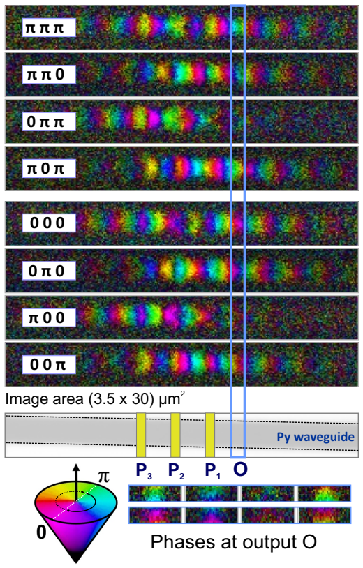
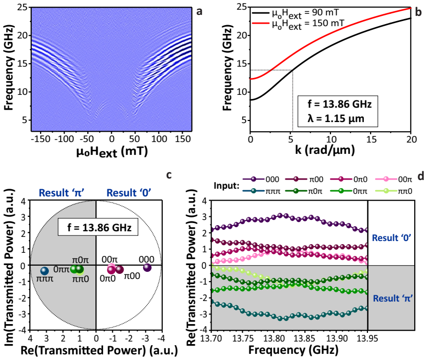
The central discovery is that a straight ferromagnetic waveguide with three equally spaced inductive input antennas and an output antenna acts as a majority gate when information is encoded in spin-wave phase. Because each input-to-output distance is a multiple of the spin-wave wavelength under resonant operation, the three coherent spin waves arrive at the output with aligned phases, so the phase of their superposition is the majority phase. The paper verifies this by reconstructing all eight rows of the majority truth table from phase-sensitive all-electrical measurements at sub-micrometre scale, and by time-resolved X-ray imaging of a wider permalloy device. The same inline geometry also yields reconfigurable inputs and outputs, fan-out of two, frequency-division multiplexing, and a minority function at a detuned frequency.
Load-bearing premise
The all-electrical truth table assumes the three spin-wave contributions arriving at the output have nearly equal amplitudes; the measurement equalises only the microwave amplitudes sent to the three input antennas, not the spin-wave transmission amplitude of each input-to-output path.
Editorial extensions
If this is right
- The inline gate occupies $16F^2$ ($20F^2$ with a fan-out of two), far below the roughly $330F^2$ area of a CMOS majority gate, so phase-based magnonic logic becomes area-competitive if the scaling holds.
- Because any port can be selected as the output, one fabricated device can be reprogrammed for different logic functions without changing the layout, demonstrated on a 4.7-µm-wide waveguide.
- Resonant operation at two harmonics means the same gate can compute independently in two frequency channels at once, raising throughput without extra area.
- A detuned frequency gives the minority function in the same device, so combining the majority gate with a $\pi$ phase shift (inverter) yields a functionally complete logic set.
- The truth table is also obtained at a 600-nm spin-wave wavelength, showing the interference mechanism survives at the sub-micrometre length scales needed for dense integration.
Reading between the lines
- The equal-amplitude caveat points to a direct stress test: calibrate each input-to-output spin-wave transmission separately and check whether the truth table survives a deliberate 3 dB imbalance.
- The same resonant-interference argument should extend to more than three inputs by adding transducers at further multiples of $2F$; the paper mentions this possibility but does not test it.
- If frequency-division multiplexing holds at higher power, two simultaneous tone sets on the same waveguide should yield two independent majority outputs that can be demodulated separately; that experiment would confirm true parallel computation.
- The nonreciprocity of inductive excitation in the transverse-field geometry leaves the backward fan-out arm with a weaker signal; a natural follow-up is to test whether forward-volume spin waves or nonchiral transducers make fan-out symmetric.
Signed reviews
Editorial analysis
A structured set of objections, weighed in public.
Referee Report
Summary. The manuscript reports an inline spin-wave majority gate implemented in CoFeB and permalloy waveguides with inductive microwave antennas. Logic is encoded in the phase (0 or pi) of spin waves launched by three input ports, and the output phase is read at a fourth port. The authors present time-resolved scanning transmission x-ray microscopy (STXM) imaging of the spin-wave interference in a 2.0-um-wide permalloy waveguide, showing the full majority truth table, and all-electrical vector-network-analyzer measurements in 850-nm-wide and 4.7-um-wide CoFeB waveguides. The all-electrical experiments demonstrate majority operation, reconfigurable output ports, frequency-division multiplexing at N=1 and N=2 resonances, and a minority function at a detuned frequency. The paper also discusses area scaling (16F^2), fan-out, and the potential for a spin-wave-based computing platform.
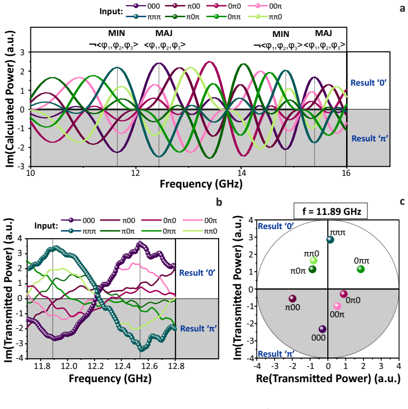
Significance. If the claims are fully substantiated, this is a significant advance over earlier millimeter-scale YIG trident gates: it moves to metallic waveguides with sub-micron width and wavelength, all-electrical readout, and demonstrates two logic functions (majority and minority) in a single device. The minority-function prediction at 11.89 GHz is a concrete falsifiable test that is confirmed experimentally, and the STXM images directly reveal the spin-wave interference pattern behind the majority operation. The main caveat is that the all-electrical sub-micron truth table depends on an unstated premise of equal spin-wave amplitudes from the three input paths, which is not explicitly calibrated in the manuscript.
major comments (3)
- [Methods - All-electrical microwave measurements] The equalization of microwave amplitudes at the input ports does not guarantee equal spin-wave amplitudes at the output. The three paths from P1, P2, and P3 to the output port O have lengths 6F, 4F, and 2F, so propagation losses and any antenna or mode-conversion asymmetry make the output amplitudes A1, A2, and A3 differ. For phase-coded interference, the output is A1 exp(i*phi1) + A2 exp(i*phi2) + A3 exp(i*phi3); if one amplitude exceeds the sum of the other two, the phase of the sum can follow a minority input rather than the majority (for example, if A3 > A1+A2, the input (0,0,pi) yields an output phase of pi instead of 0, and if A1 > A2+A3, the input (0,pi,pi) yields 0 instead of pi). The manuscript does not report per-path spin-wave transmission calibrations (such as single-input measurements at each port) or a robustness check against amplitude mismatch. Since the sub-micron all-electrical claims in Figs. 3 and 5 rest on this premise, this is a load-bearing point that needs to be addressed.
- [Electrical operation of nanoscale spin-wave majority gates (Figs. 3c,d) and Frequency-division multiplexing (Figs. 5c-e)] The all-electrical truth tables are extracted from S21 measurements, but the paper does not describe any subtraction of the electromagnetic crosstalk baseline between the input and output antennas. The manuscript mentions that U-shaped antennas were chosen for their low parasitic crosstalk, but no control measurement without propagating spin waves (e.g., at a magnetic field above saturation or with no excitation) is shown. A field-independent crosstalk contribution would add a constant phasor to the coherent output and could shift the extracted phase for weak-majority states, potentially making the truth-table separation less meaningful. Please provide a control experiment or clearly describe how crosstalk was excluded from the phase analysis.
- [Abstract and Time-resolved imaging of spin-wave majority gate operation] The abstract lists fan-out as a key feature of the device, but the fan-out-of-two claim is inferred from the bidirectional spin-wave propagation visible in the STXM images (Fig. 2) and from the symmetry of the geometry, not from a direct demonstration of simultaneous readout at two output ports. To substantiate the fan-out claim, the authors should either show an all-electrical or STXM measurement with two output ports read concurrently, or soften the wording to 'bidirectional propagation, which enables fan-out in principle.' This distinction matters because the abstract explicitly promises a demonstrated fan-out.
minor comments (6)
- [Main text, page 8] The sentence 'contributions from backward-volume spin wave modes are also are also visible' contains a duplicated phrase; please correct it.
- [Fig. 4] The claim that the majority gate 'works equally well' in the two port configurations is based on visual inspection of the frequency traces; a quantitative comparison of the separation between the '0' and 'pi' clusters (e.g., the minimum distance between the two sets of curves) would be more convincing.
- [Methods - All-electrical microwave measurements] Please specify the calibration procedure and accuracy of the delay-based phase shifters, and state how the phase at each port was set and verified at the target frequencies.
- [References] Reference [41] contains a punctuation error: 'Liu, X., Zhang, W. Carter, M.J. & Xiao, G.' should read 'Liu, X., Zhang, W., Carter, M.J. & Xiao, G.'
- [Operation principle and Implementation sections] The stated gate area of 16F^2 (20F^2 with fan-out) counts only the active waveguide region, not the transducers, feedlines, and contact pads; please clarify this in the area comparison with CMOS majority gates.
- [Reconfigurability section] The term 'reconfigurable input and output ports' is used to describe experiments that select among fixed physical ports, not runtime reconfiguration; please adjust the wording to avoid implying dynamic reprogrammability.
Circularity Check
No circularity: the majority truth table is measured directly and the minority operation at a detuned frequency is an independent prediction from the measured dispersion, confirmed experimentally.
full rationale
The central claims are experimental demonstrations, not derivations from fitted parameters. The full majority truth table is reconstructed from STXM phase maps (Fig. 2) and from all-electrical S21 measurements (Figs. 3c-d), not computed from any model output. The dispersion relation used to select resonant frequencies is extracted from separate two-port spin-wave transmission measurements and is not fitted to the logic outputs. The minority (MIN) operation at 11.89 GHz is a genuine prediction: the paper specifies the phase-accumulation condition 2πN ± π/4 and then verifies the resulting truth table experimentally. The only in-text self-citation, ref. [26], supplies the inline gate layout with ports at n×2F positions; it is not used to justify the logic behavior or to exclude alternatives, and it is independently published experimental work. The concern about equalizing input microwave amplitudes rather than per-path spin-wave transmission amplitudes is a measurement premise or correctness risk, not a circularity: no fitted parameter is renamed as a prediction, and no output quantity is defined in terms of the claimed result.
Assumptions & free parameters
assumptions (4)
- domain assumption Logic 0 and 1 are encoded as spin wave phases 0 and pi, and the majority function is obtained by linear superposition of coherent spin waves.
- domain assumption The bias-field derivative of the microwave S21 parameter isolates the propagating spin wave signal from direct electromagnetic crosstalk.
- domain assumption Resonant operation, where the interport distance equals an integer multiple of the spin wave wavelength (2F = N*lambda), makes all input phases arrive matched at the output.
- domain assumption The three spin wave contributions at the output have approximately equal amplitudes so that their sum phase equals the majority phase.
Cite this review
Pith. "Pith review of Reconfigurable sub-micron spin-wave majority gate with electrical transducers." pith.science (2026). https://pith.science/paper/XQNINZ5N
@misc{pith2026190802546,
  author       = {Pith},
  title        = {Pith review of: Reconfigurable sub-micron spin-wave majority gate with electrical transducers},
  year         = {2026},
  howpublished = {\url{https://pith.science/paper/XQNINZ5N}},
  note         = {Machine review of arXiv:1908.02546}
}
read the original abstract
Spin waves are excitations in ferromagnetic media that have been proposed as information carriers in hybrid spintronic devices with much lower operation power than conventional charge-based electronics. Their wave nature can be exploited in majority gates by using interference for computation. However, a scalable spin-wave majority gate that can be co-integrated alongside conventional electronics is still lacking. Here, we demonstrate a sub-micron inline spin-wave majority gate with fan-out. Time-resolved imaging of the magnetization dynamics by scanning transmission x-ray microscopy illustrates the device operation. All-electrical spin-wave spectroscopy further demonstrates majority gates with sub-micron dimensions, reconfigurable input and output ports, and frequency-division multiplexing. Challenges for hybrid spintronic computing systems based on spin-wave majority gates are discussed.
Figures

Figures from the paper (3 more)


Reference graph
Works this paper leans on
-
[1]
Kajiwara, Y.et al.Transmission of electrical signals by spin-wave interconversion in a magnetic insulator. Nature 464, 262–266 (2010)
work page 2010
-
[2]
Sander, D.et al.The 2017 magnetism roadmap.J. Phys. D: Appl. Phys.50, 363001 (2017)
work page 2017
-
[3]
Lenk, B., Ulrichs, H., Garbs, F. & Münzenberg, M. The building blocks of magnonics.Phys. Rep.507, 107–136 (2011)
work page 2011
-
[4]
As shown in Fig. 6a, the imaginary part of the output signal then leads to the minority (majority) function of the inputs at the corresponding frequency below (above) the resonant one. This is experimentally confirmed in a spin wave majority gate with a 4.7-µm-wide Co40Fe40B20 waveguide, a magnetic bias field ofµ0Hext = 42 mT, and an interport spacing of 2....
work page 2020
-
[5]
Chumak, A.V., Vasyuchka, V.I., Serga, A.A. & Hillebrands, B. Magnon spintronics.Nature Phys. 11, 453–461 (2015)
work page 2015
-
[6]
Cornelissen, L.J., Liu, J., Duine, R.A., Youssef, J.B. & van Wees, B.J. Long-distance transport of magnon spin information in a magnetic insulator at room temperature.Nature Phys.11, 1022–1026 (2015)
work page 2015
-
[7]
Haldar, A., Kumar, F. & Adeyeye, A.O. A reconfigurable waveguide for energy-efficient trans- mission and local manipulation of information in a nanomagnetic device.Nature Nanotechnol. 11, 437–443 (2016)
work page 2016
-
[8]
Kim, J.-V., Stamps, R.L. & Camley, R.E. Spin wave power flow and caustics in ultrathin ferromagnets with the Dzyaloshinskii-Moriya interaction.Phys. Rev. Lett.117, 197204 (2016)
work page 2016
Show all 42 references
-
[9]
Adv.4, e1701517 (2018)
Wang, Q.et al.Reconfigurable nano-scale spin-wave directional coupler.Sci. Adv.4, e1701517 (2018)
2018
-
[10]
Sluka, V.et al.Emission and propagation of 1D and 2D spin waves with nanoscale wavelengths in anisotropic spin textures.Nature Nanotechnol.14, 328–333 (2019)
2019
-
[11]
Multi-frequency magnonic logic circuits for parallel data processing.J
Khitun, A. Multi-frequency magnonic logic circuits for parallel data processing.J. Appl. Phys. 111, 054307 (2012)
2012
-
[12]
Vogt, K.et al., Realization of a spin-wave multiplexer.Nature Commun.5, 3727 (2014)
2014
-
[13]
Awad, A.A. et al. Long-range mutual synchronization of spin Hall nano-oscillators.Nature Phys. 13, 292–299 (2017)
2017
-
[14]
& Wang, K.L
Khitun, A., Nikonov, D.E. & Wang, K.L. Magnetoelectric spin wave amplifier for spin wave logic circuits.J. Appl. Phys.106, 123909 (2009)
2009
-
[15]
Gladii, O. et al. Spin wave amplification using the spin Hall effect in permalloy/platinum 18 bilayers. Appl. Phys. Lett.108, 202407 (2016)
2016
-
[16]
Rovillain, P. et al. Electric-field control of spin waves at room temperature in multiferroic BiFeO3. Nature Mater.9, 975–979 (2010)
2010
-
[17]
& Hillebrands, B
Chumak, A.V., Serga, A.A. & Hillebrands, B. Magnon transistor for all-magnon data process- ing. Nature Commun.5, 4700 (2014)
2014
-
[18]
& Duine, R.A
Cornelissen, L.J., Liu, J., van Wees, B.J. & Duine, R.A. Spin-current-controlled modulation of the magnon spin conductance in a three-terminal magnon transistor.Phys. Rev. Lett.120, 097702 (2018)
2018
-
[19]
& van Dijken, S
Hämäläinen, S.J., Madami, M., Qin, H., Gubbiotti, G. & van Dijken, S. Control of spin-wave transmission by a programmable domain wall.Nature Commun.9, 4853 (2018)
2018
-
[20]
Balinskiy, M.et al.Magnetoelectric spin wave modulator based on synthetic multiferroic struc- ture. Sci. Rep.8, 10867 (2018)
2018
-
[21]
& Wang, K.L
Khitun A. & Wang, K.L. Non-volatile magnonic logic circuits engineering.J. Appl. Phys.110, 034306 (2011)
2011
-
[22]
Radu, I.P. et al. Spintronic majority gates. Proc. 2015 IEEE Intern. Electron Dev. Meet. (IEDM), 32.5 (2015)
2015
-
[23]
Zografos, O.et al.Non-volatile spin wave majority gate at the nanoscale.AIP Adv.7, 056020 (2017)
2017
-
[24]
Klingler, S.et al.Design of a spin-wave majority gate employing mode selection.Appl. Phys. Lett.105, 152410 (2014)
2014
-
[25]
Fischer, T.et al.Experimental prototype of a spin-wave majority gate.Appl. Phys. Lett.110, 152401 (2017)
2017
-
[26]
SPIE10962, 1096202 (2019)
Sherazi, S.M.Y.et al.Standard-cell design architecture options below 5 nm node: the ultimate scaling of FinFET and nanosheet,Proc. SPIE10962, 1096202 (2019)
2019
-
[27]
2018 IEEE Intern
Ciubotaru, F.et al.First experimental demonstration of a scalable linear majority gate based on spin waves,Proc. 2018 IEEE Intern. Electron Dev. Meet. (IEDM), 36.1 (2018)
2018
-
[28]
& Hillebrands, B
Serga, A.A., Chumak, A.V. & Hillebrands, B. YIG magnonics.J. Phys. D: Appl. Phys.43, 264002 (2010)
2010
-
[29]
Madami, M. et al. Direct observation of a propagating spin wave induced by spin-transfer torque. Nature Nanotechnol.6, 635–638 (2011)
2011
-
[30]
Cherepov, S.et al.Electric-field-induced spin wave generation using multiferroic magnetoelec- 19 tric cells.Appl. Phys. Lett.104, 082403 (2014)
2014
-
[31]
Collet, M.et al.Generation of coherent spin-wave modes in yttrium iron garnet microdiscs by spin-orbit torque.Nature Commun.7, 10377 (2016)
2016
-
[32]
Talmelli, G. et al. Spin-wave emission by spin-orbit-torque antennas.Phys. Rev. Appl. 10, 044060 (2018)
2018
-
[33]
& Bailleul, M
Vlaminck, V. & Bailleul, M. Spin-wave transduction at the submicrometer scale: experiment and modeling.Phys. Rev. B81, 014425 (2010)
2010
-
[34]
& Radu, I.P
Ciubotaru, F., Devolder, T., Manfrini, M., Adelmann, C. & Radu, I.P. All electrical propa- gating spin wave spectroscopy with broadband wavevector capability.Appl. Phys. Lett.109, 012403 (2016)
2016
-
[35]
& Damon, R.W
Eshbach, J.R. & Damon, R.W. Surface magnetostatic modes and surface spin waves.Phys. Rev.118, 1208–1210 (1960)
1960
-
[36]
Micromagnetic simulations of magnetoelastic spin wave excitation in scaled magnetic waveguides.Appl
Duflou, R.et al. Micromagnetic simulations of magnetoelastic spin wave excitation in scaled magnetic waveguides.Appl. Phys. Lett.111, 192411 (2017)
2017
-
[37]
Kalinikos, B.A.&Slavin, A.N.Theoryofdipole-exchangespinwavespectrumforferromagnetic films with mixed exchange boundary conditions,J. Phys. C: Solid State Phys.19, 7013–7033 (1986)
1986
-
[38]
Spin Wave Confinement: Propagating Waves(2nd edition, Pan Stanford Publishing, Singapore, 2017)
Demokritov, S.O. Spin Wave Confinement: Propagating Waves(2nd edition, Pan Stanford Publishing, Singapore, 2017)
2017
-
[39]
Nolle, D. et al. Note: unique characterization possibilities in the ultra high vacuum scan- ning transmission x-ray microscope (UHV-STXM) “MAXYMUS” using a rotatable permanent magnetic field up to 0.22 T.Rev. Sci. Instrum.83, 046112 (2012)
2012
-
[40]
Nanoscale detection of spin wave deflection angles in permalloy.Appl
Groß, F.et al. Nanoscale detection of spin wave deflection angles in permalloy.Appl. Phys. Lett.114, 012406 (2019)
2019
-
[41]
& Porter, D.G
Donahue, M.J. & Porter, D.G. Interagency Report NISTIR 6376, National Institute of Stan- dards and Technology, Gaithersburg, MD (1999)
1999
-
[42]
Carter, M.J
Liu, X., Zhang, W. Carter, M.J. & Xiao, G. Ferromagnetic resonance and damping properties of CoFeB thin films as free layers in MgO-based magnetic tunnel junctions.J. Appl. Phys. 110, 033910 (2011). 20
2011
Reviewed August 14, 2026 · model on record in the stance chip above.
Discussion (0). Continue with ORCID to comment.