REVIEW 2 major objections 5 minor 49 references
Calibration of cascaded phase shifters using pairwise scan method in silicon photonics integrated chip
T0 review · 2 major / 5 minor · reviewed 2026-08-11 · deepseek-v4-flash
Pith's one-line read Scanning phase shifters in pairs calibrates cascaded photonic chips to 99.97% fidelity.
desk verdict A real, working calibration method for cascaded phase shifters, with a clean derivation and a solid demo, but the unverified linearity assumption and the unbenchmarked 'rapid' claim need attention before I'd trust it for quantum-grade phase setting. read the letter →
The pith
A machine-rendered reading of the paper's core claim, the machinery that carries it, and where it could break.
The reading
What carries the argument
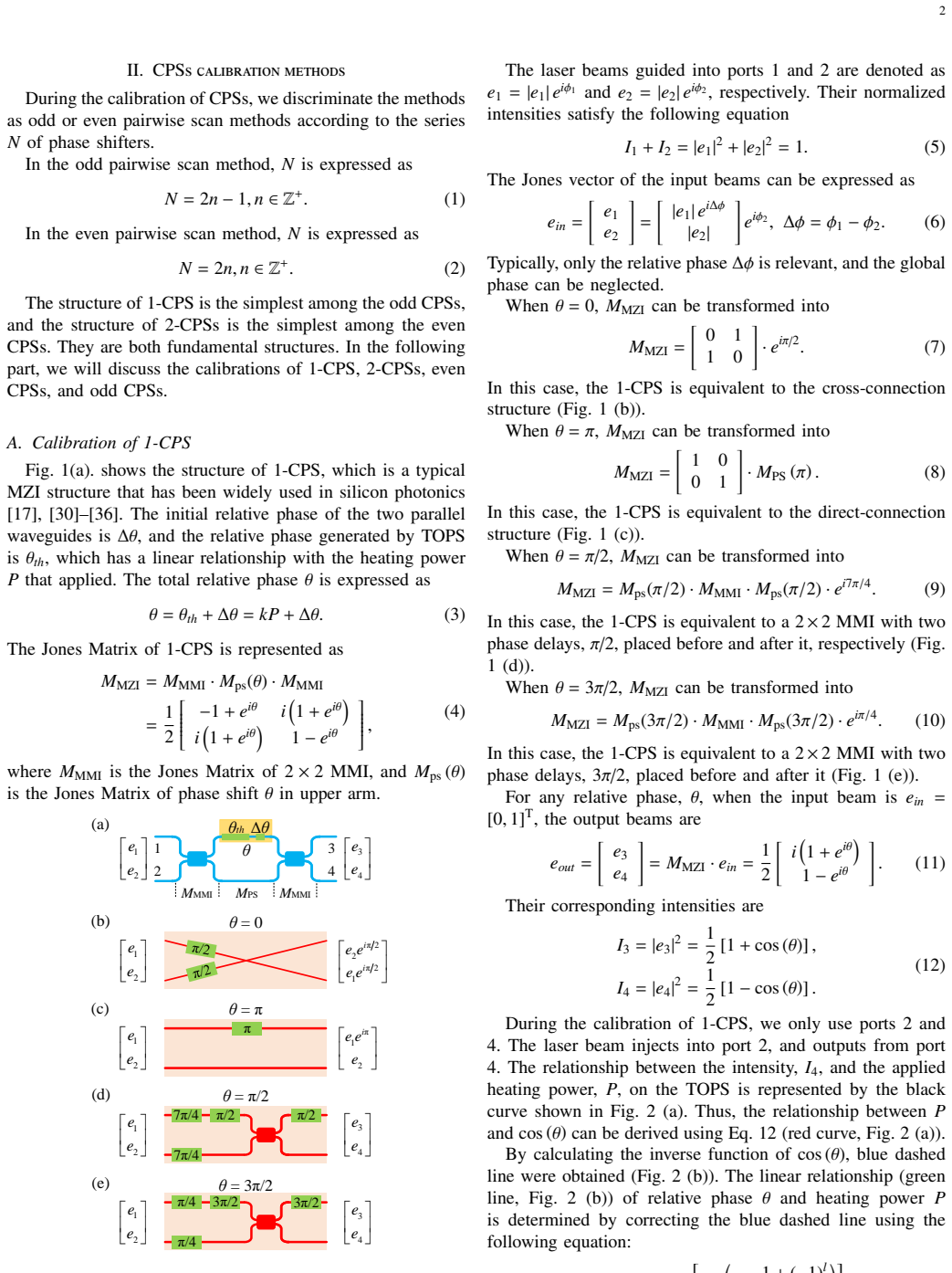
The load-bearing object is the equivalent-structure transform of a single Mach-Zehnder interferometer: when the total relative phase θ equals 0, π, π/2, or 3π/2, the MZI's Jones matrix collapses to a cross connection, a direct connection, or an MMI flanked by π/2 (or 3π/2) delays. Pairwise scanning uses these four equivalences to reduce a long CPS to a short chain: with the rightmost shifter parked at a minimum of the peak-to-peak intensity U_P=|c2 sin θ_{2n}|, its MZI becomes transparent (cross or direct), so the next pair can be calibrated identically; parking it at the maximum (θ=π/2) gives the sin/cos inversion needed to fit the neighbor's slope. The constraint |Δθ|<π/2 selects the correct branch of the inverse trigonometric unfolding, and the linear model θ=kP+Δθ turns the scan into a straight-line fit.
What would settle it
Measure output intensity from port 4 while ramping one TOPS over the full 0–10 V range at fine steps and compare the fitted linear phase θ=kP+Δθ against direct interferometric phase extraction at several powers (e.g., via a second MZI with known phase). A systematic residual above the reported step resolution of 1.7×10⁻² rad would falsify the linearity assumption on which the pairwise scan rests.
Extended reading notes
Core claim
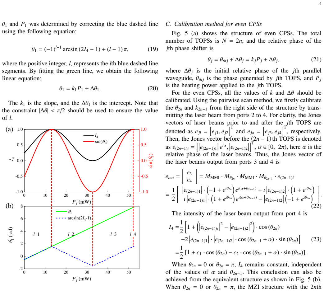
On the paper's own terms, the central claim is that every phase shifter in a cascaded phase-shifter structure can be calibrated from intensity measurements alone by scanning pairs of thermo-optic phase shifters stepwise, provided the initial relative phase of each arm satisfies the constraint |Δθ|<π/2. For a 1-CPS (one Mach-Zehnder interferometer), the relative phase θ=kP+Δθ is extracted by fitting the linear relation after unfolding arccos(1−2I4). For longer chains, scanning the (2n)th shifter while sweeping the (2n−1)th gives a peak-to-peak output U_P=|c2 sin θ_{2n}|, whose first maximum locates θ_{2n}=π/2 and whose first minimum locates θ_{2n}=0 or π; setting the shifter to that minimum makes its MZI equivalent to a cross or direct connection, so the next pair can be calibrated in the same way. Scanning from right to left and then left to right calibrates all slopes and initial phases; for odd N, applying the maximum-power point to the last shifter inserts a π/2 phase that makes the structure behave like the even case. The paper reports 99.97% average fidelity on a packaged 6-CPS chip and shows that its no-constraint variant (Appendices A and B) yields nearly identical initial phases.
Load-bearing premise
The method assumes that each thermo-optic phase shift is exactly linear in heating power, θ=kP+Δθ, over the whole scan range; if thermal crosstalk or high-power effects bend that line, the fitted slope and intercept will be wrong at operating points away from the scan data.
Editorial extensions
If this is right
- Calibration of an N-shifter CPS reduces to a sequence of pairwise scans plus linear fits, avoiding the exponential calculation of the traditional method and the more elaborate linear-scaling methods.
- Only one input port and one output port are required, so the method can be applied inside larger networks where only edge ports are accessible.
- For even N the right-to-left and left-to-right passes calibrate all slopes and all initial phases; for odd N, a π/2-equivalent transform of the last shifter extends the same procedure.
- A no-constraint variant (Appendices A and B) calibrates the same initial phases without |Δθ|<π/2, and on the 6-CPS chip its results agree with the constrained method.
- The measured 99.97% average fidelity (96.6% of points above 99.9%) suggests the scan-and-fit calibration is accurate enough for on-chip quantum information tasks.
Reading between the lines
- Editorial inference: because the method needs only two adjacent shifters at a time, it is naturally suited to in-situ recalibration during operation—warm-up drift of one shifter could be corrected by a local pairwise scan rather than a full-chip recalibration.
- Editorial inference: the same pairwise logic might be adapted to Reck and Clements meshes; the paper lists those networks as future work, and the equivalent-structure transform is a natural fit for their MZI building blocks.
- Editorial inference: the fidelity metric used here is based on classical output intensities; a quantum-process test (e.g., Hong-Ou-Mandel or two-photon interference visibility after calibration) would be a stronger end-to-end check of the method for quantum circuits.
- Editorial inference: the reported temperature dependence of the initial phase suggests that a single calibrated slope may remain valid across operating temperatures, so recalibration after temperature changes could update only the intercept, not the full pairwise scan.
Editorial analysis
A structured set of objections, weighed in public.
Referee Report
Summary. The paper proposes a pairwise scan method for calibrating cascaded phase shifters (CPSs) in silicon photonic integrated circuits. The method models each CPS as a sequence of 2x2 MMIs and thermo-optic phase shifters with a linear phase-power relation theta = kP + DeltaTheta, and it calibrates all parameters by nested scans of adjacent pairs, relying on equivalent MZI structures and a constraint |DeltaTheta| < pi/2. The authors also give a no-constraint variant, simulate TOPS and MMI designs to minimize thermal crosstalk and imbalance, and experimentally validate the method on a packaged 6-CPS chip, reporting an average intensity fidelity of 99.97%.
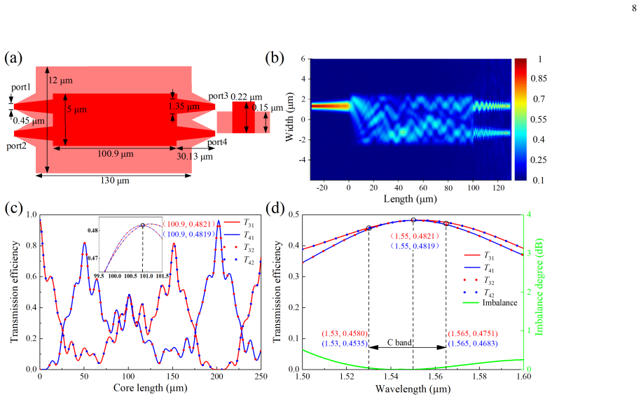
Significance. If the method holds, it provides a practical calibration protocol for quantum photonic circuits that uses only one input and one output port and requires minimal post-processing, offering an improvement over exponential-scaling traditional methods. The transfer-matrix derivations are internally consistent, and the fidelity test is predictive: the single-TOPS sweep data used for the test are not used in the calibration fits. The thermal and optical simulations provide useful design guidance. The main limitation is that strict phase-power linearity is assumed and only indirectly supported; this should be addressed with explicit residual analysis.
major comments (2)
- [III-A and IV-C, Eq. (3)/(14)] The calibration accuracy rests on the strict linearity of theta(P) = kP + DeltaTheta. The only direct evidence of this linearity is the simulation in Fig. 9(c); no experimental residual plot of the unwrapped phase versus power from the fits in Fig. 12(b) is reported. Because the fidelity in Eq. (33) is an intensity-based Bhattacharyya coefficient, phase errors near theta = 0 or pi produce only small intensity errors, so the 99.97% fidelity does not independently certify phase accuracy at arbitrary operating points, which is the load-bearing quantity for quantum information applications. Please add residual plots for the linear fits of all six TOPSs, quantify the maximum phase deviation, and discuss how any nonlinearity would bias k and DeltaTheta.
- [IV-C and Appendix A] The fidelity test computes expected intensities from the same linear model used for calibration; although the test data are not used to adjust parameters, this is a self-consistency check that cannot distinguish a nonlinear phase response from the assumed linear one. The manuscript should state this limitation explicitly. In addition, the no-constraint method in Appendix A requires applying a precise 0.4pi phase shift; the paper should clarify how this phase shift is set before k is known (e.g., using the period of the intensity response) and how the choice of 0.4pi affects the discrimination robustness.
minor comments (5)
- [Throughout] The manuscript contains typos and grammatical errors, including 'di fferent', 'maximun', 'standrad', 'expermental', '1th/2th', and 'ans'. The text needs careful proofreading.
- [Fig. 12(b)] The figure plots many linear fits for six TOPSs, but the legend and line styles are not clearly described in the caption; please add a clear legend and describe the markers for each TOPS.
- [Table III] The mean value of DeltaTheta1 in degrees at 20 C is listed as 27.86 degrees, but the average of the six listed values is 27.77 degrees; please verify the arithmetic.
- [Section II-C, Eq. (24)] The variable c in the derivation of c2 = 2 sqrt(c(1-c)) is not explicitly defined before Eq. (24); please define c as the constant output intensity when theta_{2n} = 0 or pi and show the intermediate step.
- [Section IV-B] The sentence 'Using the minimum slope k1 and the maximun slop k5, a phase shift difference of 0.36 rad will be generated...' is confusing; please rephrase to clearly state the consequence of using a common slope for all TOPSs.
Circularity Check
No significant circularity: the pairwise-scan calibration is derived from Jones-matrix algebra, and the fidelity test is a self-consistency check rather than a fitted-input prediction.
full rationale
The pairwise scan derivation is self-contained. The calibration procedure fits k_j and Delta_theta_j by inverting the analytic Jones-matrix transfer functions (Eqs. 12, 17, 23) under the stated linear-phase assumption theta_j = k_j P_j + Delta_theta_j; no calibrated quantity is used to define another calibrated quantity in the same step. The fidelity test (Eq. 33) compares measured intensities with intensities predicted from the fitted model on fresh scan data; although the test uses the same model, it does not re-fit the parameters, so it is a standard self-consistency check rather than a circular reduction. The measured extinction ratio >50 dB with the Appendix C analysis provides an independent fabrication-level anchor. The paper's linearity assumption and the intensity-only nature of the fidelity test are genuine correctness/validation risks, but they are not circularity: no load-bearing claim is justified only by self-citation, and no equation reduces to its input by construction.
Assumptions & free parameters
free parameters (1)
- 0.4π probe phase =
0.4π
assumptions (5)
- domain assumption Phase shift is linear in heating power: θ = kP + Δθ
- domain assumption Initial relative phase satisfies |Δθ| < π/2
- standard math The 2×2 MMI is an ideal 50/50 lossless splitter
- domain assumption Thermo-optic phase shifter introduces a pure phase delay with no power-dependent loss or amplitude modulation
- domain assumption Thermal crosstalk between adjacent TOPSs is negligible
Cite this review
Pith. "Pith review of Calibration of cascaded phase shifters using pairwise scan method in silicon photonics integrated chip." pith.science (2026). https://pith.science/paper/XS2R426M
@misc{pith2026241203951,
  author       = {Pith},
  title        = {Pith review of: Calibration of cascaded phase shifters using pairwise scan method in silicon photonics integrated chip},
  year         = {2026},
  howpublished = {\url{https://pith.science/paper/XS2R426M}},
  note         = {Machine review of arXiv:2412.03951}
}
read the original abstract
Cascaded phase shifters (CPSs) based on silicon photonics integrated chips play important roles in quantum information processing tasks. Owing to an increase in the scale of silicon photonics chips, the time required to calibrate various CPSs has increased. We propose a pairwise scan method for rapidly calibrating CPSs by introducing equivalent Mach Zehnder Interferometer structures and a reasonable constraint of the initial relative phase. The calibration can be nearly completed when the scanning process is finished, and only a little calculation is required. To achieve better performance, the key components, thermal optical phase shifter and 2 * 2 50/50 multimode interference coupler, were simulated and optimized to prevent thermal crosstalk and ensure a good balance. A 6-CPSs structure in a packaged silicon photonics chip under different temperature was used to verify the rapid pairwise scan method, and a fidelity of 99.97% was achieved.
Figures


Figures from the paper (10 more)




Reference graph
Works this paper leans on
-
[1]
The potential and global outlook of integrated photonics for quantum technologies,
E. Pelucchi et al. , “The potential and global outlook of integrated photonics for quantum technologies,” Nat. Rev. Phys. , vol. 4, no. 3, pp. 194–208, Dec. 2021
work page 2021
-
[2]
Integrated photonic quantum technologies,
J. Wang, F. Sciarrino, A. Laing, and M. G. Thompson, “Integrated photonic quantum technologies,” Nat. Photonics, vol. 14, no. 5, pp. 273– 284, May 2020
work page 2020
-
[3]
Large-scale silicon quantum photonics implementing arbitrary two-qubit processing,
X. Qiang et al. , “Large-scale silicon quantum photonics implementing arbitrary two-qubit processing,” Nat. Photonics , vol. 12, no. 9, pp. 534– 539, Sep. 2018
work page 2018
-
[4]
Continuous wave photon pair generation in silicon-on- insulator waveguides and ring resonators,
S. Clemmen, K. P. Huy, W. Bogaerts, R. G. Baets, P. Emplit and S. Massar, “Continuous wave photon pair generation in silicon-on- insulator waveguides and ring resonators,” Opt. Express, vol. 17, no. 19, pp. 16558–16570, Sep. 2009
work page 2009
-
[5]
Quantum interference and manipulation of entangle- ment in silicon wire waveguide quantum circuits,
D. Bonneau et al. , “Quantum interference and manipulation of entangle- ment in silicon wire waveguide quantum circuits,” New J. Phys. , vol. 14, no. 4, pp. 045003, Apr. 2012
work page 2012
-
[6]
On-chip quantum interference between silicon photon-pair sources,
J. W. Silverstone et al. , “On-chip quantum interference between silicon photon-pair sources,” Nat. Photonics , vol. 8, no. 2, pp. 104–108, Dec. 2013
work page 2013
-
[7]
Advances in silicon quantum photonics,
J. C. Adcock et al. , “Advances in silicon quantum photonics,” IEEE J. Sel. Top. Quantum Electron , vol. 27, no. 2, pp. 1–24, Mar. /Apr. 2021
work page 2021
-
[8]
Multidimensional quantum entanglement with large-scale integrated optics,
J. Wang et al., “Multidimensional quantum entanglement with large-scale integrated optics,” Science, vol. 360, no. 6386, pp. 285–291, Apr. 2018
work page 2018
Show all 49 references
-
[9]
Toward scalable boson sampling with photon loss,
H. Wang et al., “Toward scalable boson sampling with photon loss,”Phys. Rev. Lett., vol. 120, pp. 230502, Jun. 2018
2018
-
[10]
Very-large-scale integrated quantum graph photonics,
J. Bao et al. , “Very-large-scale integrated quantum graph photonics,” Nat. Photonics , vol. 17, no. 7, pp. 573–581, Apr. 2023
2023
-
[11]
Review of silicon photonics technology and platform development,
S. Y . Siew et al., “Review of silicon photonics technology and platform development,” J. Lightwave Technol., vol. 39, no. 13, pp. 4374–4389, Jul. 2021
2021
-
[12]
Roadmapping the next generation of silicon photon- ics,
S. Shekhar et al. , “Roadmapping the next generation of silicon photon- ics,” Nat. Commun. , vol. 15, no. 1, pp. 751, Jan. 2024
2024
-
[13]
Chip-to-chip quantum teleportation and multi- photon entanglement in silicon,
D. Llewellyn et al. , “Chip-to-chip quantum teleportation and multi- photon entanglement in silicon,” Nat. Phys. , vol. 16, no. 2, pp. 148–153, Dec. 2019
2019
-
[14]
Generation of polarization entangled photon pairs using silicon wire waveguide
H. Takesue et al. , “Generation of polarization entangled photon pairs using silicon wire waveguide.” Opt. Express , vol. 16, no. 8, pp. 5721– 5727, Apr. 2008
2008
-
[15]
Chip-to-chip quantum photonic interconnect by path- polarization interconversion,
J. Wang et al. , “Chip-to-chip quantum photonic interconnect by path- polarization interconversion,” Optica, vol. 3, no. 4, pp. 407–413, Apr. 2016
2016
-
[16]
Generation of multiphoton quantum states on silicon,
M. Zhang et al., “Generation of multiphoton quantum states on silicon,” Light Sci. Appl. , vol. 8, no. 1, p. 41, May 2019
2019
-
[17]
60 dB high-extinction auto-configured Mach- Zehnder interferometer
C. M. Wilkes et al. , “60 dB high-extinction auto-configured Mach- Zehnder interferometer.” Opt. Lett., vol. 41, no. 22, pp. 5318–5321, Nov. 2016
2016
-
[18]
Universal linear optics,
J. Carolan et al. , “Universal linear optics,” Science, vol. 349, no. 6249, pp. 711–716, Jul. 2015
2015
-
[19]
Quantum transport simulations in a programmable nanophotonic processor,
N. C. Harris et al. , “Quantum transport simulations in a programmable nanophotonic processor,” Nat. Photonics , vol. 11, no. 7, pp. 447–452, Jun. 2017
2017
-
[20]
Continuous-variable quantum key distribution over 28.6 km fiber with an integrated silicon photonic receiver chip,
Y . Bian et al., “Continuous-variable quantum key distribution over 28.6 km fiber with an integrated silicon photonic receiver chip,” Appl. Phys. Lett., vol. 124, pp. 174001, Apr. 2024
2024
-
[21]
Transmittance-invariant phase modulator for chip-based quantum key distribution,
P. Ye et al. , “Transmittance-invariant phase modulator for chip-based quantum key distribution,” Opt. Express , vol. 30, no. 22, pp. 39911– 39921, Oct. 2022
2022
-
[22]
Polarization-insensitive interferometer based on a hybrid integrated planar light-wave circuit,
G. Zhang et al. , “Polarization-insensitive interferometer based on a hybrid integrated planar light-wave circuit,” Photonics Res. , vol. 9, no. 11, pp. 2176–2181, Nov. 2021. 15
2021
-
[23]
Quantum key distribution with on- chip dissipative kerr soliton,
F. Wang, W. Wang, R. Niu, et al. , “Quantum key distribution with on- chip dissipative kerr soliton,” Laser Photonics Rev. , vol. 14, no. 2, pp. 1900190, Jan. 2020
2020
-
[24]
High-speed and high-e fficiency travelling wave single-photon detectors embedded in nanophotonic circuits,
W. H. P. Pernice et al. , “High-speed and high-e fficiency travelling wave single-photon detectors embedded in nanophotonic circuits,” Nat. Commun., vol. 3, no. 1, pp. 1325, Dec. 2012
2012
-
[25]
On-chip detection of non-classical light by scalable integration of single-photon detectors,
F. Najafi et al. , “On-chip detection of non-classical light by scalable integration of single-photon detectors,” Nat. Commun. , vol. 6, no. 1, pp. 5873, Jan. 2015
2015
-
[26]
Silicon photonics-integrated time-domain balanced homo- dyne detector for quantum tomography and quantum key distribution,
Y . Jia et al., “Silicon photonics-integrated time-domain balanced homo- dyne detector for quantum tomography and quantum key distribution,” New J. Phys. , vol. 25, no. 10, pp. 103030, Oct. 2023
2023
-
[27]
Secure assisted quantum computation,
A. M. Childs, “Secure assisted quantum computation,” Quantum Info. Comput., vol. 5, no. 6, pp. 456–466, Sep. 2005
2005
-
[28]
High-speed calibration method for cascaded phase shifters in integrated quantum photonic chips,
Z. Xing, Z. Li, T. Feng, and X. Zhou, “High-speed calibration method for cascaded phase shifters in integrated quantum photonic chips,” Acta Phys. Sin. , vol. 70, no. 18, pp. 184207, Apr. 2021
2021
-
[29]
Experimental demonstration of a fast calibration method for integrated photonic circuits with cascaded phase shifters,
J. Cao et al. , “Experimental demonstration of a fast calibration method for integrated photonic circuits with cascaded phase shifters,” Chin. Phys. B, vol. 31, no. 11, pp. 114204, Oct. 2022
2022
-
[30]
Calibration-free silicon photonic non-blocking 6 × 6 Mach-Zehnder switch,
L. Lyu et al. , “Calibration-free silicon photonic non-blocking 6 × 6 Mach-Zehnder switch,” J. Lightwave Technol , vol. 42, no. 7, pp. 2422– 2428, Apr. 2024
2024
-
[31]
Characterization and optimization of coherent MZI- based nanophotonic neural networks under fabrication non-uniformity,
A. Mirza et al. , “Characterization and optimization of coherent MZI- based nanophotonic neural networks under fabrication non-uniformity,” IEEE Trans. Nanotechnol. , vol. 21, pp. 763–771, V ol. Nov. 2022
2022
-
[32]
Asymptotically fault- tolerant programmable photonics,
R. Hamerly, S. Bandyopadhyay and D. Englund, “Asymptotically fault- tolerant programmable photonics,” Nat. Commun, vol. 13, pp. 6831, Nov. 2022
2022
-
[33]
Design, fabrication, and characterization of Mach–Zehnder interferometers,
H. Saghaei, P. Elyasi, and R. Karimzadeh, “Design, fabrication, and characterization of Mach–Zehnder interferometers,” Photonic Nanostruct, vol. 37, pp. 100733, Aug. 2019
2019
-
[34]
Further compactifying linear optical unitaries,
B. A. Bell and I. A. Walmsley, “Further compactifying linear optical unitaries,” APL Photon. , vol. 6, pp. 070804, Jul. 2021
2021
-
[35]
Toward calibration-free Mach–Zehnder switches for next-generation silicon photonics,
L. Song et al. , “Toward calibration-free Mach–Zehnder switches for next-generation silicon photonics,” Photonics. Res. , vol. 10, no. 3, pp. 793–801, Mar. 2022
2022
-
[36]
Towards large-scale programmable silicon photonic chip for signal processing,
Y . Xie et al. , “Towards large-scale programmable silicon photonic chip for signal processing,” Nanophotonics, vol. 13, no. 12, pp. 2051–2073, Feb. 2024
2024
-
[37]
Thermo-optic phase shifters based on silicon-on-insulator platform: state-of-the-art and a review,
S. Liu et al., “Thermo-optic phase shifters based on silicon-on-insulator platform: state-of-the-art and a review,” Front. Optoelectron. , vol. 15, no. 1, pp. 9, Apr. 2022
2022
-
[38]
Optimization of metallic microheaters for high-speed reconfigurable silicon photonics,
A. H. Atabaki, E. S. Hosseini, A. A. Eftekhar, S. Yegnanarayanan, and A. Adibi, “Optimization of metallic microheaters for high-speed reconfigurable silicon photonics,” Opt. Express , vol. 18, no. 17, pp. 18312–18323, Aug. 2010
2010
-
[39]
Adiabatic thermo-optic Mach–Zehnder switch,
M. R. Watts et al., “Adiabatic thermo-optic Mach–Zehnder switch,” Opt. Lett., vol. 38, no. 5, pp. 733–735, Feb. 2013
2013
-
[40]
A library of ultra-compact multimode interference optical couplers on SOI,
H. Zhou, J. Song, C. Li, H. Zhang, and P. G. Lo, “A library of ultra-compact multimode interference optical couplers on SOI,” IEEE Photonics Technol. Lett. , vol. 25, no. 12, pp. 1149–1152, May 2013
2013
-
[41]
Silicon photonics integrated dynamic polarization controller,
X. Wang et al. , “Silicon photonics integrated dynamic polarization controller,” Chin. Opt. Lett. , vol. 20, no. 4, pp. 041301, Apr. 2022
2022
-
[42]
”CUMEC,” http: //www.cumec.cn/
-
[43]
Generating, manipulating and measuring entangle- ment and mixture with a reconfigurable photonic circuit,
P. J. Shadbolt et al., “Generating, manipulating and measuring entangle- ment and mixture with a reconfigurable photonic circuit,” Nat. Photonics, vol. 6, pp.45–49, Dec. 2011
2011
-
[44]
Experimental realization of any discrete unitary operator,
M. Reck, A. Zeilinger, H. J. Bernstein, and P. Bertani, “Experimental realization of any discrete unitary operator,” Phys. Rev. Lett. , vol. 73, no. 1, pp. 58–61, Jul. 1994
1994
-
[45]
To- wards phase-error and loss-tolerant programmable MZI-based optical pro- cessors for optical neural networks,
F. Shokraneh, S. Geo ffroy-Gagnon, and O. Liboiron-Ladouceur, “To- wards phase-error and loss-tolerant programmable MZI-based optical pro- cessors for optical neural networks,” in 2020 IEEE Photonics Conference (IPC), pp. 1–2. Sep. 2020
2020
-
[46]
Optimal design for universal multiport interferometers,
W. R. Clements, P. C. Humphreys, B. J. Metcalf, W. S. Kolthammer, and I. A. Walmsley, “Optimal design for universal multiport interferometers,” Optica, vol. 3, no. 12, pp. 1460–1465, Dec. 2016
2016
-
[47]
A single layer neural network implemented by a 4 × 4 MZI- based optical processor,
F. Shokraneh, S. Geo ffroy-Gagnon, M. S. Nezami, and O. Liboiron- Ladouceur, “A single layer neural network implemented by a 4 × 4 MZI- based optical processor,” IEEE Photonics J. , vol. 11, no. 6, pp. 1–12, Dec. 2019
2019
-
[48]
Theoretical and experimental analysis of a 4 × 4 reconfigurable MZI-based linear optical processor,
F. Shokraneh, M. S. Nezami, and O. Liboiron-Ladouceur, “Theoretical and experimental analysis of a 4 × 4 reconfigurable MZI-based linear optical processor,” J. Lightwave Technol. , vol. 38, no. 6, pp. 1258–1267, Mar. 2020
2020
-
[49]
An optical neural chip for implementing complex- valued neural network,
Zhang, H. et al. , “An optical neural chip for implementing complex- valued neural network,” Nat. Commun. , vol. 12, no. 457, Jan. 2021
2021
Reviewed August 11, 2026 · model on record in the stance chip above.
Discussion (0). Continue with ORCID to comment.