REVIEW 3 major objections 4 minor 20 references
Three-Dimensional Rigid-Body Impact Mechanics for Automobile Collisions
T0 review · 3 major / 4 minor · reviewed 2026-08-06 · deepseek-v4-flash
Pith's one-line read The paper derives the full three-dimensional rigid-body impact equations for automobile collisions and shows that one commercial simulator's impulse behavior follows another program's constraint strategy rather than the approach its own…
desk verdict A genuinely useful 3D impulse-momentum derivation for crash reconstruction, weighed down by an empirical Virtual CRASH claim that rests on one example and an unproven equation. read the letter →
The pith
A machine-rendered reading of the paper's core claim, the machinery that carries it, and where it could break.
The reading
What carries the argument
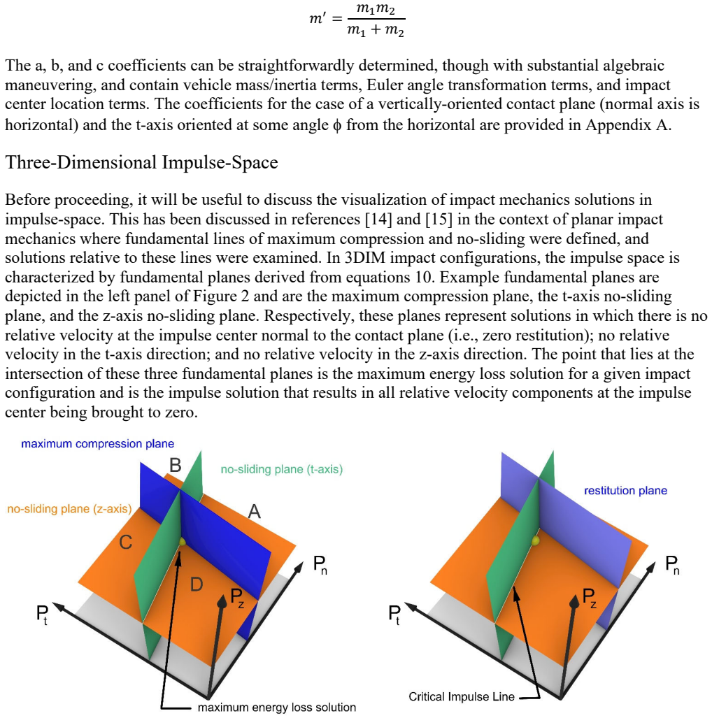
The load-bearing object is the set of equations (9), which express the change in post-impact relative velocity at the impulse center as a linear combination of the three impulse components through coefficients $a_i$, $b_i$, and $c_i$ assembled from the masses, inertia tensors, Euler-angle transformation matrices, and impulse-center position vectors of both vehicles. These coefficients convert the collision problem into a choice of constraints in a three-dimensional impulse space. The paper names the intersection of the t-axis and z-axis no-sliding planes the Critical Impulse Line: any impulse solution on this line leaves no relative sliding velocity in the contact plane after impact, while solutions off the line leave sliding, possibly in a direction rotated from the initial sliding velocity (a swerve). The Appendix A coefficient definitions assume vehicle symmetry about the x-z plane with $I_{xy}=I_{yz}=0$ and neglect $I_{xz}$, an assumption the paper attributes to the commercial implementations.
What would settle it
Instrument a staged 90-degree intersection collision using vehicles whose full inertia tensors are known, measure pre- and post-impact motion, and compare the observed impulse with the predictions of equations (10)-(12) computed both with the diagonal-tensor coefficients of Appendix A and with the full inertia tensor; if the diagonal-assumption prediction differs from measurement by more than the instrumentation error, the derivation's symmetry assumption fails. For the simulator-identification claim, run a 90-degree side impact in Virtual CRASH with a small vertical component added to the bullet vehicle's initial velocity: the PC-Crash-style solution predicts the impulse stays on the Full-Impact solution plane, whereas the alignment strategy of reference [17] prescribes a different relation between the impulse orientation and the initial sliding direction.
Extended reading notes
Core claim
The central claim is that a complete three-dimensional formulation follows from the Newton-Euler equations once three constraint relationships at the impulse center are chosen. Reducing the equations to the three impulse-center relative-velocity components (equation 9) leaves six unknowns; extending the PC-Crash Full-Impact logic sets all three post-impact relative-velocity components to zero at the end of compression and yields the three explicit impulse formulas (equations 10-12). The Sliding-Impact variant confines the solution to a plane in impulse space whose orientation is fixed by the zero-restitution Full-Impact solution and replaces two of the constraints with a single impulse-ratio/friction relation $P_{CP} = \mu_{user} P_n$. In this impulse space the paper defines the maximum-compression plane, the t-axis no-sliding plane, the z-axis no-sliding plane, and the Critical Impulse Line; the Full-Impact solution at zero restitution sits at their common maximum-energy-loss point. The paper further shows that the tangential-alignment strategy of reference [17], which sets the out-of-plane impulse component to zero, generally cannot produce a full-stick solution and necessarily leaves a post-impact sliding component out of the analyst's control. Finally, using a simple 90-degree side impact, the paper demonstrates that Virtual CRASH's output impulses follow the PC-Crash solution-plane geometry rather than the alignment strategy its user guide describes.
Load-bearing premise
Every coefficient formula and impulse solution assumes the two vehicles have diagonal inertia tensors, with the x-y and y-z products of inertia zero and the x-z product negligible; a vehicle with asymmetric crush or loading violates this assumption and falls outside the derivation.
Editorial extensions
If this is right
- Analysts can now compute post-impact velocities for a three-dimensional collision from the explicit impulse formulas (10)-(12) rather than treating the simulation program as a black box.
- A simulator's constraint strategy can be identified by checking whether its output impulses lie on a single solution plane in impulse space, as the paper does for the 90-degree side-impact example.
- In the PC-Crash-style Full-Impact solution, non-zero restitution implies post-impact sliding reversed relative to the initial sliding direction; Sliding-Impact solutions can also reverse sliding, so 'friction' settings act as impulse ratios, not coefficients of friction.
- The alignment-with-initial-sliding strategy cannot reproduce a full-stick impact and will generally leave an out-of-plane sliding component, so swerve is not directly controllable under that model.
- The only formulation discussed that lets the analyst steer both contact-plane sliding components to zero is the two independent impulse-ratio approach, at the cost of specifying an extra empirical parameter.
Reading between the lines
- If the identification of the simulator's actual model is right, the same impulse-vector orientation test could fingerprint other undocumented collision solvers, provided the contact-plane normal and vehicle inertial data are known.
- The existence of the Critical Impulse Line suggests a practical calibration strategy: staged crash tests with measured post-impact residual velocity could be used to infer which impulse ratio (or pair of ratios) places the solution on that line, giving a parameter that is less ambiguous than 'friction'.
- Because the coefficient formulas assume a diagonal inertia tensor, applying the equations to heavily loaded or asymmetrically damaged vehicles requires either full inertia data or an extended derivation; this is a testable boundary of the paper's model.
- The two-parameter impulse-ratio model, though impractical for routine reconstruction, could serve as a way to quantify anisotropic crush behavior if fitted against instrumented crash data.
Editorial analysis
A structured set of objections, weighed in public.
Referee Report
Summary. The paper presents a three-dimensional rigid-body impact mechanics (3DIM) derivation for automobile collision analysis. The author extends the two-dimensional PC-Crash Full-Impact/Sliding-Impact constraint strategies to three dimensions, deriving impulse solutions for the Full-Impact (Eqs. 10–12) and Sliding-Impact (Eqs. 17–18) cases, and discussing Wach's alternative contact-plane strategy and a brief formulation with independent impulse ratios. The paper also introduces an impulse-space visualization with fundamental planes and a Critical Impulse Line, and reports a Virtual CRASH simulation example intended to show that the software's 3D impact model follows the PC-Crash approach rather than the Wach approach described in its User's Guide.
Significance. If correct, the paper fills a documented gap by providing the complete 3DIM derivation for constraint strategies used in commercial accident reconstruction software, and it offers a method to identify which strategy a program actually implements. The derivation is presented with explicit coefficient formulas in Appendix A, which can in principle be checked symbolically, and the impulse-space concepts (e.g., the Critical Impulse Line) provide a useful conceptual framework. The empirical identification of Virtual CRASH's underlying model is an interesting and potentially valuable finding, but it currently rests on a single example and an underived conversion formula, so the strength of the paper's contribution depends on how these are addressed.
major comments (3)
- [Virtual CRASH example, Eq. (29)] Equation (29) is asserted without derivation, yet it is the sole quantitative link between the measured impulse orientation angles (n_i, n_z) and the contact-plane impulse ratio P_z/P_t. This equation is load-bearing for the paper's central empirical claim that Virtual CRASH follows the PC-Crash approach. The paper should derive Eq. (29) from the geometry of the impulse vector and clearly define all symbols it contains, including the angle denoted psi with a subscript (appearing as an OCR artifact in the text), which is never defined.
- [Virtual CRASH example] The conclusion that Virtual CRASH 'in practice ... follows the PC-Crash approach' is based on a single 90-degree side-impact configuration with two friction values. The abstract and conclusion present this as a central result, but a single example cannot establish the software's behavior across the range of impact geometries, restitution values, and friction values it supports. Either additional example configurations should be presented, or the claim should be explicitly limited to the tested configuration.
- [Appendix A and main text] The coefficient definitions in Appendix A assume a diagonal inertia tensor (I_xy = I_yz = 0, with I_xz neglected) and a vertically-oriented contact plane (theta = 0). These restrictions are stated in the appendix, but the main text presents the derivation and the subsequent analysis without emphasizing that all numerical results and the Virtual CRASH identification depend on them. The paper should state these limitations in the main text and discuss the potential impact on the generality of the conclusions, particularly for vehicles with significant products of inertia due to asymmetric damage or loading.
minor comments (4)
- [Eq. (4)] In the second line of Eq. (4), the term involving the angular velocity change for vehicle 2 is written as Delta-omega_2 cross r_1; this appears to be a typo for Delta-omega_2 cross r_2, since the right-hand side of the same equation uses r_2.
- [Figure 8 and surrounding text] The angles n_i and n_z highlighted in Figure 8 are not defined in the text. A sentence explaining the coordinate convention and the measurement of these angles would improve reproducibility of the Virtual CRASH analysis.
- [Transition from Eq. (8) to Eq. (9)] The algebraic expansion from Eq. (8) to Eq. (9) is summarized rather than shown. While the coefficients in Appendix A are explicit, a brief sketch of the expansion or a note that it was verified symbolically would help readers confirm the correctness of the central equations.
- [General presentation] The manuscript contains numerous OCR artifacts and typesetting inconsistencies (e.g., mixed symbols in equations, broken subscripts). A careful proofread is recommended before final submission.
Circularity Check
No significant circularity: the 3DIM derivation is self-contained; the Virtual CRASH identification is an under-validated empirical claim, not a circular one.
full rationale
The central derivation is not circular. Equations (9)-(12) solve the Newton-Euler impulse-momentum equations under the stated Full-Impact constraints (zero post-impact relative velocity at maximum compression with Poisson restitution); the a,b,c coefficients are explicit algebraic functions of mass, inertia, geometry, and Euler angles, and the Cramer's-rule solutions (10)-(12) follow from Eq. (9) by construction. The Sliding-Impact and independent-impulse-ratio branches likewise impose explicit constraints (P_CP=mu P_n, or P_t=mu_t P_n, P_z=mu_z P_n) on the same linear system. Restitution and impulse ratios are user-selected inputs, not fitted parameters, so no fitted-input-called-prediction pattern occurs. Self-citations [14]-[16] supply the impulse-space visualization, the 'Critical Impulse Line' terminology, and a claimed equivalence between the PC-Crash limiting ratio and Ishikawa's GIR; these are interpretive and terminological, not load-bearing, and the underlying formulas are derived in the paper. The only empirical claim—that Virtual CRASH appears to follow PC-Crash rather than Wach—is an observation from one 90-degree side-impact simulation, and Eq. (29) is asserted without derivation; however, that is a robustness/validation concern (single example, unproven angle-to-ratio mapping), not a circular reduction. No equation or result is equivalent to its own inputs by definition. Minor self-citations keep the score at 2 rather than 0.
Assumptions & free parameters
free parameters (3)
- coefficient of restitution (epsilon) =
user-selected (Poisson restitution)
- contact-plane impulse ratio (mu_user) =
user-selected
- independent impulse ratios (mu_t, mu_z) =
user-selected
assumptions (5)
- domain assumption The impulse occurs instantaneously with no translational or rotational displacement of the bodies, and only contact impulses between the vehicles act; impulses from tire/terrain and other compliant sources are excluded.
- standard math Newton's third law applies to the contact impulses, so T1 P1 = -T2 P2.
- domain assumption Vehicle inertia tensors are diagonal: Ixy = Iyz = 0 and Ixz is small enough to neglect.
- domain assumption A coefficient of restitution (Poisson restitution) is an appropriate normal-direction constraint.
- domain assumption For the Appendix A coefficients, the contact plane normal axis is horizontal (theta = 0).
Cite this review
Pith. "Pith review of Three-Dimensional Rigid-Body Impact Mechanics for Automobile Collisions." pith.science (2026). https://pith.science/paper/XYVM2AXN
@misc{pith2026250708033,
  author       = {Pith},
  title        = {Pith review of: Three-Dimensional Rigid-Body Impact Mechanics for Automobile Collisions},
  year         = {2026},
  howpublished = {\url{https://pith.science/paper/XYVM2AXN}},
  note         = {Machine review of arXiv:2507.08033}
}
read the original abstract
Two-dimensional (planar) rigid-body impact mechanics for application in automobile collisions have been described by a number of researchers over the last several decades. Little has been discussed, however, regarding three-dimensional rigid-body impact mechanics in this regard. Two commercially available accident simulation programs, PC-Crash and Virtual CRASH, offer three-dimensional rigid-body impact mechanics as one of their collision models but documentation of the complete development of their three-dimensional equations, particularly with respect to necessary constraint strategies at the impulse center, are not readily available. In this paper, a three-dimensional rigid-body impact mechanics derivation is presented. In order to solve the set of impact mechanics equations of motion it is necessary to develop constraint relationships. The constraint strategy described in the literature pertaining to the PC-Crash Full-Impact/Sliding-Impact scenarios for two dimensions is extended to the three-dimensional case and the ramifications regarding post-impact relative velocity at the impulse center is discussed. A second strategy in which an impulse component is aligned with the contact plane component of the initial relative velocity at the impulse center is presented and compared to the PC-Crash scenarios. Lastly, while these two strategies incorporate a single impulse ratio/friction parameter for the contact plane, a strategy involving two independent impulse ratio/friction parameters is briefly discussed.
Figures


Figures from the paper (5 more)


Reference graph
Works this paper leans on
-
[1]
Vehicle Mechanics of Intersection Collision Impact,
Emori, R., “Vehicle Mechanics of Intersection Collision Impact,” Society of Automotive Engineers, Paper No. 700177, 1970
work page 1970
-
[2]
The ‘IMPAC’ Computer Program for Accident Reconstruction,
Woolley, R., “The ‘IMPAC’ Computer Program for Accident Reconstruction,” Society of Automotive Engineers, Paper No. 850254, 1985
work page 1985
-
[3]
The ‘IMPAC’ Program for Collision Analysis,
Woolley, R., “The ‘IMPAC’ Program for Collision Analysis,” Society of Automotive Engineers, Paper No. 870046, 1987
work page 1987
-
[4]
Linear and Rotational Momentum for Computing Impact Speeds in Two-Car Collisions (LARM),
Limpert, R., and Andrews, D., “Linear and Rotational Momentum for Computing Impact Speeds in Two-Car Collisions (LARM),” Society of Automotive Engineers, Paper No. 910123, 1991
work page 1991
-
[5]
Impact Model for Accident Reconstruction – Normal and Tangential Restitution Coefficients,
Ishikawa, H., “Impact Model for Accident Reconstruction – Normal and Tangential Restitution Coefficients,” Society of Automotive Engineers, Paper No. 930654, 1993
work page 1993
-
[6]
Impact Center and Restitution Coefficients for Accident Reconstruction,
Ishikawa, H., “Impact Center and Restitution Coefficients for Accident Reconstruction,” Society of Automotive Engineers, 940564, 1994
work page 1994
-
[7]
Conservation of Momentum Analysis of Two-Dimensional Colliding Bodies, With or Without Trailers,
Smith, G., “Conservation of Momentum Analysis of Two-Dimensional Colliding Bodies, With or Without Trailers,” Society of Automotive Engineers, Paper No. 940566, 1994
work page 1994
-
[8]
An Impact Moment Coefficient for Vehicle Collision Analysis,
Brach, R., “An Impact Moment Coefficient for Vehicle Collision Analysis,” Society of Automotive Engineers, Paper No. 770014, 1977
work page 1977
Show all 20 references
-
[9]
Friction, Restitution, and Energy Loss in Planar Collisions,
Brach, R., “Friction, Restitution, and Energy Loss in Planar Collisions,” Transactions of the ASME, 164/Vol. 51, 1984
1984
-
[10]
Mechanical Impact Dynamics,
Brach, R., “Mechanical Impact Dynamics,” John Wiley & Sons, New York, NY, 1991
1991
-
[11]
Vehicle Accident Analysis and Reconstruction Methods,
Brach, R., and Brach, R.M., “Vehicle Accident Analysis and Reconstruction Methods,” SAE International, Warrendale, PA, 2005
2005
-
[12]
PC-Crash Operating and Technical Manual, Version 10.0, November 2013
2013
-
[13]
Virtual CRASH: Accident Reconstruction Software User’s Guide, Virtual CRASH, LLC., 2020
2020
-
[14]
The Lost Energy of Planar Impact Mechanics,
Marine, M., “The Lost Energy of Planar Impact Mechanics,” Collision Magazine, Vol. 17, Issue 1, 2023
2023
-
[15]
Restitution, Impulse Space, and Orientations,
Marine, M., “Restitution, Impulse Space, and Orientations,” Collision Magazine, Vol. 16, Issue 1, 2022
2022
-
[16]
On the Concept of Inter-Vehicle Friction and its Application in Automobile Accident Reconstruction,
Marine, M., “On the Concept of Inter-Vehicle Friction and its Application in Automobile Accident Reconstruction,” Society of Automotive Engineers, Paper No. 2007-01-0744, 2007
2007
-
[17]
Spatial Impulse-Momentum Collision Model in Programs for Simulation of Vehicle Accidents,
Wach, W., “Spatial Impulse-Momentum Collision Model in Programs for Simulation of Vehicle Accidents,” XII International Science-Technical Conference, 2020
2020
-
[18]
Impact Mechanics,
Stronge, W., “Impact Mechanics,” Cambridge University Press, Cambridge, UK, 2000
2000
-
[19]
Impact: The Theory and Physical Behavior of Colliding Solids,
Goldsmith, W., “Impact: The Theory and Physical Behavior of Colliding Solids,” Dover Publications, Mineola, NY, 2001
2001
-
[20]
Residual Crush Energy Partitioning, Normal and Tangential Energy Losses,
Brach, R., Welsh, K., and Brach, R.M., “Residual Crush Energy Partitioning, Normal and Tangential Energy Losses,” Society of Automotive Engineers, Paper No. 2007-01-0737, 2007. Appendix A: Coefficient Definitions In an effort achieve some brevity for the resulting coefficient ...
2007
Reviewed August 6, 2026 · model on record in the stance chip above.
Discussion (0). Continue with ORCID to comment.