REVIEW 4 major objections 3 minor 33 references
All-polarisation beamsplitters for interferometer applications
T0 review · 4 major / 3 minor · reviewed 2026-08-06 · deepseek-v4-flash
Pith's one-line read Two industrially fabricated beamsplitter coatings approach the polarisation-symmetric reflection and phase needed for polarisation-based speedmeters in gravitational-wave detectors.
desk verdict A careful, useful coating characterization whose headline numbers are not yet consistent between abstract and body — fix the numbers and release data, and it's a solid contribution. read the letter →
The pith
A machine-rendered reading of the paper's core claim, the machinery that carries it, and where it could break.
The reading
What carries the argument
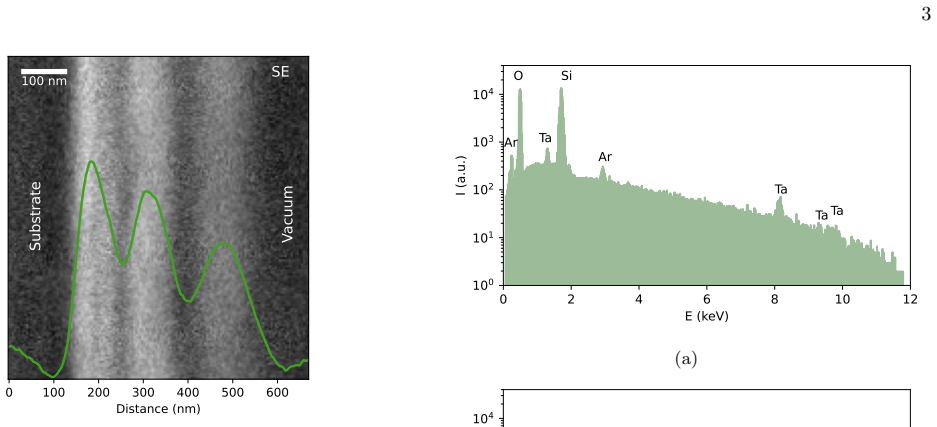
The argument is carried by two multilayer coating stacks and two optical setups. The Laseroptik stack is 22 alternating Ta2O5/SiO2 layers about 5 micrometres thick; the Optoman stack is 5 layers of SiO2 and SiOx about 0.4 to 0.5 micrometres thick. Power splitting is measured from reflected and transmitted powers at 1550 nm over a +-2 degree range around 45 degrees incidence, using R = PR/(PR+PT) to remove sensitivity to power fluctuations. Differential phase is measured in a scanning Michelson interferometer: the p- and s-polarisation outputs form fringe signals, and the phase between them is recovered by Pearson correlation and Lissajous-ellipse fitting. A -1.75 degree offset, measured with single-polarisation light, is subtracted as a common-mode phase from all datasets.
What would settle it
Measure the differential phase of a Laseroptik sample at 44.25 degrees incidence with an independent technique that does not rely on subtracting the common-mode offset, for example spectroscopic ellipsometry or a dual-wavelength interferometer; if the zero-crossing angle moves by more than the roughly 1.5 degree sample-to-sample variation, the common-mode offset assumption is wrong.
Extended reading notes
Core claim
The paper reports the characterisation of two best-effort all-polarisation beamsplitter coatings. A 22-layer Ta2O5/SiO2 coating from Laseroptik achieves equal power reflectivity of 51% for s- and p-polarisation at 46 degrees angle of incidence and zero differential phase shift at 44.25 degrees. A 5-layer SiO2/SiOx coating from Optoman achieves power reflectivities of 49% for s-polarisation and 51% for p-polarisation, with a differential phase shift of about 5 degrees that is largely independent of angle of incidence. Both are measured at 1550 nm and compared with an off-the-shelf s-optimised beamsplitter, and the layer structures are reconstructed with SEM and EDX. The paper concludes that the two design goals for all-polarisation beamsplitters, polarisation-independent power splitting and polarisation-independent phase, are approachable with existing industrial coating technology, although neither coating meets both goals at the target 45-degree angle.
Load-bearing premise
A -1.75 degree phase offset, measured once with only p- or s-polarised light, is assumed to be the same for every sample and every angle and is subtracted from all phase measurements; if it changes with sample or angle, the reported zero-crossing and residual phases shift accordingly.
Editorial extensions
If this is right
- The Laseroptik 22-layer design has enough free parameters that a re-optimisation could bring the equal-reflectivity and zero-phase points together at 45 degrees, provided deposition tolerances are controlled.
- The Optoman design's angle-insensitive phase means that, once the residual roughly 5-degree shift is compensated, the coating could tolerate larger alignment errors than the Laseroptik design.
- Residual differential phase can be handled at the interferometer level by a phase plate or temperature control, or by operating away from 45 degrees and compensating with intermediate telescopes planned for future detectors.
- The characterisation method, power-ratio measurement plus scanning Michelson with Lissajous phase readout, applies directly to other beamsplitter coatings for polarisation-symmetric interferometry.
Reading between the lines
- If the -1.75 degree common-mode offset is not truly constant across samples and angles, the reported zero-crossing angle of 44.25 degrees for Laseroptik and the roughly 5-degree residual for Optoman could shift by more than the stated uncertainties; an independent phase measurement that avoids this subtraction would settle it.
- A natural next step is to use the reconstructed layer thicknesses to simulate both coatings and invert the design problem, asking which thickness changes would put equal reflectivity and zero phase at 45 degrees; the Laseroptik stack's 22 layers make this a plausible optimisation.
- The angle-independent phase of the Optoman coating suggests a single birefringent phase plate placed after the beamsplitter could null the 5-degree shift over the whole angular range, a cheap fix worth testing.
- The paper's approach could also qualify coatings for space-based or optical-communication polarisation-symmetric beamsplitters where angular tolerance matters.
Editorial analysis
A structured set of objections, weighed in public.
Referee Report
Summary. The paper characterizes two commercial beamsplitter coatings, from Laseroptik and Optoman, that were ordered on a best-effort basis to have similar optical properties for s- and p-polarised light, as required for polarisation-based speedmeter interferometers. The authors use SEM/EDX to determine coating structure, a photodiode-based setup to measure power reflectance versus angle of incidence, and a scanning Michelson interferometer with multiple phase-estimation methods to measure the differential phase shift between polarisations. They report that the Laseroptik 22-layer Ta2O5/SiO2 coating achieves equal power reflectivity near 51% and a zero differential phase, while the thinner 5-layer Optoman SiO2/SiOx coating achieves near-50/50 reflectance with a small, angle-insensitive phase shift. The qualitative conclusion is that industrial coatings can approach the all-polarisation beamsplitter specification, but the quantitative claims are currently inconsistent between the abstract and the body.
Significance. If the quantitative claims survive revision, this is a useful and timely experimental contribution: there are few published characterisations of industrially fabricated coatings that approach polarisation-symmetric beam-splitting behaviour, and the connection to polarisation-based speedmeters is relevant for future gravitational-wave detectors. The measurement methodology is a strong point: the paper describes multiple independent phase-estimation methods (Pearson correlation, cross-correlation, Lissajous ellipse fitting), cross-checks statistical uncertainties with Monte Carlo and bootstrap resampling, and uses repeated measurements and sample-to-sample scatter to estimate systematic errors. The SEM/EDX structural analysis is also clearly presented and supports the claimed difference in coating design strategies. However, the paper in its current form does not support the specific headline numbers because the abstract and the body disagree on several of them.
major comments (4)
- [Abstract; Section II B] The central Laseroptik result is internally inconsistent: the abstract states 'equal power reflectivity of 51% at 46 deg angle of incidence', while Section II B states that for the plane beamsplitter samples (LO-P) the equal-reflectance condition is met 'close to 47 deg at 51% reflectance'. The measurement grid in Section II B uses 0.5° steps, so 46° and 47° are not interchangeable without showing the data or the interpolation procedure. No raw data or per-sample tables are provided, so a reader cannot determine which number is correct. Please harmonise the abstract with the body and provide the underlying data or an explicit statement of how the equality angle was obtained.
- [Abstract; Section II B] The Optoman reflectivity values are reversed between abstract and body. The abstract reports '49% for s-polarisation and 51% for p-polarisation', whereas Section II B states that the averaged reflectance is '~51% for s-polarised light and ~49% for p-polarised light'. Since the paper's key claim concerns the magnitude and sign of |Rp - Rs|, this is a material discrepancy that must be corrected before the results can be cited.
- [Abstract; Section III] The reported differential phase values for the two coatings are not consistent within the manuscript. The abstract quotes the Optoman differential phase as 'around 5 deg', while Section III states a 'dark fringe offset of Δφbs ∼ 7°'; given the quoted measurement-to-measurement standard deviation of less than 1.5° (Section II C), these values are not compatible at the stated precision. In addition, the Laseroptik zero-phase crossing at 44.25° appears only in the abstract; the body (Section III) states only that the zero-phase condition is reached 'for a smaller angle of incidence compared to the target 45°'. Please make the reported values consistent and specify which samples and data sets produce each headline number.
- [Section II C] The common-mode phase offset of -1.75°, measured with only p- or s-polarised light, is subtracted from all phase-shift data, but its uncertainty and any possible dependence on sample or angle are not propagated into the reported zero-crossing angle or residual phase values. The text says there were 'no large variations' but gives no quantitative bound. Given that the quoted systematic uncertainty from repeated measurements is already 1.5°, this offset should be treated as a systematic error and propagated before the headline phase results are considered established.
minor comments (3)
- [Section II A] The definition of SiOx is internally inconsistent: the introduction and Section II A define the material as SiOx with 0 < x < 2, but the text later says 'SiO_x is either amorphous silicon (x = 0) or substoichiometric silicon oxide (0 < x < 2)'. Since x = 0 falls outside the earlier range, please reconcile the definition.
- [Fig. 7 caption] The word 'introcuded' in the caption of Fig. 7 should be 'introduced'.
- [Section II B] Equation (1) defines reflectance as R = PR/(PR + PT), which assumes negligible absorption and scattering. A sentence stating whether losses were checked to be negligible would strengthen the interpretation of the reported reflectance values.
Circularity Check
No circularity: the paper's central claims are direct external measurements, not derivations from their own inputs.
full rationale
The load-bearing claims — power reflectivity vs angle of incidence and differential phase shift vs angle for the Laseroptik and Optoman coatings — are obtained from two independent optical setups (Figs. 5 and 7) using standard calibrated photodiodes, fringe analysis, Pearson correlation, cross-correlation, and Lissajous ellipse fitting. The only data-derived correction applied to the phase results is the measured −1.75° common-mode offset, which was obtained separately with only p- or s-polarised light and then subtracted uniformly; it is not a fitted parameter chosen to force a desired outcome. No coating parameter is fitted to a subset of the reported data and then presented as a prediction. Self-citations (e.g., refs. [6,13]) appear only as background motivation for why polarisation-symmetric beamsplitters are relevant to speedmeters; they do not provide the measured coating performance or the analysis methods. The manuscript's internal inconsistency between abstract values (46°, 49%/51%, ~5°) and body values (47°, ~51%/~49%, ~7°) is a correctness and reproducibility concern, not a circularity. Accordingly, no circular step can be exhibited, and the circularity score is 0.
Assumptions & free parameters
free parameters (3)
- Photodiode calibration factors (V/W) =
not stated in paper
- Common-mode phase offset =
-1.75 deg
- Piezo length coupling cpz =
calibrated to lambda = 1550 nm
assumptions (4)
- standard math Fresnel equations govern polarisation-dependent reflectance and phase at dielectric interfaces.
- domain assumption EDX and BSE contrast identify the coating materials as Ta2O5/SiO2 for Laseroptik and SiOx/SiO2 for Optoman.
- domain assumption The fringe signals are single-frequency cos^2 fringes away from piezo ramp turning points.
- domain assumption The measured -1.75 deg phase offset is common-mode and independent of sample and angle.
Cite this review
Pith. "Pith review of All-polarisation beamsplitters for interferometer applications." pith.science (2026). https://pith.science/paper/YS4P42PO
@misc{pith2026250722866,
  author       = {Pith},
  title        = {Pith review of: All-polarisation beamsplitters for interferometer applications},
  year         = {2026},
  howpublished = {\url{https://pith.science/paper/YS4P42PO}},
  note         = {Machine review of arXiv:2507.22866}
}
read the original abstract
Optical beamsplitters with similar properties for orthogonal, linear polarisation modes are required for realising polarisation-based speedmeter schemes to reduce back-action noise in gravitational-wave interferometers. In this paper, we investigate two beamsplitter coatings obtained from Laseroptik GmbH and Optoman on a best-effort basis that aim for a 50/50 power splitting ratio and equal overall phase shift for two orthogonal, linear polarisation modes interacting with the optic. We show that while Laseroptik GmbH opted for coating stack with 22 alternating layers of Ta2O5 and SiO2, Optoman produced a much thinner coating made of 5 SiO2 and SiOx (0 < x < 2) layers. With these strategies, the Laseroptik coating achieves an equal power reflectivity of 51% at 46 deg angle of incidence, and zero phase shift between both polarisations at 44.25 deg angle of incidence. The Optoman coating achieves power reflectivities of 49% for s-polarisation and 51% for p-polarisation with a differential phase shift around 5 deg largely independent of the angle of incidence.
Figures


Figures from the paper (7 more)


Reference graph
Works this paper leans on
-
[1]
J. Aasi, B. Abbott, R. Abbott, T. Abbott, M. Abernathy, K. Ackley, C. Adams, T. Adams, P. Addesso, R. Ad- hikari, et al., Classical and Quantum Gravity 32, 074001 (2015)
work page 2015
-
[2]
F. Acernese et al. (Virgo Scientific Collaboration), Clas- sical and Quantum Gravity 32, 024001 (2015)
work page 2015
- [3]
-
[4]
R. Abbott et al. (LIGO and Virgo Scientific Collabora- tions), Physical Review D 109, 022001 (2024)
work page 2024
-
[5]
Abbott et al., Physical Review X 13, 041039 (2023)
R. Abbott et al., Physical Review X 13, 041039 (2023)
work page 2023
-
[6]
S. Danilishin, F. Khalili, and H. Miao, Living Reviews in Relativity 22 (2019)
work page 2019
- [7]
-
[8]
V. Braginsky, M. Gorodetsky, F. Khalili, and K. Thorne, Physical Review D 61, 044002 (2000)
work page 2000
Show all 33 references
-
[9]
Purdue and Y
P. Purdue and Y. Chen, Physical Review D 66, 122004 (2002)
2002
-
[10]
Chen, Physical Review D 67, 122004 (2003)
Y. Chen, Physical Review D 67, 122004 (2003)
2003
-
[11]
A. Wade, K. McKenzie, Y. Chen, D. Shaddock, J. Chow, and D. McClelland, Physical Review D 86, 062001 (2012)
2012
-
[12]
M. Wang, C. Bond, D. Brown, F. Br¨ uckner, L. Carbone, R. Palmer, and A. Freise, Physical Review D 87, 096008 (2013)
2013
-
[13]
Knyazev, S
E. Knyazev, S. Danilishin, S. Hild, and F. Khalili, Physics Letters A 382, 2219 (2018)
2018
-
[14]
Zukic, K
M. Zukic, K. Guenther, and R. Chipman, in Polarization Considerations for Optical Systems(1988), vol. 891, pp. 238–241
1988
-
[15]
Mordechai, Applied Optics 31, 5345 (1992)
G. Mordechai, Applied Optics 31, 5345 (1992)
1992
-
[16]
J. Feng, C. Zou, J. Zheng, H. Cao, and P. Lv, Applied Optics 48, 5636 (2009)
2009
-
[17]
Shen and D
Z. Shen and D. Huang, Nanomanufacturing 2, 194 (2022)
2022
-
[18]
R. M. A. Azzam and A. De, Journal of the Optical So- ciety of America A 20, 955 (2003), URL https://doi. org/10.1364/JOSAA.20.000955
2003 doi
-
[19]
Zhang and A
K. Zhang and A. Smajkiewicz, in Proc. SPIE 6105, Free- Space Laser Communication Technologies XVIII(2006), vol. 6105, p. 61050I, published 1 March 2006, URL https://doi.org/10.1117/12.644885
2006 doi
-
[20]
Rothhardt, P
C. Rothhardt, P. Birckigt, K. Grabowski, S. Risse, R. Schlegel, S. Shestaeva, S. Schwinde, S. Schmidl, and S. Klose, in Proc. SPIE 12777, International Conference on Space Optics — ICSO 2022 (2023), vol. 12777, p. 1277719, presented at the International Conference on Space Opt...
2023 doi
-
[21]
J. I. Goldstein, D. E. Newbury, J. R. Michael, N. W. Ritchie, J. H. J. Scott, and D. C. Joy, Scanning electron microscopy and X-ray microanalysis(springer, 2017)
2017
-
[22]
Q. Song, F. Huang, M. Li, B. Xie, H. Wang, Y. Jiang, and Y. Song, Journal of Vacuum Science & Technology A 26, 265 (2008), URL https://doi.org/10.1116/1.2837836
2008 doi
-
[23]
J. L. Rodgers and W. A. Nicewander, The American Statistician 42, 59 (1988), ISSN 00031305, URL http: //www.jstor.org/stable/2685263
1988
-
[24]
Halir and J
R. Halir and J. Flusser, In Proc. 6th International Con- ference in Central Europe on Computer Graphics and Visualization 98, 125 (1998)
1998
-
[25]
L.-W. Wei, H. Hollis, B. Willke, A. D. Spector, and G. Mueller, Applied Optics 63, 3406 (2024), URL https: //doi.org/10.1364/AO.519987
2024 doi
-
[26]
L.-W. Wei, J. H. Pold, D. Schmelzer, K. Karan, and B. Willke, Applied Optics 63, 3445 (2024), URL https: //doi.org/10.1364/AO.519988
2024 doi
-
[27]
Rowlinson, A
S. Rowlinson, A. Dmitriev, A. W. Jones, T. Zhang, and A. Freise, Phys. Rev. D 103, 023004 (2021), URL https: //link.aps.org/doi/10.1103/PhysRevD.103.023004
2021 doi
-
[28]
Srivastava, D
V. Srivastava, D. Davis, K. Kuns, P. Landry, S. Ballmer, M. Evans, E. D. Hall, J. Read, and B. S. Sathyaprakash, The Astrophysical Journal 931, 22 (2022), URL https: //dx.doi.org/10.3847/1538-4357/ac5f04
2022 doi
-
[29]
Reitze, R
D. Reitze, R. X. Adhikari, S. Ballmer, B. Barish, L. Bar- sotti, G. Billingsley, D. A. Brown, Y. Chen, D. Coyne, R. Eisenstein, et al., Cosmic explorer: The u.s. contribu- tion to gravitational-wave astronomy beyond ligo(2019), 1907.04833, URL https://arxiv.org/abs/1907.04833
2019 arXiv
-
[30]
Evans, R
M. Evans, R. X. Adhikari, C. Afle, S. W. Ballmer, S. Bis- coveanu, S. Borhanian, D. A. Brown, Y. Chen, R. Eisen- stein, A. Gruson, et al., A horizon study for cosmic ex- plorer: Science, observatories, and community (2021), 2109.09882, URL https://arxiv.org/abs/2109.09882
2021 arXiv
-
[31]
Punturo et al., Classical and Quantum Gravity 27, 194002 (2010), URL https://doi.org/10.1088/ 0264-9381/27/19/194002
M. Punturo et al., Classical and Quantum Gravity 27, 194002 (2010), URL https://doi.org/10.1088/ 0264-9381/27/19/194002
2010
-
[32]
Maggiore et al., Journal of Cosmology and Astroparti- cle Physics 2020, 050–050 (2020), ISSN 1475-7516, URL http://dx.doi.org/10.1088/1475-7516/2020/03/050
M. Maggiore et al., Journal of Cosmology and Astroparti- cle Physics 2020, 050–050 (2020), ISSN 1475-7516, URL http://dx.doi.org/10.1088/1475-7516/2020/03/050
2020 doi
-
[33]
Abac et al., The science of the einstein tele- scope (2025), 2503.12263, URL https://arxiv.org/ abs/2503.12263
A. Abac et al., The science of the einstein tele- scope (2025), 2503.12263, URL https://arxiv.org/ abs/2503.12263
2025 arXiv
Reviewed August 6, 2026 · model on record in the stance chip above.
Discussion (0). Sign in to comment.