REVIEW 4 major objections 5 minor 2 cited by
Detailed Design and Optimization of Ferro-Electric Tuners
T0 review · 4 major / 5 minor · reviewed 2026-08-16 · deepseek-v4-flash
Pith's one-line read Closed-form design equations for ferroelectric fast reactive tuners predict full-wave results well enough to provide starting parameters.
desk verdict A genuinely useful engineering-design methodology for ferroelectric reactive tuners, but the 'excellent agreement' with CST is overstated: the analytic model overpredicts tuning range by 13–20%, and the 400 MHz case only hits target by post-hoc adjusting Qe. read the letter →
The pith
A machine-rendered reading of the paper's core claim, the machinery that carries it, and where it could break.
The reading
What carries the argument
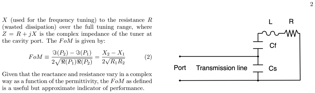
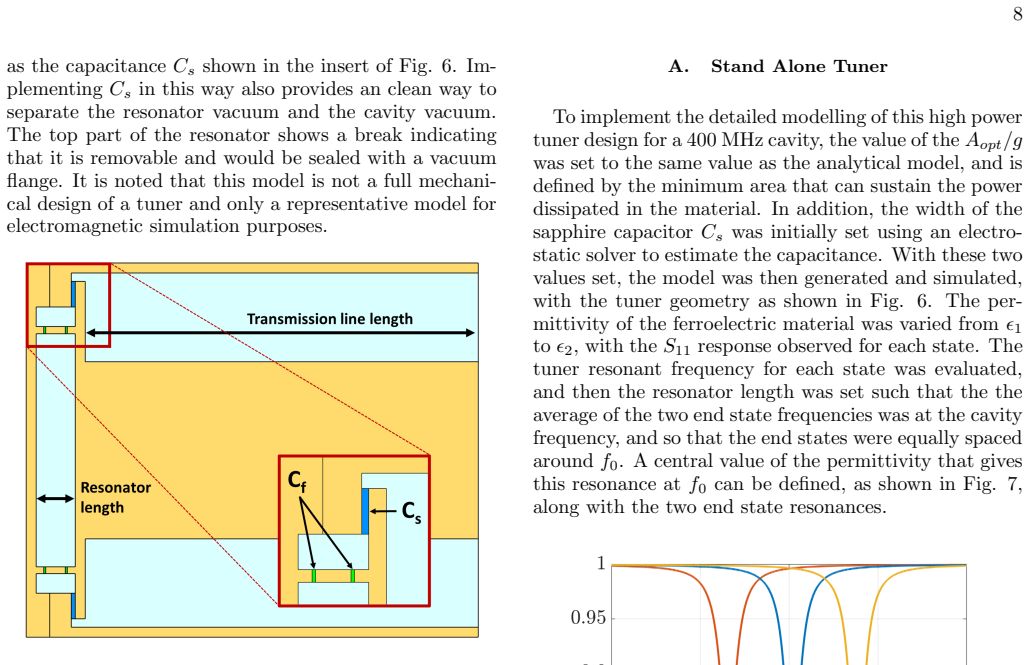
The load-bearing object is the equivalent circuit of a ferroelectric capacitor $C_f$ in a series LCR resonator, a coupling capacitor $C_s$, and a quarter-wave transmission line of characteristic impedance $Z_0$ to the cavity. The resonator's inductance is modeled as a short coaxial line, so its resistive loss is expressed through the transmission-line attenuation $\alpha$ and end-wall resistance $R_B$. The identity that carries the argument is the transformed tuner impedance $Z_L = Z_0^2/Z_r$, which turns the resonator's reactance change into a tuning range through $\Delta \omega_{12} = (\omega_0/(2Q_e)) (X_2-X_1)/Z_0$, and the Figure of Merit $\mathrm{FoM} = (X_2-X_1)/(2\sqrt{R_1R_2})$, which reduces to $C_s/[(C_s+C_f)Q] \cdot \Delta\epsilon/(2\epsilon_c)$. These equations let the designer set $Q_e$, $C_s$, $l_r$, and the conductor radii in closed form before any 3D simulation.
What would settle it
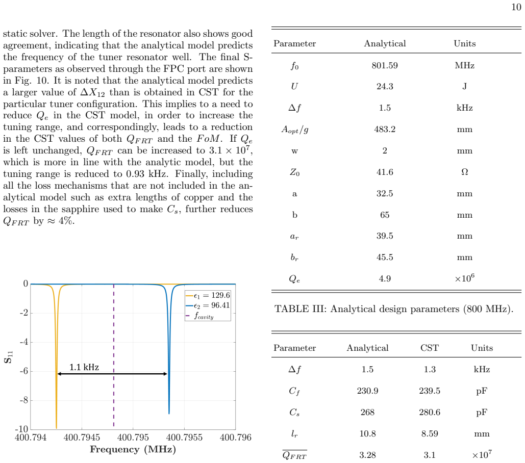
Take the paper's 400 MHz, 1.9 MVAR parameters and simulate the tuner attached to the cavity with the line length and $Q_e$ fixed at their analytic values; if the end-state frequency splitting differs from 1.1 kHz by more than about 15%, or if the two end-state resonances are not centered within 0.01 kHz of $f_0$, the claim that the analytic model provides accurate starting parameters fails.
Extended reading notes
Core claim
The central claim is that the FE-FRT can be reduced to a capacitively coupled series-LCR resonator transformed by a quarter-wave transmission line, and that every design quantity follows from three inputs: $f_0$, $U$, and $\Delta f$. The paper derives closed expressions for the ferroelectric stack capacitance $C_f$, the coupling capacitor $C_s$, the resonator length $l_r$, the tuner quality factor $Q$, the external quality factor $Q_e$, and the Figure of Merit $\mathrm{FoM}$, and it optimizes conductor radii through a simultaneous optimization of the ratio $b_r/a_r$ and the parameter $D=(X_2-X_1)/(2Z_0)$. The claim is verified by comparing analytic values with finite-element simulation of two concrete tuners; the simulation reproduces the tuned-frequency splitting to within about 15% before compensation, and the capacitance values to within a few percent, with the remaining FoM difference attributed to loss mechanisms the analytic circuit omits.
Load-bearing premise
The entire design procedure rests on the equivalent circuit of a ferroelectric capacitor in a series LCR resonator with a coupling capacitor and a quarter-wave line; if parasitic resonances, wafer-field nonuniformity, or transmission-line losses break that circuit representation, the closed-form design equations lose their predictive accuracy.
Editorial extensions
If this is right
- A cavity designer can go from frequency, stored energy, and tuning range straight to component values, so feasibility studies that previously needed a full-wave design cycle can be done with a short script.
- The optimized Figure-of-Merit curves give a quick bound on achievable performance; for the paper's examples, the FoM is near 100 at 100 kVAR and above 200 at low frequency for 1 MVAR, letting a user judge a tuning scenario at a glance.
- Two-wafer ferroelectric stacks are sufficient for most designs; more wafers do not improve the FoM at low reactive power and add mechanical complication, so the paper recommends two-wafer designs as the default.
- In the full-wave checks, the quarter-wave line length is set by minimizing the tuning range and $Q_e$ may need a small adjustment to recover the full range, so the analytic values are a starting point rather than a final answer.
Reading between the lines
- If the same circuit topology holds at higher frequencies, the closed-form procedure could be extended to normal-conducting cavities and to frequency-agile filters by replacing stored energy with bandwidth as an input.
- Because the equations separate dielectric loss from conductor loss, a testable consequence is that the Figure of Merit should scale inversely with loss tangent only at low frequency; at high frequency, conductor loss should cap the FoM and flatten the curves.
- The validation covers only two designs; extending the comparison to the stated low-frequency truncation boundary, where the resonator length approaches $\lambda/8$ and the coaxial-line approximation of the inductor becomes questionable, would define the model's actual range of validity.
Signed reviews
Editorial analysis
A structured set of objections, weighed in public.
Referee Report
Summary. The paper presents a step-by-step analytic design methodology for a ferroelectric fast reactive tuner (FE-FRT). Given the cavity frequency, stored energy, and required tuning range, it gives closed-form expressions for the ferroelectric capacitance, series coupling capacitance, resonator length, external quality factor, and a figure of merit (FoM) for tuner performance. The design is based on an equivalent circuit of a ferroelectric capacitor in a resonant LCR circuit with a quarter-wave transmission line to the cavity, and the paper includes optimization procedures for the wafer geometry, conductor radii, and coupling. The analytic results are compared with CST Studio Suite electromagnetic simulations for a 400 MHz 1.9 MVAR tuner and an 800 MHz 458 kVAR tuner. The authors claim that the analytic expressions closely approximate the CST results and provide an accurate set of initial design parameters.
Significance. If the methodology were quantitatively validated, it would be a useful engineering contribution: it reduces early-stage FE-FRT design to closed-form equations, relates material-level figures of merit to tuner-level performance, and provides design curves over frequency and reactive power. The paper is transparent in giving the full simulation procedure and comparison tables. A positive feature is the consistency check that the tuner FoM of Eq. (16) reduces to the bare ferroelectric FoM of Eq. (4) when conductor losses are neglected. However, the validation shows systematic discrepancies of 13-20% that are not reflected in the 'excellent agreement' claim. Because the central claim concerns quantitative predictive accuracy, these discrepancies are load-bearing and need to be addressed in revision.
major comments (4)
- [V.C, Table IV] The 800 MHz case is the only clean test of the analytic predictions because Qe was not adjusted. The analytic model overpredicts the tuning range by 13% (1.5 kHz vs. 1.3 kHz), the FoM by 13% (56.6 vs. 49.3), and the resonator length by 20% (10.8 mm vs. 8.59 mm). These are systematic deviations of the same order as the 400 MHz case once the Qe adjustment is accounted for. The statement in Section V.C that 'the agreement ... is excellent' is therefore not supported by the data. The authors should quantify these deviations, identify their likely sources, and either correct the model or revise the claim to 'agreement at the 10-20% level' with explicit error margins.
- [V.B, Table II] The 400 MHz validation is not a genuine prediction because Qe was adjusted from 3.25e6 to 2.95e6 to recover the required 1.1 kHz tuning range; with the raw analytic parameters, the tuning range was only 0.97 kHz, a 12% shortfall. Since QFRT and FoM depend directly on Qe, the reported FoM comparison (81.6 analytic vs. 65.3 CST, 20% lower) incorporates a free parameter and cannot be cited as evidence for excellent agreement. The paper should report the unadjusted comparison explicitly and discuss what it implies for the accuracy of the reactance-swing prediction in Eq. (18).
- [Eq. (18), V.B, V.C] The central tuning-range formula, Eq. (18), systematically overpredicts delta-f in both validations: 12% low in the 400 MHz case before Qe adjustment, and 13% low in the 800 MHz case. Because Eq. (18) is the basis for setting Qe and Cs in the design procedure, this overprediction affects the main quantitative deliverable of the paper. The authors should either add a correction term or provide an explicit accuracy bound on Eq. (18) so that a designer can account for the expected margin when using these closed-form expressions.
- [IV and VI] The paper claims in the introduction and summary that a main conclusion is the design advantage of tuners with just two ferroelectric wafer elements, but Section IV itself states that a 4-wafer design 'may have a small performance advantage at low frequencies' at low reactive power. The conclusion about the two-wafer advantage should be qualified to avoid overgeneralization, or the supporting data should be shown more clearly.
minor comments (5)
- [Abstract] The abstract contains a typo: 'operating frequency a cavity stored energy' should be 'operating frequency and cavity stored energy.'
- [II.C] The phrase 'the later is relevant' should be 'the latter is relevant.'
- [III.A] The section heading 'The Modeling the Resonator' should be corrected to 'Modelling the Resonator' or 'Modeling the Resonator.'
- [V.B] The sentence 'the tuning range minima was only 0.97 kHz' should be 'the tuning range minimum was only 0.97 kHz.'
- [V.C] The statement that 'including all the loss mechanisms ... further reduces QFRT by approx 4%' is vague; the authors should specify which loss mechanisms are added and how the 4% estimate was obtained.
Circularity Check
No significant circularity; the analytic derivations are independent of the CST benchmark and the material data.
full rationale
The central design equations (Eqs. 16 and 18) are derived algebraically from the equivalent-circuit definitions in Eqs. (7)-(15) and from externally specified material parameters [5]; they are not fitted to the CST results. The CST comparison is an external full-wave benchmark, and the paper's disclosure that Qe had to be reduced from 3.25e6 to 2.95e6 in the 400 MHz case is a validation caveat, not a circular step: the analytic model is not being tuned to reproduce the simulated FoM. The reduction of Eq. (16) to the pure-ferroelectric FoM of Eq. (4) when conductor losses vanish is explicitly presented as a cross-check, not as an input. The self-citations [1,2] supply the equivalent-circuit topology and Eq. (3), but these are not uniqueness claims and their consequences are independently tested against CST. The 800 MHz case, in which Qe was not adjusted, shows 13-15% deviations that weaken the 'excellent agreement' claim, but disagreement is a correctness risk, not circularity.
Assumptions & free parameters
free parameters (5)
- Annulus width w =
1 mm (low power), 3 mm (high power)
- Allowable temperature rise ΔT =
30 °C
- Spacer thickness =
5 mm for Nw=2, 10 mm for Nw>2
- H limit =
H < 3
- External quality factor Qe (CST validation) =
reduced from 3.25e6 to 2.95e6 at 400 MHz
assumptions (5)
- domain assumption The tuner can be modeled as a lumped-element LCR resonator with ferroelectric capacitor Cf, series capacitor Cs, and short coaxial-line inductor.
- domain assumption The ferroelectric material parameters (permittivity range, loss tangent δ, thermal conductivity K) from supplier data [5] are accurate for the operating conditions.
- domain assumption Approximations in Eq. (13): large quality factor Q, compact resonator so lr << wavelength, and negligible losses in the quarter-wave transmission line.
- domain assumption Heat is extracted uniformly from both faces of each wafer, giving the 1/12 factor in Eq. (5).
- standard math The detuning relation Eq. (15) follows from differentiating Ω^2 = 1/LC.
Cite this review
Pith. "Pith review of Detailed Design and Optimization of Ferro-Electric Tuners." pith.science (2026). https://pith.science/paper/QRD6RRHY
@misc{pith2026250419825,
  author       = {Pith},
  title        = {Pith review of: Detailed Design and Optimization of Ferro-Electric Tuners},
  year         = {2026},
  howpublished = {\url{https://pith.science/paper/QRD6RRHY}},
  note         = {Machine review of arXiv:2504.19825}
}
read the original abstract
A detailed, step-by-step design methodology of a Ferroelectric Fast Reactive Tuner (FE-FRT) capable of modulating Mega VAR reactive powers on a sub-microsecond time scale is given. Closed expressions of values for all the components of the tuner are detailed, and tuner performance optimization is addressed, resulting in a Figure of Merit measure of FE-FRT tuner performance and use case applicability over a wide range of RF frequencies and reactive power levels. This enables addressing feasibility and rapid assessment of design parameters given an FE-FRT tuning scenario defined by required tuning range, cavity operating frequency a cavity stored energy.
Figures


Figures from the paper (7 more)




Forward citations
Cited by 2 Pith papers
-
Design Study of an Endless RF Phase Shifter Using Ferroelectric Capacitors
A ferroelectric-capacitor design winds RF phase endlessly—360° per bounded control cycle—by looping around a reflection-coefficient vortex, with 0.19 dB simulated loss at 400 MHz.
-
Design of a Fast Reactive Tuner for 1.3 GHz TESLA cavities at MESA
A ferroelectric fast reactive tuner design for 1.3 GHz TESLA cavities is presented, with CST simulation showing a 50 Hz tuning range and roughly 12x lower forward RF power.
Reference graph
Works this paper leans on
-
[1]
I. Ben-Zvi, G. Burt, A. Castilla, A. Macpherson, and N. Shipman, Conceptual design of a high reactive-power ferroelectric fast reactive tuner, Physical Review Acceler- ators and Beams 27, 052001 (2024)
work page 2024
-
[2]
High-Power Ferro-Electric Fast Reactive Tuner
I. Ben-Zvi, A. Castilla, A. Macpherson, and N. Ship- man, High-power ferro-electric fast reactive tuner, arXiv preprint arXiv:2109.06806 (2021)
work page Pith review arXiv 2021
-
[3]
Maplesoft: Maple is a trademark of Waterloo Maple Inc., Maple (2024), https://www.maplesoft.com
work page 2024
-
[4]
Dassault Syst` emes, CST Studio Suite, R2024x (2024), https://www.3ds.com/products- services/simulia/products/cst-studio-suite/
work page 2024
-
[5]
A. Kanareykin, E. Nenasheva, S. Karmanenko, A. Dedyk, and V. Yakovlev, Low-loss ferroelectric for accelerator ap- plications, in Proceedings of the 2005 Particle Accelerator Conference (IEEE, 2005) pp. 4305–4307
work page 2005
-
[6]
F. collaboration et al., Fcc-ee: The lepton collider: Future circular collider conceptual design report volume 2, Euro- pean Physical Journal Special Topics 228, 261 (2019)
work page 2019
Reviewed August 16, 2026 · model on record in the stance chip above.
Discussion (0). Continue with ORCID to comment.