PEACC -- Precision Emitter for 21 cm Array Coherent Calibration
Pith reviewed 2026-05-10 15:34 UTC · model grok-4.3
The pith
A drone-mounted noise emitter synchronized only by GPS clocks provides the first free-space coherent calibration for 21 cm radio arrays.
A machine-rendered reading of the paper's core claim, the machinery that carries it, and where it could break.
Core claim
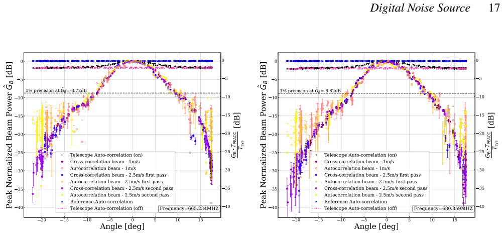
PEACC generates Gaussian noise over a 1.2 GHz bandwidth and is locked to the 1 PPS output of a GPS-disciplined oscillator. A dual-source layout places one emitter on a drone while the second remains connected to the data-acquisition system, enabling direct phase extraction and higher sensitivity at low SNR. Chamber and drone-over-dish measurements showed the correlated channel outperforming auto-correlation in all regimes of interest, establishing the first published free-space coherent calibration signal synchronized solely by clocks and the first such beam measurements obtained from a drone platform.
What carries the argument
Dual-source architecture with one aerial emitter and one reference unit tied to the receiver, both locked to GPS 1 PPS timing, which supplies the common phase reference for coherent cross-correlation without physical cabling.
Load-bearing premise
GPS clock synchronization and free-space propagation introduce no timing or phase errors large enough to destroy the coherence needed for the cross-correlation advantage.
What would settle it
A flight test in which the cross-correlated signal-to-noise ratio fails to exceed the auto-correlated ratio by a statistically significant margin across the target bandwidth and distance range.
Figures


read the original abstract
Foreground mitigation remains a central challenge for 21 cm intensity mapping experiments, which require precise, wideband calibration of telescope beams and gains. We present the Precision Emitter for 21 cm Array Coherent Calibration (PEACC), a digitally synthesized calibration source that generates Gaussian noise across a 1.2 GHz bandwidth, time-synchronized to a 1 pulse-per-second output from a GPS-disciplined oscillator, and optimized for aerial deployment. PEACC uses a dual-source architecture with one unit mounted on an aerial platform and a second reference unit connected directly to the radio data acquisition system; this configuration enables improved sensitivity in the low-SNR regime and direct phase measurement. The system further supports configurable band selection, allowing adaptation to various 21 cm intensity mapping telescopes. We validated PEACC through anechoic chamber measurements and by integrating the source on a drone flown over a local radio dish testbed. In both settings, the correlated channel substantially outperformed the auto-correlation channel across all signal-to-noise regimes of interest, confirming the key advantage of the dual-source architecture. To our knowledge, this is the first published demonstration of a free-space coherent calibration signal synchronized only by clocks, the first deployment of such a source on a drone, and the first published beam measurements made with such a source. Given the growing interest in drone-based calibration for 21 cm arrays, this work establishes the feasibility of high-fidelity digital calibration for next-generation 21 cm instruments, and provides a practical path towards improved foreground control and beam calibration in future arrays.
Editorial analysis
A structured set of objections, weighed in public.
Referee Report
Summary. The paper presents PEACC, a digitally synthesized Gaussian noise source spanning 1.2 GHz bandwidth, time-synchronized via GPS-disciplined 1PPS outputs. It employs a dual-source architecture (one unit on a drone, one reference unit tied to the data acquisition system) to enable direct phase measurements and improved sensitivity in the low-SNR regime for 21 cm array beam and gain calibration. Validation consists of anechoic chamber measurements and drone flights over a local dish testbed, with the correlated channel reported to substantially outperform auto-correlation. The authors position this as the first published free-space coherent calibration signal synchronized only by clocks, first drone deployment of such a source, and first beam measurements obtained with it.
Significance. If the quantitative results hold, this establishes a practical, clock-synchronized aerial calibration technique that could address foreground mitigation challenges in 21 cm intensity mapping by providing direct phase information without relying on astronomical sources. The dual-source approach for low-SNR phase extraction and the successful drone integration represent a concrete advance for next-generation arrays, with the hardware demonstration providing a reproducible path for similar instruments.
major comments (2)
- [Validation results] Validation section (and abstract): the claim that the correlated channel 'substantially outperformed' the auto-correlation channel across SNR regimes is central to the dual-source advantage, yet the manuscript provides no quantitative metrics, error bars, phase RMS values, coherence times, or specific improvement factors from the anechoic or drone tests. Without these, the assertion that timing/propagation errors do not degrade coherence cannot be evaluated.
- [System description and validation] Clock synchronization and dual-source architecture: the system relies on GPS 1PPS locking with free-running oscillators between pulses. At 1.2 GHz a ~1 ns rms timing error produces ~4.3 rad phase error, which would destroy coherence. The paper does not report measured short-term stability (Allan deviation), residual phase jitter across the band, or post-processing propagation delay subtraction accuracy from the drone flights, leaving the 'without significant timing or propagation errors' claim unquantified.
minor comments (2)
- [Introduction] The abstract and introduction would benefit from a brief comparison table or sentence contrasting PEACC with prior drone or ground-based calibration sources to clarify the novelty beyond the 'first published' statements.
- [Figures] Figure captions for the drone flight and anechoic chamber setups should explicitly note the frequency band used, drone altitude, and any post-processing steps applied to the correlated data.
Simulated Author's Rebuttal
We thank the referee for their constructive and detailed review. The comments highlight important areas where additional quantitative detail will strengthen the manuscript. We address each major comment below and will incorporate the suggested clarifications and data in a revised version.
read point-by-point responses
-
Referee: [Validation results] Validation section (and abstract): the claim that the correlated channel 'substantially outperformed' the auto-correlation channel across SNR regimes is central to the dual-source advantage, yet the manuscript provides no quantitative metrics, error bars, phase RMS values, coherence times, or specific improvement factors from the anechoic or drone tests. Without these, the assertion that timing/propagation errors do not degrade coherence cannot be evaluated.
Authors: We agree that the performance comparison requires explicit quantitative support. In the revised manuscript we will add tables and figures reporting the measured improvement factors between correlated and auto-correlation channels, phase RMS values, error bars, and coherence times extracted from both the anechoic-chamber data and the drone-flight datasets. These additions will directly quantify the dual-source advantage and allow independent assessment of residual timing and propagation effects. revision: yes
-
Referee: [System description and validation] Clock synchronization and dual-source architecture: the system relies on GPS 1PPS locking with free-running oscillators between pulses. At 1.2 GHz a ~1 ns rms timing error produces ~4.3 rad phase error, which would destroy coherence. The paper does not report measured short-term stability (Allan deviation), residual phase jitter across the band, or post-processing propagation delay subtraction accuracy from the drone flights, leaving the 'without significant timing or propagation errors' claim unquantified.
Authors: The referee is correct that short-term stability metrics are not currently reported. We will revise the manuscript to include measured Allan deviation of the free-running oscillators on the relevant (sub-second to minute) timescales, estimates of residual phase jitter across the 1.2 GHz band, and the accuracy achieved by post-processing propagation-delay subtraction in the drone data. These quantities will be derived from the existing test datasets and will demonstrate that the effective timing errors remain well below the level that would destroy coherence. revision: yes
Circularity Check
No circularity: hardware instrument paper with direct empirical validation
full rationale
The paper presents the design and field testing of a physical calibration source. No derivations, fitted models, predictions, or ansatzes appear in the provided text. Claims rest on chamber measurements and drone flights comparing correlated vs. auto-correlation channels, with no self-referential equations or load-bearing self-citations. The dual-source advantage is shown by direct performance comparison rather than by construction from inputs.
Axiom & Free-Parameter Ledger
Forward citations
Cited by 1 Pith paper
-
Mapping Cosmological Signal Scales to Beam Calibration Requirements in 21cm Experiments and Implications for Near-Field Measurement
New method maps 21cm cosmological structures to ~100m reflection scales for HERA-like and EDGES-like instruments, showing near-field beam calibration is required.
Reference graph
Works this paper leans on
-
[1]
E., Alexander P., et al., 2022, ApJ, 925, 221
Abdurashidova Z., Aguirre J. E., Alexander P., et al., 2022, ApJ, 925, 221
work page 2022
-
[2]
Amiri M., et al., 2024, @doi [ ] 10.3847/1538-4357/ad8133 , https://ui.adsabs.harvard.edu/abs/2024ApJ...976..163A 976, 163
-
[3]
Bandura K., Addison G. E., Amiri M., et al., 2014, Society of Photo-Optical Instrumentation Engineers (SPIE) Conference Series, 9145, 22
work page 2014
-
[4]
Bandura K., et al., 2016, @doi [Journal of Astronomical Instrumentation] 10.1142/S2251171716410051 , 05, 1641005
-
[5]
Bhopi K., Tyndall W., Sanghavi P., Bandura K., Newburgh L., Gallicchio J., 2022, @doi [Journal of Astronomical Instrumentation] 10.1142/s2251171722500167 , 12
-
[6]
Chang C., Monstein C., Refregier A., Amara A., Glauser A., Casura S., 2015, PASP, 127, 1131
work page 2015
-
[7]
Crichton D., et al., 2022, Journal of Astronomical Telescopes, Instruments, and Systems, 8, 011019
work page 2022
-
[8]
DeBoer D. R., et al., 2017, @doi [Publications of the Astronomical Society of Pacific] 10.1088/1538-3873/129/974/045001 , 129, 045001
-
[9]
Deng M., Campbell-Wilson D., the CHIME Collaboration 2014, @doi [International Symposium on Antenna Technology and Applied Electromagnetics (ANTEM)] 10.1109/antem.2014.6887670 , 16
-
[10]
W., 1982, Shift Register Sequences
Golomb S. W., 1982, Shift Register Sequences. Aegean Park Press, Laguna Hills, CA
work page 1982
-
[11]
Group, StrathSDR 2020, RFSoC Radio , https://github.com/strath-sdr/rfsoc_radio
work page 2020
-
[12]
Hallinan G., Ravi V., Deller A., et al., 2019, Bulletin of the American Astronomical Society, 51, 255
work page 2019
-
[13]
C., Burba J., Bowman J., Neben A
Jacobs D. C., Burba J., Bowman J., Neben A. R., Stinnett B., Turner L., 2016, preprint, p. arXiv:1610.02607
-
[14]
R., et al., 2018, @doi [The Astrophysical Journal] 10.3847/1538-4357/aad8bb , 864, 131
Kerrigan J. R., et al., 2018, @doi [The Astrophysical Journal] 10.3847/1538-4357/aad8bb , 864, 131
-
[15]
E., 1997, The Art of Computer Programming, Volume 2: Seminumerical Algorithms, 3rd edn
Knuth D. E., 1997, The Art of Computer Programming, Volume 2: Seminumerical Algorithms, 3rd edn. Addison-Wesley, Reading, MA
work page 1997
-
[16]
A., et al., 2016, @doi [The Astrophysical Journal] 10.3847/0004-637x/823/2/88 , 823, 88
Kohn S. A., et al., 2016, @doi [The Astrophysical Journal] 10.3847/0004-637x/823/2/88 , 823, 88
-
[17]
Kuhn E. R., Tyndall W., Saliwanchik B. R. B., Polish A. R., Harris M., Newburgh L. B., 2025, @doi [The Astronomical Journal] 10.3847/1538-3881/add269 , 170, 6
-
[18]
Li J., et al., 2026, @doi [Research in Astronomy and Astrophysics] 10.1088/1674-4527/ae1ec3 , https://ui.adsabs.harvard.edu/abs/2026RAA....26b5001L 26, 025001
- [19]
-
[20]
Mackay V., Lai M., Shmerko P., Wulf D., Belostotski L., Vanderlinde K., 2023, @doi [Journal of Astronomical Instrumentation] 10.1142/S2251171723500083 , https://ui.adsabs.harvard.edu/abs/2023JAI....1250008M 12, 2350008
-
[21]
Mahesh N., Alonso D., Hallinan G., et al., 2023, arXiv e-prints
work page 2023
-
[22]
Marengo J. E., Farnsworth D. L., Stefanic L., 2017, @doi [International Journal of Mathematics and Mathematical Sciences] 10.1155/2017/3571419 , 2017, 3571419
-
[23]
Mart \' nez Picar A., Marqu \'e C., Anciaux M., Lamy H., 2015, in Rault J.-L., Roggemans P., eds, International Meteor Conference Mistelbach, Austria. p. 177
work page 2015
-
[24]
Monsalve R. A., Rogers A. E. E., Bowman J. D., Mozdzen T. J., 2017, ApJ, 835, 49
work page 2017
-
[25]
J., Subrahmanyan R., Somashekar R., et al., 2021, arXiv e-prints, p
Nambissan T. J., Subrahmanyan R., Somashekar R., et al., 2021, arXiv e-prints, p. arXiv:2104.01756
-
[26]
Newburgh L. B., Addison G. E., Amiri M., et al., 2014, Proceedings of the SPIE: Ground-based and Airborne Telescopes V, 91454, 1709
work page 2014
-
[27]
Newburgh L. B., Bandura K., Bucher M. A., et al., 2016, in Hall H. J., Gilmozzi R., Marshall H. K., eds, Society of Photo-Optical Instrumentation Engineers (SPIE) Conference Series Vol. 9906, Ground-based and Airborne Telescopes VI. p. 99065X, @doi 10.1117/12.2234286
-
[28]
O'Connor P., Slosar A., Harris M., et al., 2020, in Ground-based and Airborne Telescopes VIII. Proceedings of SPIE. ( @eprint arXiv 2011.08695 ), @doi 10.48550/arXiv.2011.08695
-
[29]
Parsons A. R., Backer D. C., Bradley R. F., et al., 2010, @doi [The Astronomical Journal] 10.1088/0004-6256/139/4/1468 , 139, 1468
-
[30]
Parsons A. R., Liu A., Aguirre J. E., et al., 2014, @doi [The Astrophysical Journal] 10.1088/0004-637X/788/2/106 , 788, 106
-
[31]
Patra N., Bray J. D., Roberts P., Ekers R. D., 2017, Experimental Astronomy, 43, 119
work page 2017
-
[32]
Philip L., Abdurashidova Z., Chiang H. C., et al., 2019, @doi [Journal of Astronomical Instrumentation] 10.1142/S2251171719500041 , 8, 1950004
-
[33]
G., Salehi M., 2007, Digital Communications, 5th edn
Proakis J. G., Salehi M., 2007, Digital Communications, 5th edn. McGraw-Hill, New York, NY
work page 2007
-
[34]
Pupillo G., Naldi G., Bianchi G., et al., 2015, Experimental Astronomy, 39, 405
work page 2015
-
[35]
RealDigital 2024, RFSoC 4x2 , https://www.realdigital.org/hardware/rfsoc-4x2
work page 2024
-
[36]
Roque I. L. V., et al., 2025, @doi [Experimental Astronomy] 10.1007/s10686-024-09975-3 , 59, 7
-
[37]
R., Sigurdson K., Sitwell M., Stebbins A., Pen U.-L., 2015, PRD, 91, 083514
Shaw J. R., Sigurdson K., Sitwell M., Stebbins A., Pen U.-L., 2015, PRD, 91, 083514
work page 2015
-
[38]
Texas Instruments, https://www.ti.com/lit/ds/symlink/lmk04828-ep.pdf
Texas Instruments 2017a, LMK04828-EP Ultra-Low-Noise, JESD204B-Compliant Clock Jitter Cleaner Datasheet. Texas Instruments, https://www.ti.com/lit/ds/symlink/lmk04828-ep.pdf
-
[39]
Texas Instruments, https://www.ti.com/lit/ds/symlink/lmx2594.pdf
Texas Instruments 2017b, LMX2594 15-GHz Wideband PLLATINUM RF Synthesizer With Phase Synchronization and JESD204B Support Datasheet. Texas Instruments, https://www.ti.com/lit/ds/symlink/lmx2594.pdf
-
[40]
The CHIME Collaboration 2022, arXiv e-prints, p. arXiv:2201.07869
-
[41]
doi:10.1007/978-3-319-44431-4 , adsurl =
Thompson A. R., Moran J. M., Swenson G. W., 2017, Interferometry and Synthesis in Radio Astronomy, 3rd edn. Springer, Cham, @doi 10.1007/978-3-319-44431-4
-
[42]
Thyagarajan N., et al., 2015, @doi [The Astrophysical Journal] 10.1088/0004-637x/804/1/14 , 804, 14
-
[43]
The Murchison Widefield Array: The Square Kilometre Array Precursor at Low Radio Frequencies , Uri =
Tingay S. J., Goeke R., Bowman J. D., et al., 2013, @doi [Publications of the Astronomical Society of Australia] 10.1017/pasa.2012.007 , 30, e007
-
[44]
Tyndall W., et al., 2025, @doi [IEEE Open Journal of Antennas and Propagation] 10.1109/ojap.2025.3554457 , 6, 928
-
[45]
Vanderlinde K., et al., 2019, in Canadian Long Range Plan for Astronomy and Astrophysics White Papers. p. 28 ( @eprint arXiv 1911.01777 ), @doi 10.5281/zenodo.3765414
-
[46]
Villaescusa-Navarro F., Alonso D., Viel M., 2017, @doi [Monthly Notices of the Royal Astronomical Society] 10.1093/mnras/stw3297 , 466, 2736
-
[47]
Virone G., et al., 2014, IEEE Antennas and Wireless Propagation Letters, 13, 169
work page 2014
-
[48]
Wuensche C. A., Abdalla E., Abdalla F. B., et al., 2021a, @doi [Anais da Academia Brasileira de Ci \^e ncias] 10.1590/0001-3765202120201096 , 93, e20201096
-
[49]
Wuensche C. A., Abdalla E., Abdalla F. B., et al., 2021b, @doi [Astronomy & Astrophysics] 10.1051/0004-6361/202141707 , 653, A154
-
[50]
Zhang J., et al., 2021, IEEE Antennas and Propagation Magazine, 63, 98
work page 2021
-
[51]
doi:10.1051/0004-6361/201220873 , author =
van Haarlem M. P., et al., 2013, @doi [Astronomy & Astrophysics] 10.1051/0004-6361/201220873 , 556, A2
discussion (0)
Sign in with ORCID, Apple, or X to comment. Anyone can read and Pith papers without signing in.