Crack propagation under static and dynamic boundary conditions
Pith reviewed 2026-05-24 20:59 UTC · model grok-4.3
The pith
Two simulation models identify a universal condition under which static and dynamic crack propagation tests produce the same results.
A machine-rendered reading of the paper's core claim, the machinery that carries it, and where it could break.
Core claim
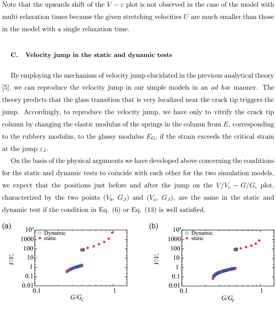
By employing two simulation models of crack propagation, the authors demonstrate the interrelation between static and dynamic boundary condition tests and isolate a universal condition that makes the velocity-jump outcomes identical in both.
What carries the argument
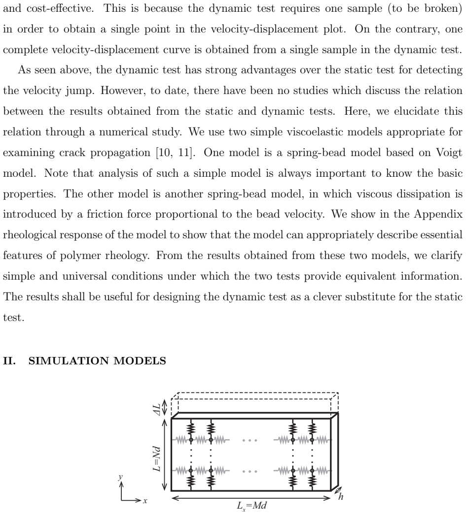
Two simulation models that compare crack propagation under static and dynamic boundary conditions while tracking velocity jumps and stress relaxation.
If this is right
- Dynamic tests become a reliable, single-sample substitute for static tests once the universal condition holds.
- Materials in which stress relaxation hides velocity jumps in static tests can still be characterized correctly by the dynamic method.
- Design of tough rubbers can proceed with fewer samples by using the dynamic test under the identified condition.
- The condition supplies a concrete guideline for deciding when dynamic-test data can be treated as equivalent to static-test data.
Where Pith is reading between the lines
- If the condition is confirmed experimentally, laboratories could shift to dynamic testing protocols to screen larger numbers of rubber formulations quickly.
- The same simulation approach might be applied to other fracture problems where boundary conditions alter relaxation rates.
- An analytic derivation of the condition, independent of the specific models, would allow its use without running new simulations for each material.
Load-bearing premise
The two simulation models correctly reproduce the stress relaxation and crack dynamics that occur in real materials.
What would settle it
Running both static and dynamic experiments on identical materials and verifying whether the observed velocity jumps match precisely when the models' universal condition is satisfied.
Figures
read the original abstract
Velocity jumps observed for crack propagation under a static boundary condition have been used as a controlling factor in developing tough rubbers. However, the static test requires many samples to detect the velocity jump. On the contrary, crack propagation performed under a dynamic boundary condition is timesaving and cost-effective in that it requires only a single sample to monitor the jump. In addition, recent experiments show that velocity jump occurs only in the dynamic test for certain materials, for which the velocity jump is hidden in the static test because of the effect of stress relaxation. Although the dynamic test is promising because of these advantages, the interrelation between the dynamic test and the more established static test has not been explored in the literature. Here, by using two simulation models, we elucidate this interrelation and clarify a universal condition for obtaining the same results from the two tests, which will be useful for designing the dynamic test.
Editorial analysis
A structured set of objections, weighed in public.
Referee Report
Summary. The paper uses two simulation models to investigate crack propagation in rubbers under static versus dynamic boundary conditions. It seeks to explain why velocity jumps appear in dynamic tests but can be masked by stress relaxation in static tests, and to identify a universal condition under which the two tests produce equivalent results, thereby enabling more efficient dynamic testing.
Significance. If the reported condition is indeed universal and independent of model details, the work would provide a practical bridge between established static testing protocols and faster dynamic alternatives, reducing sample requirements while correctly accounting for relaxation effects. The use of two distinct models to cross-check results is a positive step toward robustness.
major comments (2)
- The abstract asserts a 'universal condition' derived from two simulation models, yet provides no indication of tests across additional constitutive laws, discretization methods, or relaxation mechanisms. Without such checks or an analytic derivation free of model-specific assumptions, the universality claim does not follow from the presented evidence.
- The weakest assumption—that the two models faithfully capture the relevant physics so that simulation equivalence transfers to experiment—is not load-bearing only if the condition is shown to be model-independent; the current scope leaves open the possibility that the reported equivalence is an artifact of the chosen pair.
minor comments (1)
- Clarify in the introduction or methods how the two models differ in their treatment of stress relaxation under static boundaries.
Simulated Author's Rebuttal
We thank the referee for the detailed and constructive report. The comments highlight important limitations in the scope of our evidence for the reported condition. We address each major comment below and indicate the revisions we will make.
read point-by-point responses
-
Referee: The abstract asserts a 'universal condition' derived from two simulation models, yet provides no indication of tests across additional constitutive laws, discretization methods, or relaxation mechanisms. Without such checks or an analytic derivation free of model-specific assumptions, the universality claim does not follow from the presented evidence.
Authors: We agree that the evidence from only two models does not establish universality in the strict sense. In the revised manuscript we will replace the phrase 'universal condition' in the abstract and throughout the text with 'condition that holds across the two distinct models employed'. We will add an explicit paragraph in the discussion section stating that the result has been verified only for the continuum viscoelastic model and the discrete particle model used here, which differ in constitutive formulation, discretization, and relaxation implementation. We will also note the absence of an analytic derivation and the desirability of further checks with additional models. These changes will be made without altering the technical results. revision: yes
-
Referee: The weakest assumption—that the two models faithfully capture the relevant physics so that simulation equivalence transfers to experiment—is not load-bearing only if the condition is shown to be model-independent; the current scope leaves open the possibility that the reported equivalence is an artifact of the chosen pair.
Authors: The two models were deliberately selected to differ substantially (one is a finite-element implementation of a hyperelastic material with Prony-series relaxation; the other is a molecular-dynamics-style bead-spring network with a different potential and explicit chain dynamics). Their independent convergence on the same boundary-condition equivalence provides a non-trivial consistency check. Nevertheless, we accept that this does not prove model independence. In revision we will expand the methods and discussion sections to describe the differences between the models more explicitly and to qualify the transferability statement, making clear that experimental validation remains necessary. revision: yes
Circularity Check
No circularity: equivalence condition derived from direct comparison of two independent simulation models
full rationale
The paper's central claim rests on running two distinct simulation models under static and dynamic boundary conditions, then identifying a condition under which their outputs match. No equations, parameters, or results are shown to be defined in terms of the target equivalence itself, no fitted inputs are relabeled as predictions, and no load-bearing steps reduce to self-citations or ansatzes imported from prior author work. The derivation is therefore self-contained: the reported condition emerges from the model comparison rather than being presupposed by the modeling choices or by any internal redefinition.
Axiom & Free-Parameter Ledger
Reference graph
Works this paper leans on
-
[1]
Tsunoda, K., Busfield, J., Davies, C. & Thomas, A. Effect of materials variables on the tear behaviour of a non-crystallising elastomer. J. Mater. Sci. 35, 5187–5198 (2000). 14
work page 2000
-
[2]
Morishita, Y., Tsunoda, K. & Urayama, K. Velocity transition in the crack growth dynamics of filled elastomers: Contributions of nonlinear viscoelasticity. Physical Review E 93, 043001 (2016)
work page 2016
-
[3]
Morishita, Y., Tsunoda, K. & Urayama, K. Crack-tip shape in the crack-growth rate transition of filled elastomers. Polymer 108, 230–241 (2017)
work page 2017
-
[4]
Kubo, A. & Umeno, Y. Velocity mode transition of dynamic crack propagation in hypervis- coelastic materials: A continuum model study. Scientific Reports 7, 42305 (2017)
work page 2017
-
[5]
Sakumichi, N. & Okumura, K. Exactly solvable model for a velocity jump observed in crack propagation in viscoelastic solids. Scientific Reports 7, 8065 (2017)
work page 2017
-
[6]
Velocity jumps in crack propagation in elastomers: Relevance of a recent model to experiments
Okumura, K. Velocity jumps in crack propagation in elastomers: Relevance of a recent model to experiments. Journal of the Physical Society of Japan 87, 125003 (2018)
work page 2018
-
[7]
Kubo, A. et al. Dynamic glass transition dramatically accelerates crack propagation in rubber- like solids. Sci. Rep. (2019, submitted.)
work page 2019
-
[8]
Takei, A. & Okumura, K. Crack propagation in porous polymer sheets with different pore sizes. MRS Communications 1–6 (2018; http://dx.doi.org/10.1557/mrc.2018.222)
-
[9]
Tomizawa, T. & Okumura, K. Velocity jump in the crack propagation induced on a semi- crystalline polymer sheet by constant-speed stretching. Polymer (2019, in press)
work page 2019
-
[10]
Aoyanagi, Y. & Okumura, K. Stationary crack propagation in a two-dimensional visco-elastic network model. Polymer 120, 94–99 (2017)
work page 2017
-
[11]
Aoyanagi, Y. & Okumura, K. Crack propagation in a nonlinear viscoelastic modelcrack prop- agation in a nonlinear viscoelastic model. Langmuir (2019, under review)
work page 2019
-
[12]
Lake, G. & Thomas, A. The strength of highly elastic materials 300, 108–119 (1967)
work page 1967
-
[13]
Ferry, J. D. Viscoelastic properties of polymers (John Wiley & Sons, 1980). 15 Appendix
work page 1980
-
[14]
Details of the simulation models In the lattice network, the four nearest neighbor cites of the cite m = (i,j ) are specified by the indices m′ = (i − 1,j ), (i,j + 1), (i + 1,j ), and (i,j − 1), which are called ms with s = 1, 2, 3, and 4, respectively. The elongation vector ∆ xmm′ are defined as ∆ xmms = xm − xms − ds with d1 = (d, 0) = −d3 and d4 = (0,d ...
-
[15]
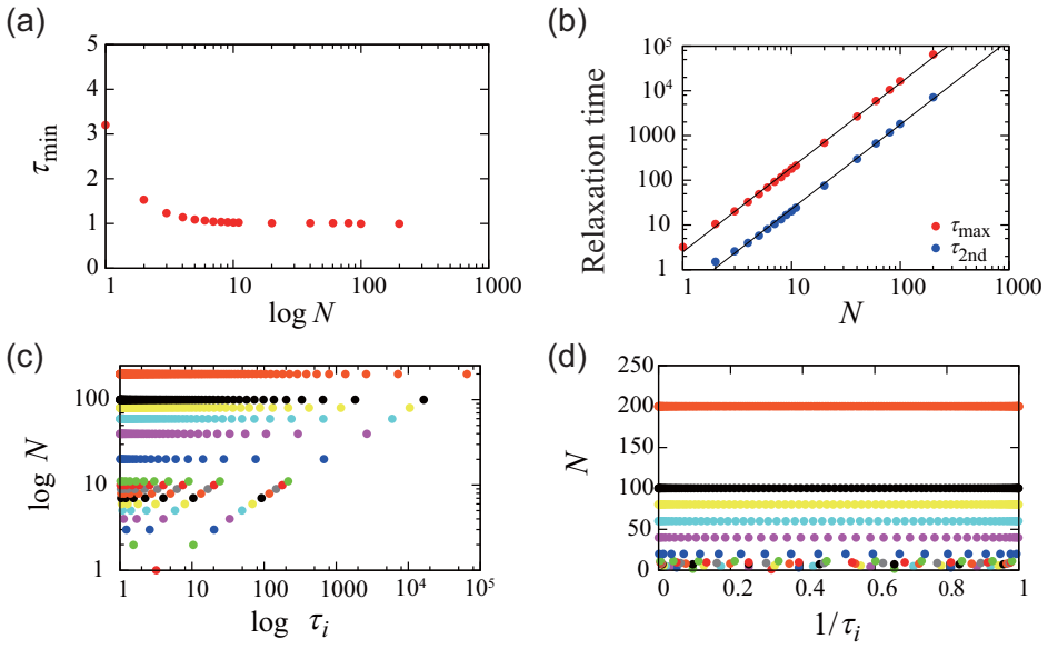
Distribution of Relaxation times in the simulation models To gain physical pictures of the models governed by Eqs. (4) and (5), we consider a creep test: we give a fixed stress σ0 suddenly at time t = 0 to observe the time development of the strain ε(t) after t = 0. In such a case, each column (in the y direction) behaves in the same way as its neighbors a...
-
[16]
For convenience, we first review and define rheological functions
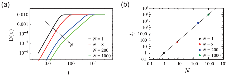
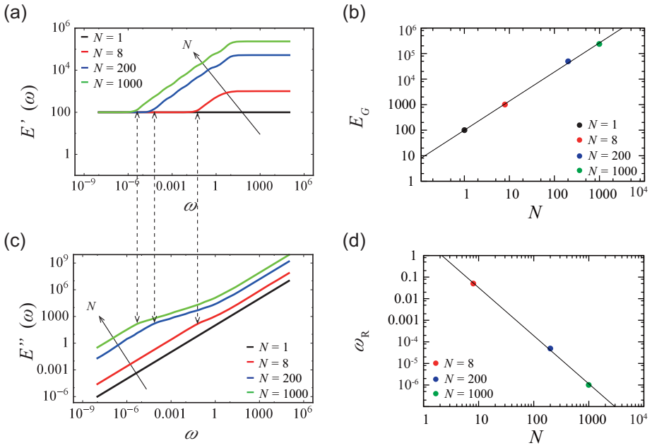
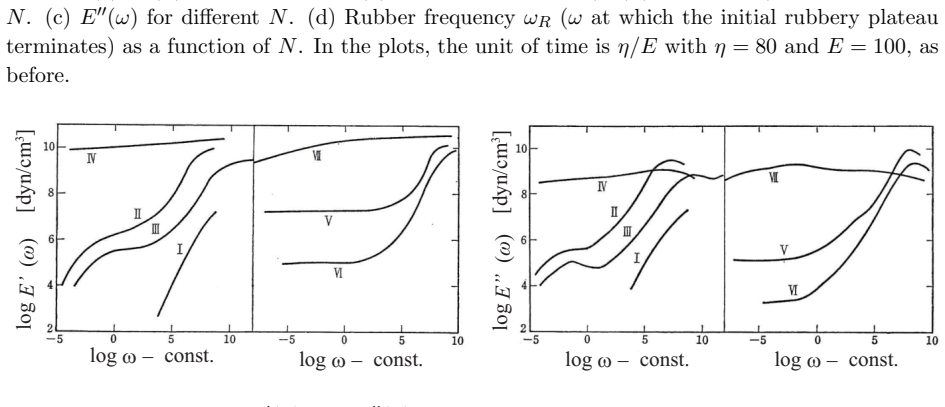
Rheological properties of the simulation models In this section, we demonstrate rheological properties of the two simulation models. For convenience, we first review and define rheological functions. The creep test is defined as follows: we give a fixed stress σ0 suddenly at time t = 0 to observe the time development of the strain ε(t) after t = 0. From ε(t) ...
discussion (0)
Sign in with ORCID, Apple, or X to comment. Anyone can read and Pith papers without signing in.