REVIEW 1 cited by
Characterisation of single microdischarges during plasma electrolytic oxidation of aluminium and titanium
T0 review · reviewed 2026-08-16 · deepseek-v4-flash
Pith's one-line read Using a 1 mm wire-tip anode, the authors show that aluminium produces longer-lived microdischarges and bubbles while titanium discharges are faster, and that KOH concentration controls whether titanium forms any PEO coating at all.
desk verdict First systematic Al vs Ti single-microdischarge comparison; the qualitative trends hold up, but fix the abstract/body crack contradiction and verify the pulse-to-bubble one-to-one assignment before accepting. read the letter →
The pith
A machine-rendered reading of the paper's core claim, the machinery that carries it, and where it could break.
The reading
Extended reading notes
Core claim
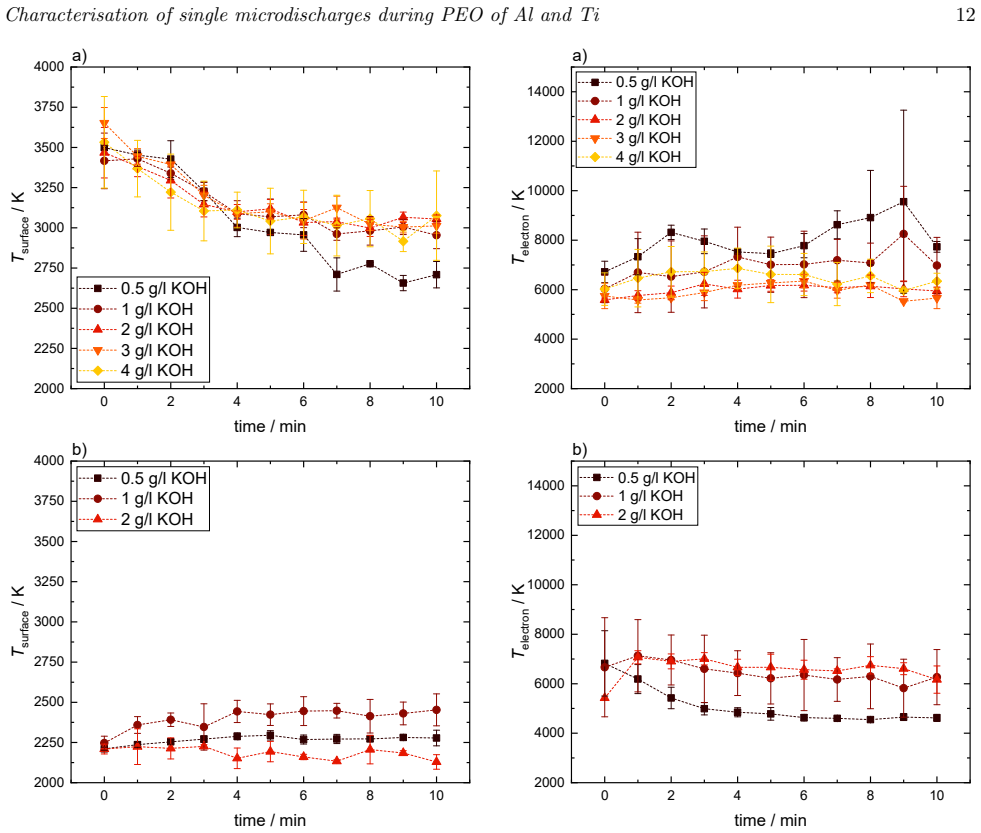
The study demonstrates that microdischarge behaviour is significantly influenced by the substrate material, treatment time, and electrolyte concentration, all of which impact the coating morphology. Under the conditions studied in this work, aluminium exhibits longer microdischarge and bubble lifetimes, with fewer cracks on the top layer of the coating, whereas titanium showed faster, shorter-lived bubbles due to more rapid microdischarge events. Supporting quantitative claims include surface temperatures of 2000-3750 K on Al and 2000-2500 K on Ti, electron temperatures of 5000-12200 K on Al and 4300-8600 K on Ti, and bubble pressures of 0.5-3 bar from Rayleigh-Plesset fitting.
Load-bearing premise
The assumption that each resolved current pulse corresponds to a single microdischarge on the 1 mm tip, and that the gas bubble imaged by the high-speed camera belongs to that same microdischarge. The paper states in §2 that triggering on the microdischarge current synchronizes measurements, and in §4.1 that 'Each current pulse represents an individual microdischarge,' citing Troughton. However, §4.1 also reports multiple simultaneous ignitions at some KOH concentrations, and §4.2 notes bubbles that could not be detected due to overlapping discharge events or noise. If current pulses are not single events, the reported lifetimes, radii, and pressure values would not be assignable to individual microdischarges.
Signed reviews
Editorial analysis
A structured set of objections, weighed in public.
Assumptions & free parameters
free parameters (5)
- C1 (Bremsstrahlung scaling factor in Eq. 7) =
fitted per spectrum, values not tabulated
- C2 (black-body scaling factor in Eq. 7) =
fitted per spectrum, values not tabulated
- Te (electron temperature) =
Al: 5000-12200 K; Ti: 4300-8600 K
- Ts (surface temperature) =
Al: 2600-3750 K; Ti: 2000-2500 K
- Bubble radius polynomial fit coefficients =
not stated
assumptions (8)
- domain assumption n0 >> ni approximately ne(max) of 1e17 cm-3, so electron-ion free-free and free-bound terms are neglected in Eq. (2).
- domain assumption The electron energy distribution function is Maxwellian and the elastic scattering cross-section has a weak energy dependence.
- domain assumption The hot substrate surface radiates as a black body with emission coefficient epsilon = 1.
- domain assumption Liquid water absorption follows the Beer-Lambert law with literature values of alpha(lambda) over a path of about 1 cm.
- domain assumption The gas bubble can be modeled by the spherical Rayleigh-Plesset equation with an incompressible Newtonian liquid, no gravity, and constant properties.
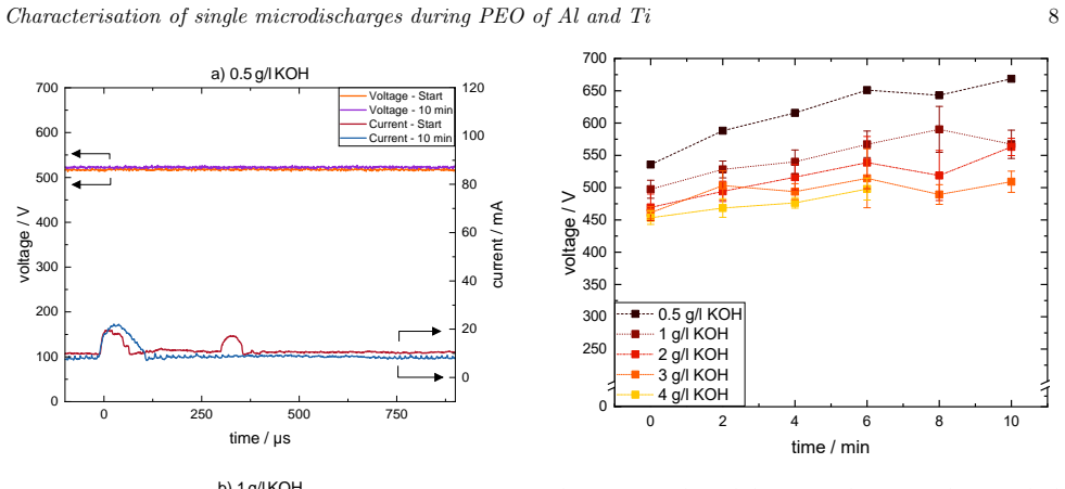
- domain assumption Electrolyte conductivity remains constant over the 10-minute treatment, so voltage rise indicates coating resistance growth.
- domain assumption The 1 mm wire-tip anode under 1.27 A/cm2 produces isolated microdischarges representative of PEO.
- standard math The continuum emission formulas from the cited literature, such as Bílek et al. and Burm, correctly describe the discharge radiation.
Cite this review
Pith. "Pith review of Characterisation of single microdischarges during plasma electrolytic oxidation of aluminium and titanium." pith.science (2026). https://pith.science/paper/H2DZML4X
@misc{pith2026250412139,
  author       = {Pith},
  title        = {Pith review of: Characterisation of single microdischarges during plasma electrolytic oxidation of aluminium and titanium},
  year         = {2026},
  howpublished = {\url{https://pith.science/paper/H2DZML4X}},
  note         = {Machine review of arXiv:2504.12139}
}
read the original abstract
Plasma electrolytic oxidation (PEO) is a technique used to create oxide-ceramic coatings on lightweight metals, such as aluminium, magnesium, and titanium. PEO is known for producing coatings with high corrosion resistance and strong adhesion to the substrate. The process involves generating short-lived microdischarges on the material surface through anodic dielectric breakdown in a conductive aqueous solution. To investigate single microdischarges during PEO, a single microdischarge setup was developed, where the active anode surface is reduced to the tip of a wire with a diameter of 1 mm. In this work the focus is on the effect of electrolyte concentration, anode material, and electrical parameters on the microdischarges. The electrolyte is composed of distilled water with varying concentrations of potassium hydroxide (0.5 - 4 g/l). High-speed optical measurements are conducted to gain insights into the formation and temporal evolution of individual microdischarges and the induced gas bubble formation. Optical emission spectroscopy is used to estimate surface and electron temperatures by fitting Bremsstrahlung and Planck's law to the continuum spectrum of the microdischarges. To evaluate the impact of the microdischarges on coating morphology, the resulting oxide layers on the metal tips are analysed using scanning electron microscopy. The study demonstrates that microdischarge behaviour is significantly influenced by the substrate material, treatment time, and electrolyte concentration, all of which impact the coating morphology. Under the conditions studied in this work, aluminium exhibits longer microdischarge and bubble lifetimes, with fewer cracks on the top layer of the coating, whereas titanium showed faster, shorter-lived bubbles due to more rapid microdischarge events.
Figures


Figures from the paper (7 more)




Forward citations
Cited by 1 Pith paper
-
Electron and gas temperature-driven chemistry during microdischarges formed in water vapour bubbles
A 0-D model with a new reaction scheme shows that both electron impact and high-temperature neutral reactions control the chemistry of microdischarges in water vapour bubbles.
Reference graph
Works this paper leans on
-
[1]
Introduction: plasma electrolytic oxidation Light metals like aluminium, titanium, magnesium, and their alloys are extensively used in transport and medical applications [1, 2]. With the densities of alu- minium (2.7 g/cm 3) and magnesium (1.7 g/cm 3) be- ing less than one-third that of iron (8.9 g/cm 3), they are suitable for weight reduction in car manu...
-
[2]
This system was originally described in de- tail in the work of Bracht [27]
Experimental setup An experimental system specialised for the study of single microdischarges (SMDs) during PEO has been developed. This system was originally described in de- tail in the work of Bracht [27]. The reduction of the anode/substrate to the tip of a wire with a diameter of 1 mm ensures ignitions of mainly single discharges on the wire tip, eac...
-
[3]
Diagnostic methods Different diagnostic tools are applied to observe the substrate tip and investigate individual microdis- charges and bubble dynamics during the PEO process (sections 3.1, 3.2). In addition, a post treatment anal- Characterisation of single microdischarges during PEO of Al and Ti 4 ysis is performed with a scanning electron microscope (S...
-
[4]
This results in the final ex- pression for the intensity of Bremsstrahlung: Ien ff (λ,T e) =C ′ 1 (kBTe) 3 2 λhc " 1 + hc λkBTe 2 + 1 # × exp −hc λkBTe (5) As previously noted, thermal radiation from the anode surface also contributes to the continuum radia- tion. For simplicity, a black body radiator is assumed, with an intensity calculated using Planck’...
-
[5]
Results and discussion This section is divided into four parts comparing the effect of electrolyte concentration and treatment time on an aluminium (Al) and a titanium (Ti) substrate during a PEO process. The first part investigates the current and voltage behaviour during the PEO process, followed by an analysis of bubble dynamics in relation to microdis...
-
[6]
Gibson: https://orcid.org/0000-0002-1082- 4359
ORCID iDs Jan-Luca Gembus: https://orcid.org/0009-0002-1263- 9218 Vera Bracht: https://orcid.org/0000-0003-4623-7532 Lars Sch¨ ucke: https://orcid.org/0000-0002-7991-853X Peter Awakowicz: https://orcid.org/0000-0002-8630- 9900 Andrew R. Gibson: https://orcid.org/0000-0002-1082- 4359
-
[7]
2. 3. bubble discharge Figure 6. Time-resolved current measurement with the corresponding bubble radius for an aluminium substrate and 1 g/l of KOH. Bubble formation is shown in the top images in b). The numbers correspond to the marked areas in the graphs below. a) shows the bubble at the beginning, and b) after 10 minutes of operation. which is consiste...
-
[8]
3. 4. bubble bubble bubbledischarge bubble discharge 2.1. 3. 4. Figure 7. Time-resolved current measurement with the corresponding bubble images for a titanium substrate. Bubble growth and collapse are seen in the top images, where the numbers correspond to the highlighted time points in the graphs below. a) presents the beginning of the process for 1 g/l...
Show all 53 references
-
[9]
Transient atmospheric plasmas: from plasmas to liquids to solids
Conclusion and outlook The present study has investigated the influence of different KOH electrolyte concentrations on microdis- charge behaviour during plasma electrolytic oxidation (PEO) of aluminium (Al) and titanium (Ti) substrates. By employing a single microdischarge set...
2000
-
[10]
What is plasma electrolytic oxidation (peo)? [white paper],
Keronite, “What is plasma electrolytic oxidation (peo)? [white paper],” 2018. Accessed: 2022-12-07
2018
-
[11]
Review of plasma electrolytic oxidation of titanium substrates: Mechanism, properties, applications and limitations,
M. Aliofkhazraei, D. Macdonald, E. Matykina, E. Parfenov, V. Egorkin, J. Curran, S. Troughton, S. Sinebryukhov, S. Gnedenkov, T. Lampke, F. Simchen, and H. Nabavi, “Review of plasma electrolytic oxidation of titanium substrates: Mechanism, properties, applications and limitati...
2021
-
[12]
Dong, Preface
H. Dong, Preface. Woodhead Publishing Series in Metals and Surface Engineering, Woodhead Publishing, 2010
2010
-
[13]
Recent advances in light metals and man- ufacturing for automotive applications,
A. A. Luo, “Recent advances in light metals and man- ufacturing for automotive applications,” CIM Journal , vol. 12, no. 3, pp. 79–87, 2021
2021
-
[14]
Titanium Coatings and Surface Modifications: Toward Clinically Useful Bioactive Implants,
A. Civantos, E. Mart´ ınez-Campos, V. Ramos, C. Elvira, A. Gallardo, and A. Abarrategi, “Titanium Coatings and Surface Modifications: Toward Clinically Useful Bioactive Implants,” ACS Biomaterials Science & Engineering, vol. 3, pp. 1245–1261, July 2017. Publisher: American Che...
2017
-
[15]
Evolution of anodised titanium for implant applications,
J. Alipal, T. C. Lee, P. Koshy, H. Z. Abdullah, and M. I. Idris, “Evolution of anodised titanium for implant applications,” Heliyon, vol. 7, no. 7, p. e07408, 2021
2021
-
[16]
Ferraris, ed., Surface Engineering of Light Alloys
S. Ferraris, ed., Surface Engineering of Light Alloys . MDPI, 2021
2021
-
[17]
I. J. Polmear, J.-F. Nie, M. Qian, and D. StJohn, Light alloys: metallurgy of the light metals . Oxford: Butterworth-Heinemann, an imprint of Elsevier, fifth edition ed., 2017. OCLC: ocn957503518
2017
-
[18]
Synthesis of bioactive glass-based coating by plasma electrolytic oxidation: Untangling a new deposition pathway toward titanium implant surfaces,
R. C. Costa, J. G. Souza, J. M. Cordeiro, M. Bertolini, E. D. De Avila, R. Landers, E. C. Rangel, C. A. Fortulan, B. Retamal-Valdes, N. C. Da Cruz, M. Feres, and V. A. Bar˜ ao, “Synthesis of bioactive glass-based coating by plasma electrolytic oxidation: Untangling a new depos...
2020
-
[19]
Jiang and Y
B. Jiang and Y. Wang, 5 - Plasma electrolytic oxidation treatment of aluminium and titanium alloys , pp. 110–
-
[20]
In-situ control of microdischarge characteristics in unipolar pulsed plasma electrolytic oxidation of aluminum,
P. Hermanns, S. Boeddeker, V. Bracht, N. Bibinov, and P. Awakowicz, “In-situ control of microdischarge characteristics in unipolar pulsed plasma electrolytic oxidation of aluminum,” Journal of Physics D: Applied Physics, vol. 53, p. 435204, Oct. 2020
2020
-
[21]
Morphological analysis of plasma electrolytic oxidation coatings formed on Ti6Al4V alloys manufactured by electron beam powder bed fusion,
C. A. Vargas, A. A. Zuleta, C. A. Botero, L. M. Baena, J. G. Casta˜ no, M. A. G´ omez, and J. A. Tamayo, “Morphological analysis of plasma electrolytic oxidation coatings formed on Ti6Al4V alloys manufactured by electron beam powder bed fusion,” Heliyon, vol. 9, p. e19289, Sept. 2023
2023
-
[22]
Production of anti-corrosion coatings on light alloys (al, mg, ti) by plasma-electrolytic oxidation (PEO),
R. O. Hussein and D. O. Northwood, “Production of anti-corrosion coatings on light alloys (al, mg, ti) by plasma-electrolytic oxidation (PEO),” in Developments in Corrosion Protection (M. Aliofkhazraei, ed.), ch. 11, Rijeka: IntechOpen, 2014
2014
-
[23]
Bioactive plasma electrolytic oxida- tion coatings—The role of the composition, microstruc- ture, and electrochemical stability,
M. Mohedano, R. Guzman, R. Arrabal, J. L´ opez Lacomba, and E. Matykina, “Bioactive plasma electrolytic oxida- tion coatings—The role of the composition, microstruc- ture, and electrochemical stability,” Journal of Biomed- ical Materials Research Part B: Applied Biomaterials ,...
2013
-
[24]
Bioactivity Performance of Pure Mg after Plasma Electrolytic Oxidation in Silicate-Based Solutions,
Y. Husak, J. Michalska, O. Oleshko, V. Korniienko, K. Grundsteins, B. Dryhval, S. Altundal, O. Mishchenko, R. Viter, M. Pogorielov, and W. Simka, “Bioactivity Performance of Pure Mg after Plasma Electrolytic Oxidation in Silicate-Based Solutions,” Molecules, vol. 26, p. 2094, ...
2021
-
[25]
Plasma Electrolytic Oxidation Coatings on Aluminum Alloys: Microstructures, Properties, and Applications,
X. Huang, “Plasma Electrolytic Oxidation Coatings on Aluminum Alloys: Microstructures, Properties, and Applications,” Modern Concepts in Material Science , vol. 2, Nov. 2019
2019
-
[26]
Plasma Electrolytic Oxidation (PEO) Process—Processing, Properties, and Applications,
S. Sikdar, P. V. Menezes, R. Maccione, T. Jacob, and P. L. Menezes, “Plasma Electrolytic Oxidation (PEO) Process—Processing, Properties, and Applications,” Nanomaterials, vol. 11, p. 1375, May 2021
2021
-
[27]
Therefore, it is assumed that a rise in volt- age indicates an increase in coating resistance
confirmed this stability for an Al substrate, observ- ing no significant changes in pH or conductivity over that period. Therefore, it is assumed that a rise in volt- age indicates an increase in coating resistance. Bracht’s study [27] also highlighted differences in coating t...
-
[28]
An investigation of ceramic coating growth mechanisms in plasma electrolytic oxidation (PEO) processing,
R. Hussein, X. Nie, and D. Northwood, “An investigation of ceramic coating growth mechanisms in plasma electrolytic oxidation (PEO) processing,” Electrochimica Acta, vol. 112, pp. 111–119, Dec. 2013
2013
-
[29]
A review of recent work on discharge characteristics during plasma electrolytic oxidation of various metals,
T. W. Clyne and S. C. Troughton, “A review of recent work on discharge characteristics during plasma electrolytic oxidation of various metals,” International Materials Reviews, vol. 64, no. 3, pp. 127–162, 2019
2019
-
[30]
Synchronised electrical monitoring and high speed video of bubble growth associated with individual discharges during plasma electrolytic oxidation,
S. Troughton, A. Nomin´ e, A. Nomine, G. Henrion, and T. Clyne, “Synchronised electrical monitoring and high speed video of bubble growth associated with individual discharges during plasma electrolytic oxidation,” Applied Surface Science, vol. 359, pp. 405–411, 2015
2015
-
[31]
Introduction to plasma electrolytic oxidation—an overview of the process and applications,
F. Simchen, M. Sieber, A. Kopp, and T. Lampke, “Introduction to plasma electrolytic oxidation—an overview of the process and applications,” Coatings, vol. 10, no. 7, 2020
2020
-
[32]
Electron–neutral bremsstrahlung radiation finger- prints the initial stage of nanosecond discharge in liquid water,
P. B´ ılek, J. Tungli, T. Hoder, M. ˇSimek, and Z. Bonaven- tura, “Electron–neutral bremsstrahlung radiation finger- prints the initial stage of nanosecond discharge in liquid water,” Plasma Sources Science and Technology , vol. 30, p. 04LT01, apr 2021
2021
-
[33]
Plasma electrolytic oxidation (PEO): An alternative to conventional anodization process,
R. R. Lucas, R. C. Sales-Contini, F. J. Da Silva, E. C. Botelho, and R. P. Mota, “Plasma electrolytic oxidation (PEO): An alternative to conventional anodization process,” AIMS Materials Science , vol. 11, no. 4, pp. 684–711, 2024
2024
-
[34]
Spectroscopic study of electrolytic plasma and discharging behaviour during the plasma electrolytic oxidation (PEO) process,
R. O. Hussein, X. Nie, D. O. Northwood, A. Yerokhin, and A. Matthews, “Spectroscopic study of electrolytic plasma and discharging behaviour during the plasma electrolytic oxidation (PEO) process,” Journal of Physics D: Applied Physics, vol. 43, no. 10, p. 105203, 2010
2010
-
[35]
Characterization of oxide coating grown by plasma electrolytic oxidation (PEO) at different times on aluminum alloy AA2024- T3,
R. R. Lucas, R. P. Mota, A. B. R. M. Abrah˜ ao, E. C. Botelho, and R. C. M. Sales-Contini, “Characterization of oxide coating grown by plasma electrolytic oxidation (PEO) at different times on aluminum alloy AA2024- T3,” MRS Communications , vol. 12, pp. 266–271, Apr. 2022
2022
-
[36]
Bracht, F
V. Bracht, F. Kogelheide, S. Gr¨ oger, P. Hermanns, S. B¨ oddeker, N. Bibinov, and P. Awakowicz, “Modi- fications of an electrolytic aluminum oxide film under the treatment with microdischarges during plasma elec- trolytic oxidation, a self-organized dielectric barrier dis- ch...
2021
-
[37]
Effect of individual discharge cascades on the microstructure of plasma electrolytic oxidation coatings,
S. Troughton, A. Nomin´ e, J. Dean, and T. Clyne, “Effect of individual discharge cascades on the microstructure of plasma electrolytic oxidation coatings,” Applied Surface Science, vol. 389, pp. 260–269, Dec. 2016
2016
-
[38]
Bracht, Characterisation of single microdischarges during plasma electrolytic oxidation of aluminium
V. Bracht, Characterisation of single microdischarges during plasma electrolytic oxidation of aluminium . doctoralthesis, Ruhr-Universit¨ at Bochum, Univer- Characterisation of single microdischarges during PEO of Al and Ti 16 sit¨ atsbibliothek, 2022
2022
-
[39]
Dynamics of bubbles created by plasma in heptane for micro-gap conditions,
A. Hamdan, C. Noel, F. Kosior, G. Henrion, and T. Belmonte, “Dynamics of bubbles created by plasma in heptane for micro-gap conditions,” The Journal of the Acoustical Society of America , vol. 134, pp. 991–1000, Aug. 2013
2013
-
[40]
On stability of time marching in numerical solutions of rayleigh-plesset equation for ultrasonic cavitation,
W. Y. Tey, H. Alehossein, Z. Qin, K. M. Lee, H. S. Kang, and K. Q. Lee, “On stability of time marching in numerical solutions of rayleigh-plesset equation for ultrasonic cavitation,” IOP Conference Series: Earth and Environmental Science , vol. 463, p. 012117, mar 2020
2020
-
[41]
V. Y. Ushakov, V. Y. Ushakov, V. F. Klimkin, and S. M. Korobeynikov, Impulse Breakdown of Liquids . Springer, 2007
2007
-
[42]
Characterization of a transient spark micro-discharge in nitrogen using simultaneous two- wavelength diagnostics,
S. Gr¨ oger, M. Fiebrandt, M. Hamme, N. Bibinov, and P. Awakowicz, “Characterization of a transient spark micro-discharge in nitrogen using simultaneous two- wavelength diagnostics,” Measurement Science and Technology, vol. 31, p. 075501, July 2020
2020
-
[44]
Kunze, Introduction To Plasma Spectroscopy
H.-J. Kunze, Introduction To Plasma Spectroscopy . Springer, 2009
2009
-
[45]
Continuum radiation in a high pressure argon–mercury lamp,
K. Burm, “Continuum radiation in a high pressure argon–mercury lamp,” Plasma Sources Science and Technology, vol. 13, p. 387, may 2004
2004
-
[46]
Boltzmann equation analysis of electron-molecule collision cross sections in water vapor and ammonia,
M. Yousfi and M. D. Benabdessadok, “Boltzmann equation analysis of electron-molecule collision cross sections in water vapor and ammonia,” Journal of Applied Physics , vol. 80, no. 12, pp. 6619–6630, 1996
1996
-
[47]
Optical constants of water in the 200-nm to 200-µm wavelength region,
G. M. Hale and M. R. Querry, “Optical constants of water in the 200-nm to 200-µm wavelength region,” Appl. Opt., vol. 12, pp. 555–563, Mar 1973
1973
-
[48]
Scanning electron microscopy (SEM) and transmission electron microscopy (TEM) for materials characterization,
B. Inkson, “Scanning electron microscopy (SEM) and transmission electron microscopy (TEM) for materials characterization,” in Materials Characterization Using Nondestructive Evaluation (NDE) Methods , pp. 17–43, Elsevier, 2016
2016
-
[49]
Hermanns, Charakterisierung und Prozessoptimierung industriell relevanter Mikroplasmen
P. Hermanns, Charakterisierung und Prozessoptimierung industriell relevanter Mikroplasmen . doctoralthesis, Ruhr-Universit¨ at Bochum, Universit¨ atsbibliothek, 2020
2020
-
[50]
Shackelford, Y.-H
J. Shackelford, Y.-H. Han, S. Kim, and S.-H. Kwon, CRC Materials Science and Engineering Handbook (4th Ed.) . Taylor & Francis Group, LLC, 2016
2016
-
[51]
Effect of current mode on the plasma discharge, microstruc- ture and corrosion resistance of oxide coatings produced on 1100 aluminum alloy by plasma electrolytic oxida- tion,
R. O. Hussein, X. Nie, and D. O. Northwood, “Effect of current mode on the plasma discharge, microstruc- ture and corrosion resistance of oxide coatings produced on 1100 aluminum alloy by plasma electrolytic oxida- tion,” in MATERIALS CHARACTERISATION 2019 , (Lisbon, Portugal)...
2019
-
[52]
Spectroscopic study of plasma during electrolytic oxidation of magnesium- and aluminium-alloy,
J. Jovovi´ c, S. Stojadinovi´ c, N. M.ˇSiˇ sovi´ c, and N. Konjevi´ c, “Spectroscopic study of plasma during electrolytic oxidation of magnesium- and aluminium-alloy,” Journal of Quantitative Spectroscopy and Radiative Transfer , vol. 113, no. 15, pp. 1928–1937, 2012
1928
-
[53]
Char- acterisation of discharge events during plasma elec- trolytic oxidation,
C. Dunleavy, I. Golosnoy, J. Curran, and T. Clyne, “Char- acterisation of discharge events during plasma elec- trolytic oxidation,” Surface and Coatings Technology , vol. 203, pp. 3410–3419, Aug. 2009. Characterisation of single microdischarges during PEO of Al and Ti S1 Suppl...
2009
-
[154]
Woodhead Publishing Series in Metals and Surface Engineering, Woodhead Publishing, 2010
2010
Reviewed August 16, 2026 · model on record in the stance chip above.
Discussion (0). Continue with ORCID to comment.