REVIEW 4 major objections 6 minor 30 references
Reconfigurable Tendon-Driven Robots: Eliminating Inter-segmental Coupling via Independently Lockable Joints
T0 review · 4 major / 6 minor · reviewed 2026-08-06 · deepseek-v4-flash
Pith's one-line read Lockable joints eliminate inter-segmental coupling in tendon-driven robots, giving the same structure a larger reachable workspace and letting a seven-joint prototype run on only six motors.
desk verdict A plausible, working lockable-joint tendon robot with a real hardware contribution, undercut by an unmeasured rigidity assumption and a validation-error inconsistency. read the letter →
The pith
A machine-rendered reading of the paper's core claim, the machinery that carries it, and where it could break.
The reading
What carries the argument
The load-bearing mechanism is the dead-point lockable joint together with the time-phased actuation strategy built on it. Each joint pairs a base link with an asymmetric trigger and a toothed slider: pulling the trigger with a locking tendon pushes the slider into engagement with the link below, and because the resulting force line passes through the trigger's rotation axis the mechanism settles into a dead point that keeps the joint locked with no power input; releasing the latch lets implanted magnets retract the slider and free the joint. Under the motion strategy only the targeted joints are unlocked and driven by the common tendon set, so no segment's motion is transmitted to its neighbours. This mechanism is also what carries the reachable-workspace proof, because locking arbitrary subsets of joints samples a much larger set of joint-angle combinations than the equal-angle constant-curvature motion available to a conventional TDR.
What would settle it
Lock one joint of the prototype, apply the maximum tendon tensions used in the demonstrations along with the distal payload, and track the joint angle with an optical tracker while the lock is engaged and while it is switched; angular drift beyond the reported model error of about 0.06 degrees would contradict the rigid-lock premise and with it the time-phased motion strategy.
Extended reading notes
Core claim
The paper's central discovery is that the inter-segmental motion coupling usually taken as the cost of adding segments to a tendon-driven robot can be eliminated mechanically rather than compensated by control. In the proposed reconfigurable tendon-driven robot, every joint contains a trigger-and-slider latch that meshes with the next link and rests in a dead-point configuration, so the locked state holds without continuous power; a pair of antagonistic tendons switches each joint's locked or free state on command. Motion proceeds in phases: unlock the targeted joints, actuate them with the single shared set of driving tendons, and lock them again, with locked joints treated as rigid bodies. Lemma 1 formalizes the payoff by showing that, with the same structure and actuation module, the RTR's reachable workspace strictly contains the workspace of a conventional TDR. The statics model, which propagates tendon forces and moments from the distal joint to the base and includes an exponential tendon-friction term, predicts the measured joint angles across several locking patterns and payloads with a reported worst mean error below 0.064 degrees.
Load-bearing premise
The argument assumes that a mechanically locked joint holds its angle as a rigid body and that locking or unlocking it does not disturb the robot's pose, even though the paper's own statics model shows tendon and payload forces acting on every joint.
Editorial extensions
If this is right
- With the same structure and actuation module, the RTR's reachable workspace strictly contains that of a conventional TDR: $W_{TDR} \subsetneq W_{RTR}$, so the conventional robot is a special case.
- Dexterity grows with reconfigurability: for a fixed target point, increasing the number of movable segments from 3 to 6 raises the maximum planar dexterity index $D_p$ from 21.85% to 66.75%.
- Control becomes time-phased instead of coordinated: a seven-joint RTR prototype carries out obstacle-avoidance and target-alignment sequences with only six motors and one set of driving tendons.
- The static model predicts joint angles under different locking patterns, tendon tensions, and distal payloads with reported mean error below 0.064 degrees, making the locked-rigid assumption testable in practice.
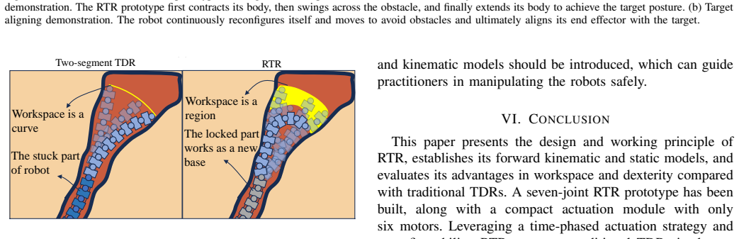
- In confined spaces such as surgical access paths, locking the proximal joints lets them act as a new base so the distal end keeps a region-shaped workspace instead of degrading to a curve.
Reading between the lines
- If locked joints are as stiff as assumed, the paper's purely kinematic workspace proof should extend to a static claim: under a given payload, the set of equilibrium postures of the RTR should be at least as large as that of a conventional TDR with the same actuation module; the paper does not prove this loaded version.
- The ideal-condition result that free joints follow the constant-curvature model suggests a cheap motion planner: search over lock schedules and segment-length proportions rather than over all joint angles, an algorithm the authors identify as needed but do not provide.
- A quantitative miniaturization study would sharpen the scaling discussion: estimating the minimum tooth and slider size for a reliable dead point would say how far the concept can go toward surgical-scale robots.
- The dexterity map for a fixed target points toward online reconfiguration: the same idea could be turned into a controller that adjusts the locked/free distribution as the robot approaches a target to increase the number of approach directions, something the paper demonstrates offline only.
Signed reviews
Editorial analysis
A structured set of objections, weighed in public.
Referee Report
Summary. The manuscript presents a reconfigurable tendon-driven robot (RTR) with individually lockable joints that can be set (locked/free) via antagonistic tendons. The proposed design uses a single set of four driving tendons and a six-motor actuation pack to drive a seven-joint spatial arm; by locking non-target joints, the authors claim inter-segmental coupling is fundamentally eliminated. The paper derives a free-body static model (Eqs. 1-11), a constant-curvature-based kinematic model (Eqs. 12-19), a workspace comparison with a traditional TDR (Lemma 1), and a dexterity analysis (Section III.D). Experimental validation of the static model (Section IV.A) and two qualitative demonstrations (Section IV.B) are reported.
Significance. If the lockable-joint mechanism performs as assumed, the RTR concept would allow a large-DoF tendon-driven arm to be controlled with a small actuator pack, with potential advantages in dexterity and workspace over constant-curvature single-segment TDRs. The statics derivation is a standard free-body formulation, the workspace proof is mathematically clean under its stated assumptions, and the prototype demonstrations (Fig. 8) provide useful feasibility evidence. However, the validation data are internally inconsistent, and the load-bearing assumption of rigid locked joints is not experimentally characterized. With those points addressed, the contribution could be of interest to the continuum-robotics community.
major comments (4)
- [Section IV.A, Table IV] The text claims 'the worst mean error and its standard deviation of all joints less than 0.064 and 0.035 degrees, respectively,' but Table IV lists mean errors ranging from 0.178° to 1.170° and standard deviations from 5.973° to 13.15°. This is a direct numerical contradiction. If the table is correct, the static model's accuracy is far worse than claimed; if the text is correct, the table entries are erroneous. The authors must resolve this discrepancy and report the actual error statistics, including per-joint errors, before the validation claim can be assessed.
- [Section II.B and Section II.A] The central 'fundamentally eliminates inter-segmental coupling' claim rests on the assumptions that a dead-point-locked joint behaves as a perfect rigid body and that locking/unlocking switching does not change the robot's posture. These assertions are stated qualitatively ('quite stable within the tolerance of the material,' 'considered negligible') without measurement. The statics model itself (Eqs. 8-10) shows that tendon contact forces act on every intermediate joint, and the motion strategy keeps driving tendons tight during locking. A characterization of holding torque vs. deflection (backlash) and of the posture disturbance during lock-state switching is needed to support the decoupling claim; without it, the alleged fundamental elimination is not demonstrated.
- [Section III.C, Lemma 1] The proof compares RTR's workspace to a traditional TDR defined as a single-segment constant-curvature arm (Eqs. 23-24). This is a limited baseline: a multi-segment TDR with independent tendon sets, as discussed in the Introduction, can also achieve non-constant-curvature shapes. The claim that RTR has a larger workspace than 'the traditional TDR' should be either restricted to the same actuation constraints (one set of driving tendons) or compared against the multi-segment TDR with the same total number of motors. In addition, the workspace simulations in Fig. 4 do not list the link lengths, joint ranges, and tendon routing used, which limits reproducibility.
- [Section IV.A, model parameters] The static model depends on the backbone stiffness KN (Eq. 2) and the friction coefficient μ (Eq. 28). μ is calibrated from a single experimental condition (no locked joints, no external force), and KN is not reported as an identified parameter or given a value. Because the validation is performed on the same prototype used for calibration, a leave-one-out cross-validation or at least a sensitivity analysis over plausible μ and KN ranges would be needed to show the model is truly predictive rather than fitted.
minor comments (6)
- [Section III.A] The notation 'bx' for a skew-symmetric matrix is used without definition; please define it (e.g., the hat operator).
- [Section III.C] The homogeneous transformation notation in Eq. (21) and around appears with inconsistent frame subscripts; make the frame conventions uniform.
- [Section IV.A] The sentence 'The calibrated μ was found to be 0.085' should specify the optimization criterion (e.g., least squares on which joint angles) and the number of experiments used for calibration.
- [Section VI] The conclusion repeats the '0.064 ± 0.035 degrees' figure without referencing the table; please ensure it matches the corrected validation numbers.
- [Section I] The phrase 'fundamentally eliminates inter-segmental coupling' is used in the abstract and conclusion; consider softening to 'substantially reduces' until the rigidity of locked joints is experimentally demonstrated.
- [Fig. 5(b)] The dexterity map's color scale is not defined clearly; add a colorbar with units and indicate the maximum point in the text.
Circularity Check
One fitted parameter is validated on its own calibration row and the accuracy claim contradicts Table IV; the central workspace/decoupling claims are not circular.
-
fitted input called prediction
[Section IV.A (Static Model Validation), Table IV]
"The calibrated µ was found to be 0.085 by using the experimental data from the robot without any locked joint or external force. Posture errors between the experimental and simulated data are shown in Fig. 7 (b) and Table IV. The results indicate that the model is accurate with the worst mean error and its standard deviation of all joints less than 0.064 and 0.035 degrees, respectively."
The static model contains one fitted parameter, µ, calibrated on the no-locked/no-external-force condition. That condition is listed as the first row of Table IV (f1=0, f2=0.98 N, fex=0, error 0.5105°±7.057°), which is then presented as validation evidence. For that row, the comparison is in-sample rather than an out-of-sample prediction, so the reported aggregate accuracy includes the calibration datum. Moreover, Table IV's own mean errors (0.5105°, 1.170°, 1.038°) contradict the text's claim that the worst mean error is below 0.064°, further undermining the validation statement. The other rows are independent of the µ fit, so the circularity is partial and does not extend to the workspace or decoupling claims.
full rationale
The paper's central derivations are largely self-contained. Lemma 1's workspace comparison is a set-inclusion consequence of the definitions: the RTR workspace is written as the union over independent joint angles (Eq. 22) while the traditional TDR workspace is the constant-curvature equal-angle subset (Eq. 23), so W_TDR ⊂ W_RTR follows by construction rather than by fitting. The constant-curvature premise for kinematics is supported by the paper's own static force-balance simulation (Table II) and by prior work [22], but the current derivation does not assume the conclusion. The static model is a free-body derivation (Eqs. 1-11) with one fitted friction coefficient; the only partial circularity is that the calibration condition is included in the validation table and the reported accuracy is contradicted by that table. Self-citations [22] and [23] are extensions of prior models, not load-bearing substitutes for independent evidence. The 'eliminates inter-segmental coupling' claim rests on the unmeasured rigidity of locked joints during switching and tendon loads; that is an unsupported physical premise and a correctness risk, but it is not a circular derivation. Overall, aside from the calibration-row validation issue, the derivation chain is not circular.
Assumptions & free parameters
free parameters (2)
- Friction coefficient mu =
0.085
- Backbone torsional stiffness KN per joint =
not disclosed
assumptions (5)
- ad hoc to paper Locked joints are rigid bodies with no backlash, and lock-state switching does not change the robot's posture
- domain assumption Free sub-segments follow the constant-curvature model under ideal conditions
- domain assumption Tendon friction is negligible for kinematics but follows the exponential law exp(mu*theta) in statics
- domain assumption The backbone acts as a torsional spring with per-joint stiffness KN that depends on the lock state
- domain assumption Payload force direction is fixed in the distal local frame and settled by an undisclosed optimization
invented entities (1)
-
Dead-point latching lockable joint with magnetic reset
independent evidence
Cite this review
Pith. "Pith review of Reconfigurable Tendon-Driven Robots: Eliminating Inter-segmental Coupling via Independently Lockable Joints." pith.science (2026). https://pith.science/paper/W6TFRFKD
@misc{pith2026250717163,
  author       = {Pith},
  title        = {Pith review of: Reconfigurable Tendon-Driven Robots: Eliminating Inter-segmental Coupling via Independently Lockable Joints},
  year         = {2026},
  howpublished = {\url{https://pith.science/paper/W6TFRFKD}},
  note         = {Machine review of arXiv:2507.17163}
}
read the original abstract
With a slender redundant body, the tendon-driven robot (TDR) has a large workspace and great maneuverability while working in complex environments. TDR comprises multiple independently controlled robot segments, each with a set of driving tendons. While increasing the number of robot segments enhances dexterity and expands the workspace, this structural expansion also introduces intensified inter-segmental coupling. Therefore, achieving precise TDR control requires more complex models and additional motors. This paper presents a reconfigurable tendon-driven robot (RTR) equipped with innovative lockable joints. Each joint's state (locked/free) can be individually controlled through a pair of antagonistic tendons, and its structure eliminates the need for a continuous power supply to maintain the state. Operators can selectively actuate the targeted robot segments, and this scheme fundamentally eliminates the inter-segmental coupling, thereby avoiding the requirement for complex coordinated control between segments. The workspace of RTR has been simulated and compared with traditional TDRs' workspace, and RTR's advantages are further revealed. The kinematics and statics models of the RTR have been derived and validation experiments have been conducted. Demonstrations have been performed using a seven-joint RTR prototype to show its reconfigurability and moving ability in complex environments with an actuator pack comprising only six motors.
Figures


Figures from the paper (8 more)



Reference graph
Works this paper leans on
-
[1]
Variable topol- ogy “tree-like
M. C. Lastinger, A. Rice, A. Kapadia, and I. D. Walker, “Variable topol- ogy “tree-like” continuum robots for remote inspection and cleaning,” in 2020 IEEE Aerospace Conference . IEEE, 2020, pp. 1–10
work page 2020
-
[2]
Exploration and inspection with vine-inspired continuum robots,
M. Wooten, C. Frazelle, I. D. Walker, A. Kapadia, and J. H. Lee, “Exploration and inspection with vine-inspired continuum robots,” in 2018 IEEE International conference on robotics and automation (ICRA). IEEE, 2018, pp. 5526–5533
work page 2018
-
[3]
Continuum robots for medical interventions,
P. E. Dupont, N. Simaan, H. Choset, and C. Rucker, “Continuum robots for medical interventions,” Proceedings of the IEEE, vol. 110, no. 7, pp. 847–870, 2022
work page 2022
-
[4]
Ferromagnetic soft continuum robots,
Y . Kim, G. A. Parada, S. Liu, and X. Zhao, “Ferromagnetic soft continuum robots,” Science Robotics, vol. 4, no. 33, p. eaax7329, 2019
work page 2019
-
[5]
Steering a multi-armed robotic sheath using eccentric precurved tubes,
J. Wang, J. Ha, and P. E. Dupont, “Steering a multi-armed robotic sheath using eccentric precurved tubes,” in 2019 international conference on robotics and automation (ICRA) . IEEE, 2019, pp. 9834–9840
work page 2019
-
[6]
Real-time multi-object magnetic tracking for multi-arm continuum robots,
S. Song, H. Ge, J. Wang, and M. Q.-H. Meng, “Real-time multi-object magnetic tracking for multi-arm continuum robots,” IEEE Transactions on Instrumentation and Measurement , vol. 70, pp. 1–9, 2021
work page 2021
-
[7]
Eccentric tube robots as multiarmed steerable sheaths,
J. Wang, J. Peine, and P. E. Dupont, “Eccentric tube robots as multiarmed steerable sheaths,” IEEE Transactions on Robotics , vol. 38, no. 1, pp. 477–490, 2021
work page 2021
-
[8]
Y . Kong, J. Wang, N. Zhang, S. Song, and B. Li, “Dexterity analysis and motion optimization of in-situ torsionally-steerable flexible surgical robots,” IEEE Robotics and Automation Letters , vol. 7, no. 3, pp. 8347– 8354, 2022
work page 2022
Show all 30 references
-
[9]
Super dragon: A 10-m-long- coupled tendon-driven articulated manipulator,
G. Endo, A. Horigome, and A. Takata, “Super dragon: A 10-m-long- coupled tendon-driven articulated manipulator,” IEEE Robotics and Automation Letters, vol. 4, no. 2, pp. 934–941, 2019
2019
-
[10]
Cosserat rod-based dynamic modeling of tendon-driven continuum robots: A tutorial,
F. Janabi-Sharifi, A. Jalali, and I. D. Walker, “Cosserat rod-based dynamic modeling of tendon-driven continuum robots: A tutorial,” IEEE Access, vol. 9, pp. 68 703–68 719, 2021
2021
-
[11]
Kinematics, dynamics, and control of a cable-driven hyper-redundant manipulator,
W. Xu, T. Liu, and Y . Li, “Kinematics, dynamics, and control of a cable-driven hyper-redundant manipulator,” IEEE/ASME Transactions on Mechatronics, vol. 23, no. 4, pp. 1693–1704, 2018
2018
-
[12]
A survey on design, actuation, modeling, and control of continuum robot,
J. Zhang, Q. Fang, P. Xiang, D. Sun, Y . Xue, R. Jin, K. Qiu, R. Xiong, Y . Wang, and H. Lu, “A survey on design, actuation, modeling, and control of continuum robot,” Cyborg and Bionic Systems , 2022
2022
-
[13]
Continuum robots: An overview,
M. Russo, S. M. H. Sadati, X. Dong, A. Mohammad, I. D. Walker, C. Bergeles, K. Xu, and D. A. Axinte, “Continuum robots: An overview,” Advanced Intelligent Systems , vol. 5, no. 5, p. 2200367, 2023
2023
-
[14]
Helical routing: De- coupling segments of tendon-driven continuum robots,
M. Russo, S. Wild, X. Dong, and D. Axinte, “Helical routing: De- coupling segments of tendon-driven continuum robots,” IEEE/ASME Transactions on Mechatronics, pp. 1–13, 2024
2024
-
[15]
Cable routing design and performance evaluation for multi-link cable-driven robots with minimal number of actuating cables,
Y . Wang, C. Song, T. Zheng, D. Lau, K. Yang, and G. Yang, “Cable routing design and performance evaluation for multi-link cable-driven robots with minimal number of actuating cables,” IEEE Access, vol. 7, pp. 135 790–135 800, 2019
2019
-
[16]
New cable-driven continuun robot with only one actuator,
Z. Jiang, Y . Luo, and Y . Jin, “New cable-driven continuun robot with only one actuator,” in 2017 IEEE International Conference on Cybernetics and Intelligent Systems (CIS) and IEEE Conference on Robotics, Automation and Mechatronics (RAM) . IEEE, 2017, pp. 693– 698
2017
-
[17]
A novel underactu- ated continuum robot with shape memory alloy clutches,
C. Bishop, M. Russo, X. Dong, and D. Axinte, “A novel underactu- ated continuum robot with shape memory alloy clutches,” IEEE/ASME Transactions on Mechatronics, vol. 27, no. 6, pp. 5339–5350, 2022
2022
-
[18]
Design, modeling and validation of a tendon-driven soft continuum robot for planar motion based on variable stiffness structures,
W. R. Wockenfuß, V . Brandt, L. Weisheit, and W.-G. Drossel, “Design, modeling and validation of a tendon-driven soft continuum robot for planar motion based on variable stiffness structures,” IEEE Robotics and Automation Letters , vol. 7, no. 2, pp. 3985–3991, 2022
2022
-
[19]
A temperature- dependent, variable-stiffness endoscopic robotic manipulator with active heating and cooling,
H. M. Le, P. T. Phan, C. Lin, L. Jiajun, and S. J. Phee, “A temperature- dependent, variable-stiffness endoscopic robotic manipulator with active heating and cooling,” Annals of Biomedical Engineering , vol. 48, pp. 1837–1849, 2020
2020
-
[20]
An under actu- ated robotic arm with adjustable stiffness shape memory polymer joints,
A. Firouzeh, S. S. M. Salehian, A. Billard, and J. Paik, “An under actu- ated robotic arm with adjustable stiffness shape memory polymer joints,” in 2015 IEEE International Conference on Robotics and Automation (ICRA). IEEE, 2015, pp. 2536–2543
2015
-
[21]
Towards a wristed percutaneous robot with variable stiffness for pericardiocentesis,
K. Yan, W. Yan, W. Zeng, Q. Ding, J. Chen, J. Yan, C. P. Lam, S. Wan, and S. S. Cheng, “Towards a wristed percutaneous robot with variable stiffness for pericardiocentesis,” IEEE Robotics and Automation Letters , vol. 6, no. 2, pp. 2993–3000, 2021
2021
-
[22]
A modular lockable mechanism for tendon-driven robots: Design, modeling and characterization,
B. Lin, J. Wang, S. Song, B. Li, and M. Q.-H. Meng, “A modular lockable mechanism for tendon-driven robots: Design, modeling and characterization,” IEEE Robotics and Automation Letters , vol. 7, no. 2, pp. 2023–2030, 2022
2023
-
[23]
Kinematic and static analyses of tendon-driven surgical robots with lockable joints,
B. Lin, T. Zhang, S. Song, and J. Wang, “Kinematic and static analyses of tendon-driven surgical robots with lockable joints,” in 2022 IEEE International Conference on Robotics and Biomimetics (ROBIO) , 2022, pp. 259–265
2022
-
[24]
An analytical loading model for n-tendon continuum robots,
M. M. Dalvand, S. Nahavandi, and R. D. Howe, “An analytical loading model for n-tendon continuum robots,” IEEE Transactions on Robotics, vol. 34, no. 5, pp. 1215–1225, 2018
2018
-
[25]
Dexterity analysis of three 6-dof continuum robots combining concentric tube mechanisms and cable- driven mechanisms,
L. Wu, R. Crawford, and J. Roberts, “Dexterity analysis of three 6-dof continuum robots combining concentric tube mechanisms and cable- driven mechanisms,” IEEE Robotics and Automation Letters , vol. 2, no. 2, pp. 514–521, 2016
2016
-
[26]
New performance indices and workspace analysis of reconfigurable hyper-redundant robotic arms,
M. Badescu and C. Mavroidis, “New performance indices and workspace analysis of reconfigurable hyper-redundant robotic arms,” The Interna- tional Journal of Robotics Research , vol. 23, no. 6, pp. 643–659, 2004
2004
-
[27]
Statics of continuum space manipulators with nonconstant curvature via pseudorigid-body 3r model,
S. Huang, D. Meng, Y . She, X. Wang, B. Liang, and B. Yuan, “Statics of continuum space manipulators with nonconstant curvature via pseudorigid-body 3r model,” IEEE Access, vol. 6, pp. 70 854–70 865, 2018
2018
-
[28]
Magnetically actuated continuum medical robots: A review,
Z. Yang, H. Yang, Y . Cao, Y . Cui, and L. Zhang, “Magnetically actuated continuum medical robots: A review,” Advanced Intelligent Systems , p. 2200416, 2023
2023
-
[29]
Magnetic control of a flexible needle in neurosurgery,
A. Hong, A. J. Petruska, A. Zemmar, and B. J. Nelson, “Magnetic control of a flexible needle in neurosurgery,” IEEE Transactions on Biomedical Engineering, vol. 68, no. 2, pp. 616–627, 2020
2020
-
[30]
Kinematic comparison of surgical tendon-driven manipulators and concentric tube manipulators,
Z. Li, L. Wu, H. Ren, and H. Yu, “Kinematic comparison of surgical tendon-driven manipulators and concentric tube manipulators,” Mecha- nism and machine theory , vol. 107, pp. 148–165, 2017. 11 Botao Lin received the B.E. degree in Mechanical Design Manufacturing and Automatio...
2017
Reviewed August 6, 2026 · model on record in the stance chip above.
Discussion (0). Continue with ORCID to comment.