REVIEW 2 major objections 5 minor 26 references
Thermopneumatic pixels—sealed cavities heated by a thin wire—produce forces above 1 N and millimeter displacements in milliseconds, all at under 10 volts.
Reviewed by Pith at T0; open to challenge. T0 means a machine referee read the full paper against a public rubric. the ladder, T0–T4 →
T0 review · deepseek-v4-flash
2026-08-02 17:59 UTC pith:A25B5HQT
load-bearing objection A genuinely useful actuator paper with direct force/displacement/durability measurements; the mechanism inference and the dynamic claims are softer than the abstract suggests. the 2 major comments →
Thermopneumatic Pixels: Fast, Localized, Robust, Low-Voltage Touch Feedback
The pith
A machine-rendered reading of the paper's core claim, the machinery that carries it, and where it could break.
Core claim
The core discovery is that suspending a thin resistive wire inside a small sealed cavity and heating it with low-voltage pulses converts electrical energy into fast, localized mechanical output through gas expansion. In the demonstrated devices, a 48 AWG NiCr wire is suspended in a cavity of 6–32 µL; Joule heating raises the wire temperature to over 1000 °C, which heats the surrounding air to near 100 °C and generates forces up to 1.07 N and free displacements up to 0.96 mm. The response is governed by a simple first-order thermal model, with a measured cooling time constant of 110 ms. The pixel's output scales with cavity length and membrane aperture area, and a clear operating envelope exi
What carries the argument
The central mechanism is the thermopneumatic pixel: a sealed cavity with a suspended resistive wire. The wire is heated by Joule heating (P_el = V^2/R_wire), and because the wire has low thermal mass, it heats quickly; heat transfers to the enclosed air, which expands and deflects an elastic PDMS membrane. The quantitative backbone is the ideal gas law applied to the cavity: gauge pressure P(t) = F(t)/A, and air temperature T_air(t) = T_0(F(t)/(P_0 A) + 1), where A is the pixel area. This relationship connects measured force to inferred pressure and temperature. A lumped-parameter thermal model, T_wire(t) = P_el R_thermal (1 - e^{-t/τ}), describes the wire's temperature dynamics and is used
Load-bearing premise
The analysis assumes the cavity stays effectively sealed during a pulse and that the measured membrane force equals gas pressure times pixel area, with no significant gas leakage or membrane tension, so the inferred pressures and temperatures stand or fall with that assumption.
What would settle it
Place a miniature pressure sensor inside the cavity while driving a TPP and compare the product of measured gauge pressure and pixel area with the load-cell force; if they deviate, the simple thermopneumatic explanation needs revision. Alternatively, intentionally vent the cavity to the atmosphere; if the membrane still produces comparable force, then another mechanism (such as membrane thermal expansion) is contributing.
If this is right
- Arrays of TPPs at 4 mm spacing can present spatially distinct cues; users identified the active pixel in a 2×2 array on the finger pad with 95.5% accuracy.
- The simple drive circuit—MOSFETs gated by a microcontroller—can operate up to forty pixels simultaneously, making scalable integration straightforward.
- Force output increases with pixel area, so designers can tailor force and displacement to different body sites or applications by choosing cavity dimensions.
- The operating envelope (wire temperature below ~1400 °C) provides a practical rule for selecting pulse duration and power to avoid actuator failure.
- Perceived intensity is a linear function of electrical power, so amplitude control in applications can be done without complex nonlinear compensation.
Where Pith is reading between the lines
- Because the measured force scales with pixel area, the same thermopneumatic approach could likely be scaled up or down to produce different force–displacement tradeoffs for other tactile applications, such as larger-area displays or smaller wearable arrays.
- The low surface temperature rise (<4.6 °C) and thin, flexible construction suggest TPPs could be integrated into gloves or skin-conforming devices, though the current 2.8 mm thickness may need to be reduced for some wearables.
- The speed of the actuator comes from heating the gas directly with a low-thermal-mass wire; using even thinner wires or lower-thermal-mass gases might push response times below the observed 5 ms.
- A direct measurement of cavity pressure would confirm the thermopneumatic interpretation and convert the inferred air temperatures into measured quantities, strengthening the physical model.
Editorial analysis
A structured set of objections, weighed in public.
Referee Report
Summary. Thermopneumatic pixels (TPPs) are presented as thin, flexible tactile actuators consisting of a sealed cavity with a suspended NiCr wire that is Joule-heated with ~10 V pulses; the resulting air pressure rise deflects a PDMS membrane. The paper reports direct isometric force and free-displacement measurements (up to 1.07 N and 0.96 mm), cyclic operation with peak-to-peak force from 332 mN at 10 Hz to 7 mN at 200 Hz, 54,000-cycle durability, low surface temperature rise (4.6 °C), and a driver board for forty TPPs. Two perceptual experiments show perceived intensity linear in power and 95.5% correct localization among four pixels. The abstract claims 'millisecond response times' and 'up to 300 Hz range'.
Significance. If the mechanism claim is supported, this is a significant contribution: a low-voltage, easy-to-fabricate actuator family for dense haptic arrays, with credible direct mechanical and durability measurements, explicit materials and cost, and perceptual validation. The main risks are that the thermopneumatic mechanism is inferred rather than directly measured, and that the dynamic-response claims exceed the reported data. The raw force, displacement, and durability results are valuable independently of the mechanism, but the paper's central novelty depends on the pressure mechanism being correctly identified and characterized.
major comments (2)
- [§III.A (Fig. 3A)] The inference P(t)=F(t)/A and T_air(t)=T0(F(t)/(P0A)+1) assumes a hermetically sealed ideal-gas cavity with no membrane tension, no leakage, and no compliance. No direct cavity-pressure measurement is reported. This assumption is load-bearing for the 'thermopneumatic' mechanism claim and for the quoted 97 °C air temperature; the 54,000-cycle test does not quantify internal pressure or rule out slow leakage. Please add a direct pressure measurement or an independent seal/membrane validation, or reframe the paper as an empirical actuator characterization rather than a validated thermopneumatic mechanism.
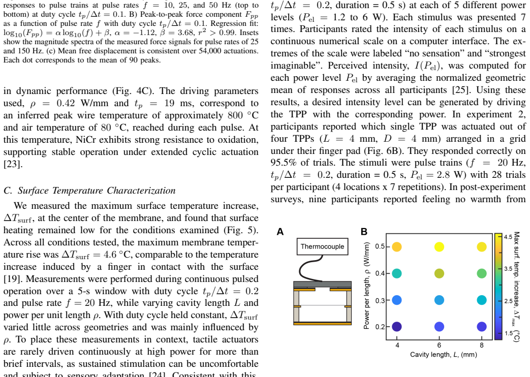
- [Abstract; §III.A; Fig. 4B] The abstract's 'millisecond response times' and 'up to 300 Hz range' are not supported by the reported data. In Fig. 3A, force and displacement reach their peaks only at the end of a 75 ms pulse, and the cooling time constant is τ=110 ms. No rise-time, latency, or bandwidth definition is given, so the '5–100 ms' statement in §II is ambiguous. The cyclic characterization extends only to 200 Hz (Fig. 4B), where Fpp is 7 mN. Please define and report a response-time metric (e.g., 10–90% rise time) and either provide data above 200 Hz or revise the claims.
minor comments (5)
- [Appendix C / Fig. 3E] The failure boundary is a parametric fit to the same failure data (Eq. 2), not an independent prediction. It should be labeled as a fit and, ideally, validated on held-out configurations.
- [§IV / Fig. 6] Perceptual results are reported with R² values only; N=10 with no confidence intervals or inferential tests. Please report per-participant variability and confidence intervals for the 95.5% localization rate and the intensity slope.
- [Fig. 4C] Only mean displacement is plotted over 54,000 cycles; adding variability (e.g., SD or CI) would strengthen the durability claim.
- [Appendix B] Wire temperature is based on 'linearly interpolating tabulated resistivity–temperature data'; NiCr resistivity vs. temperature is not linear over 20–1100 °C. Please specify the interpolation method, table source, and uncertainty.
- [Abstract / §II] The phrases 'millisecond response times' (abstract) and 'response times on the order of 5–100 ms' (§II) are inconsistent; define a single, quantitative response-time metric.
Circularity Check
Force-derived air pressure/temperature are definitionally matched to force; mechanism evidence is partly tautological, but headline outputs are direct measurements.
specific steps
-
self definitional
[Section III.A (Thermomechanical Characterization), equations for P(t) and T_air(t)]
"From the measured force F(t), we computed the gauge air pressure P(t)=F(t)/A ... Air temperature was obtained using the ideal gas law, T_air(t)=T0(F(t)/(P0 A)+1) ... Temperature, pressure, force, and displacement exhibited closely matched temporal profiles"
P and T_air are defined as linear transforms of the measured output force F, with no independent cavity-pressure measurement. The paper's causal narrative—'driving corresponding increases in cavity air temperature and pressure. The resulting membrane force F(t) produced a displacement'—and the 'closely matched temporal profiles' are therefore true by construction. The inferred gas state cannot independently validate the thermopneumatic mechanism; only the raw force/displacement data are non-circular.
full rationale
The headline performance claims (forces >1 N, displacements ~1 mm, 5–100 ms responses) are direct load-cell and laser-triangulation measurements, so the central empirical contribution does not reduce to a fit or to self-citation. The failure boundary in Fig. 3E is explicitly a parametric fit to observed failure points, so it is descriptive rather than a hidden prediction; Eq. (1) is a standard lumped thermal model with tau fitted to the cooling transient. Citations [19] and [20] are the authors' prior thermopneumatic work, but they are used only for qualitative consistency ('consistent with prior observations'), not to force the present result. The one genuine circularity is in the mechanism section: P(t)=F(t)/A and T_air(t)=T0(F(t)/(P0 A)+1) define the inferred gas state from the very force that the gas state is said to cause. The close temporal match between T_air, P, and F is therefore by construction. This weakens the thermopneumatic-mechanism evidence (no independent pressure/temperature measurement is reported) but does not affect the measured actuator output. Hence partial circularity, score 4.
Axiom & Free-Parameter Ledger
free parameters (6)
- tau (thermal time constant) =
110 ms
- a (length-scaled thermal resistance) =
6601 mm K/W
- b (length-scaled thermal mass) =
6.51 uJ/(mm K)
- perceptual intensity slope alpha =
0.2677 W^-1
- perceptual intensity intercept beta =
-0.151
- F_pp frequency slope alpha =
-1.12
axioms (5)
- domain assumption Air in the cavity obeys the ideal gas law with uniform pressure under the membrane: T_air = T0(F/(P0 A) + 1).
- standard math First-order lumped thermal model for the wire (Eq. 1) with constant R_thermal and C.
- domain assumption NiCr resistivity-temperature table and 1400 C melting temperature from the cited datasheet are accurate for the 48 AWG wire.
- domain assumption Measured isometric load-cell force equals pressure force P*A with no membrane tension or edge contribution.
- domain assumption Tactile perception is dominated by the transient high-frequency force component F_pp rather than the slow offset F_0.
read the original abstract
We present thermopneumatic pixels (TPPs) -- low-profile pixels and arrays that generate dynamic tactile feedback. These devices are thin, fast, reconfigurable, and output localized transient displacements at each pixel. Their parsimonious design -- a layered architecture without internal moving parts -- and low-voltage ($\lesssim$10 V) operation may facilitate practical integration in a wide variety of interfaces. Each TPP converts brief electrical pulses into transient air pressure increases in an internal cavity, yielding out-of-plane forces and displacements for tactile feedback. We demonstrate TPPs that output displacements of 1 mm and forces exceeding 1 N, with millisecond response times, in packages that are less than 3 mm thick. Force and displacement increase with pixel surface area, facilitating tailorability. The pixels can also generate oscillating feedback at pulse rates up to 300 Hz range. We report designs for compact arrays of pixels at 4 mm spacing, and simple pulse driving architectures using miniature transistors driven by microcontrollers. We characterize the mechanical, dynamic, and thermal response of TPPs, and their robustness and consistency over tens of thousands of cycles. We report perceptual experiments on spatial localization and intensity as a function of driving power. Together, these results establish thermopneumatic pixels as a compact, adaptable tactile technology that blends performance and practicality.
Figures



Reference graph
Works this paper leans on
-
[1]
Dynamic feedback in wave-mediated surface haptics: A modular platform,
D. Goetz, G. Reardon, M. Linnander, and Y . Visell, “Dynamic feedback in wave-mediated surface haptics: A modular platform,” in2023 IEEE World Haptics Conference (WHC). IEEE, 2023, pp. 107–113. 7
2023
-
[2]
Skinsource: A data-driven toolbox for predicting touch-elicited vibra- tions in the upper limb,
N. Tummala, G. Reardon, S. Fani, D. Goetz, M. Bianchi, and Y . Visell, “Skinsource: A data-driven toolbox for predicting touch-elicited vibra- tions in the upper limb,” in2024 IEEE Haptics Symposium (HAPTICS), 2024, pp. 53–60
2024
-
[3]
Vibraforge: A scalable prototyping toolkit for creating spatialized vibrotactile feedback systems,
B. Huang, S. Ren, Y . Luo, Q. Cheng, H. Cai, Y . Sang, M. Sousa, P. H. Dietz, and D. Wigdor, “Vibraforge: A scalable prototyping toolkit for creating spatialized vibrotactile feedback systems,” inProceedings of the 2025 CHI Conference on Human Factors in Computing Systems, ser. CHI ’25. New York, NY , USA: Association for Computing Machinery, 2025
2025
-
[4]
Open-source hardware and software platform for vibrotactile motion guidance,
N. Rokhmanova, J. Martus, R. Faulkner, J. Fiene, and K. J. Kuchen- becker, “Open-source hardware and software platform for vibrotactile motion guidance,”Device, p. 100966, Oct. 2025
2025
-
[5]
Jones and S
L. Jones and S. Lederman,Human hand function. Oxford University Press, 2006
2006
-
[6]
Identification of the optimum resolution specification for a haptic graphic display,
D. Copeland and J. Finlay, “Identification of the optimum resolution specification for a haptic graphic display,”Interacting with Computers, vol. 22, no. 2, pp. 98–106, 2010
2010
-
[7]
Vibrotactile masking and the persistence of tactual features,
J. C. Craig and P. M. Evans, “Vibrotactile masking and the persistence of tactual features,”Perception and psychophysics, vol. 42, no. 4, pp. 309–317, 1987
1987
-
[8]
Pulse-driven magnetostatic micro-actuator array based on ultrasoft elastomeric mem- branes for active surface applications,
J. Streque, A. Talbi, P. Pernod, and V . Preobrazhensky, “Pulse-driven magnetostatic micro-actuator array based on ultrasoft elastomeric mem- branes for active surface applications,”Journal of Micromechanics and Microengineering, vol. 22, no. 9, p. 095020, aug 2012
2012
-
[9]
Hydraulically amplified electrostatic taxels (haxels) for full body haptics,
E. Leroy and H. Shea, “Hydraulically amplified electrostatic taxels (haxels) for full body haptics,”Advanced Materials Technologies, vol. 8, no. 16, p. 2300242, 2023
2023
-
[10]
Fully 3d-printed, stretchable, and conformable haptic interfaces,
G. Grasso, S. Rosset, and H. Shea, “Fully 3d-printed, stretchable, and conformable haptic interfaces,”Advanced Functional Materials, vol. 33, no. 20, p. 2213821, 2023
2023
-
[11]
A pocket-sized ten- channel high voltage power supply for soft electrostatic actuators,
S. K. Mitchell, T. Martin, and C. Keplinger, “A pocket-sized ten- channel high voltage power supply for soft electrostatic actuators,” Advanced Materials Technologies, vol. 7, no. 8, p. 2101469, 2022. [Online]. Available: https://advanced.onlinelibrary.wiley.com/doi/abs/10. 1002/admt.202101469
2022
-
[12]
Emerging material technologies for haptics,
S. Biswas and Y . Visell, “Emerging material technologies for haptics,” Advanced Materials Technologies, vol. 4, no. 4, p. 1900042, 2019
2019
-
[13]
Flat panel haptics: Embedded electroosmotic pumps for scalable shape displays,
C. Shultz and C. Harrison, “Flat panel haptics: Embedded electroosmotic pumps for scalable shape displays,” inProceedings of the 2023 CHI Conference on Human Factors in Computing Systems, ser. CHI ’23. New York, NY , USA: Association for Computing Machinery, 2023
2023
-
[14]
Fluid reality: High-resolution, untethered haptic gloves using electroosmotic pump arrays,
V . Shen, T. Rae-Grant, J. Mullenbach, C. Harrison, and C. Shultz, “Fluid reality: High-resolution, untethered haptic gloves using electroosmotic pump arrays,” inProceedings of the 36th Annual ACM Symposium on User Interface Software and Technology, ser. UIST ’23. New York, NY , USA: Association for Computing Machinery, 2023
2023
-
[15]
C. J. Camargo, H. Campanella, J. E. Marshall, N. Torras, K. Zinoviev, E. M. Terentjev, and J. Esteve, “Batch fabrication of optical actuators using nanotube–elastomer composites towards refreshable braille displays,”Journal of Micromechanics and Microengineering, vol. 22, no. 7, p. 075009, jun 2012. [Online]. Available: https: //dx.doi.org/10.1088/0960-13...
-
[16]
Laser pouch motors: Selective and wireless activation of soft actuators by laser-powered liquid-to-gas phase change,
T. Hiraki, K. Nakahara, K. Narumi, R. Niiyama, N. Kida, N. Takamura, H. Okamoto, and Y . Kawahara, “Laser pouch motors: Selective and wireless activation of soft actuators by laser-powered liquid-to-gas phase change,”IEEE Robotics and Automation Letters, vol. 5, no. 3, pp. 4180– 4187, 2020
2020
-
[17]
Ultrathin conformable electronic tattoo for tactile sensations,
A. Mazzotta and V . Mattoli, “Ultrathin conformable electronic tattoo for tactile sensations,”Advanced Electronic Materials, vol. 9, no. 9, p. 2201327, 2023
2023
-
[18]
Low-voltage wearable tactile display with thermo-pneumatic actuation,
A. Mazzotta, S. Taccola, I. Cesiniet al., “Low-voltage wearable tactile display with thermo-pneumatic actuation,”npj Flexible Electronics, vol. 9, no. 70, 2025. [Online]. Available: https://doi.org/10.1038/ s41528-025-00426-3
2025
-
[19]
Tactile displays driven by projected light,
M. Linnander, D. Goetz, G. Reardon, V . Kumar, E. Hawkes, and Y . Visell, “Tactile displays driven by projected light,”Science Robotics, vol. 10, no. 107, p. eadv1383, 2025. [Online]. Available: https://www.science.org/doi/abs/10.1126/scirobotics.adv1383
-
[20]
Haptic light-emitting diodes: Miniature, luminous tactile actuators,
M. Linnander and Y . Visell, “Haptic light-emitting diodes: Miniature, luminous tactile actuators,”arXiv preprint arXiv:2601.11043, 2026. [Online]. Available: https://arxiv.org/abs/2601.11043
Pith/arXiv arXiv 2026
-
[21]
80/20 ni cr resistance wire: Technical datasheet aws 180 rev.1,
Alloy Wire International Ltd., “80/20 ni cr resistance wire: Technical datasheet aws 180 rev.1,” Alloy Wire International Ltd., Brierley Hill, West Midlands, UK, Technical Datasheet AWS 180 Rev.1, 2016, avail- able at: https://www.alloywire.com
2016
-
[22]
Thresholds for the perception of hand- transmitted vibration: dependence on contact area and contact location,
M. Morioka and M. J. Griffin, “Thresholds for the perception of hand- transmitted vibration: dependence on contact area and contact location,” Somatosensory and Motor Research, vol. 22, no. 4, pp. 281–297, 2005
2005
-
[23]
High-temperature stability of nichrome in reactive environments,
J. Zhou, T. R. Ohno, and C. A. Wolden, “High-temperature stability of nichrome in reactive environments,”Journal of V acuum Science and Technology A, vol. 21, no. 3, pp. 756–761, 04 2003. [Online]. Available: https://doi.org/10.1116/1.1570834
-
[24]
Effect of prior stimulation on vibrotactile thresholds,
R. T. Verrillo and G. A. Gescheider, “Effect of prior stimulation on vibrotactile thresholds,”Sensory Processes, vol. 1, no. 4, pp. 292–300, 1977
1977
-
[25]
Application of psychophysical techniques to haptic research,
L. A. Jones and H. Z. Tan, “Application of psychophysical techniques to haptic research,”IEEE Transactions on Haptics, vol. 6, no. 3, pp. 268–284, 2013
2013
-
[26]
Problems and methods of psychophysics
S. S. Stevens, “Problems and methods of psychophysics.”Psychological bulletin, vol. 55, no. 4, p. 177, 1958
1958
discussion (0)
Sign in with ORCID, Apple, or X to comment. Anyone can read and Pith papers without signing in.