Characterizing robotic positioners under the influence of changing gravity vectors for future spectroscopic surveys
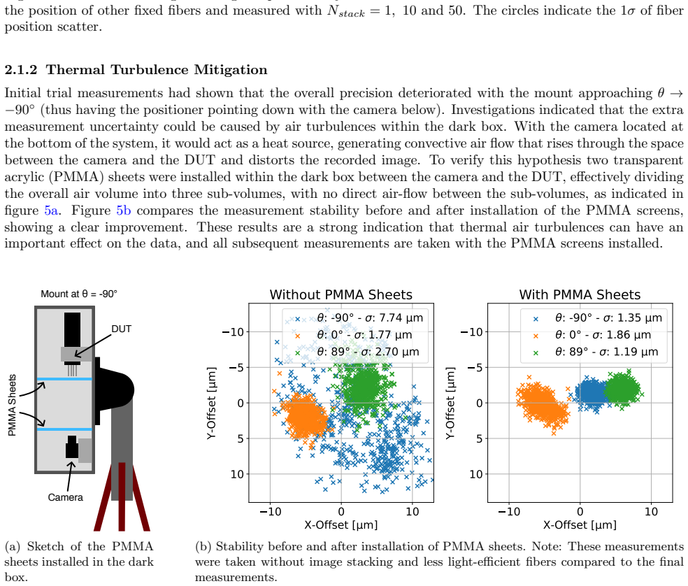
Pith reviewed 2026-06-26 03:36 UTC · model grok-4.3
The pith
An automated test stand orients robotic fiber positioners across gravity directions to verify performance matching telescope conditions.
A machine-rendered reading of the paper's core claim, the machinery that carries it, and where it could break.
Core claim
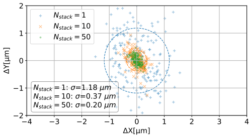
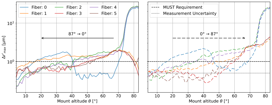
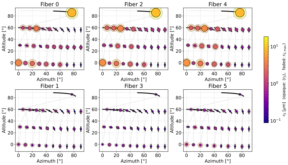
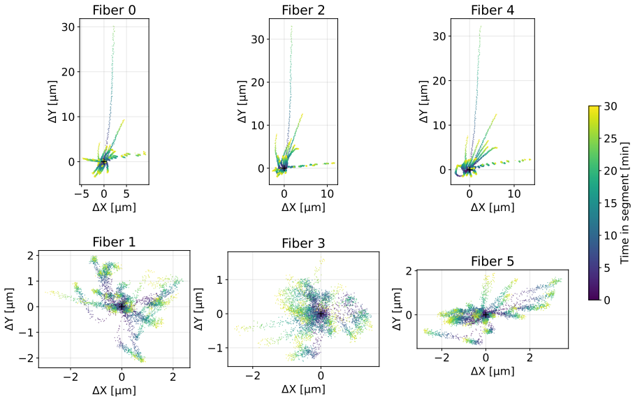
The central claim is that an automated telescope simulator test stand successfully reproduces the gravity vectors of telescope operation, enabling characterization of robotic positioner modules with position stability down to 1 micrometer, focus stability down to 5 micrometers, and tilt variations lower than 0.4 degrees, as shown through initial testing of an Orbray prototype.
What carries the argument
The automated telescope simulator test stand, which rotates the positioner assembly to multiple orientations while applying image-based metrology and calibration for enclosure effects.
If this is right
- Prototypes for multiplexed focal planes can undergo quality assurance under realistic gravity conditions before full assembly.
- Positioner designs can be iterated based on measured gravity-dependent errors in position, focus, and tilt.
- Survey planning can incorporate verified mechanical performance data for fiber placement accuracy.
Where Pith is reading between the lines
- The approach could scale to testing complete focal plane assemblies rather than single modules.
- Calibration routines developed here might transfer to on-telescope alignment procedures.
- Long-term monitoring on the stand could identify time-dependent drifts not visible in short tests.
Load-bearing premise
The stand's gravity reproduction, metrology system, and corrections for turbulence and deformation add no systematic errors larger than the 1 micrometer, 5 micrometer, and 0.4 degree targets when compared to real telescope use.
What would settle it
Direct measurement of a positioner's stability on an actual telescope versus the same module on the test stand, revealing differences exceeding the stated targets.
Figures
read the original abstract
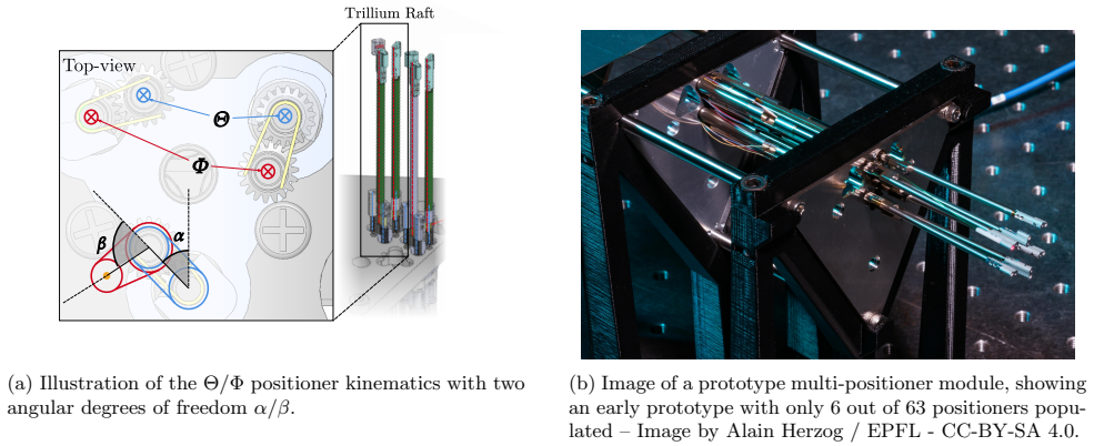
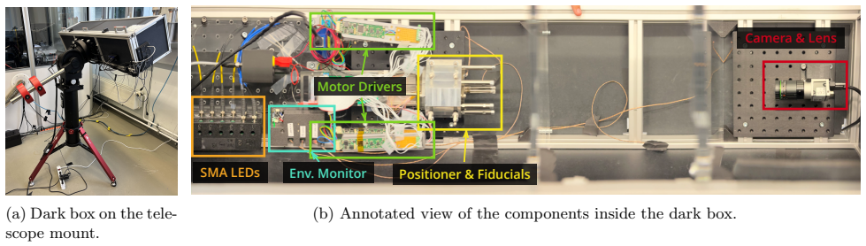
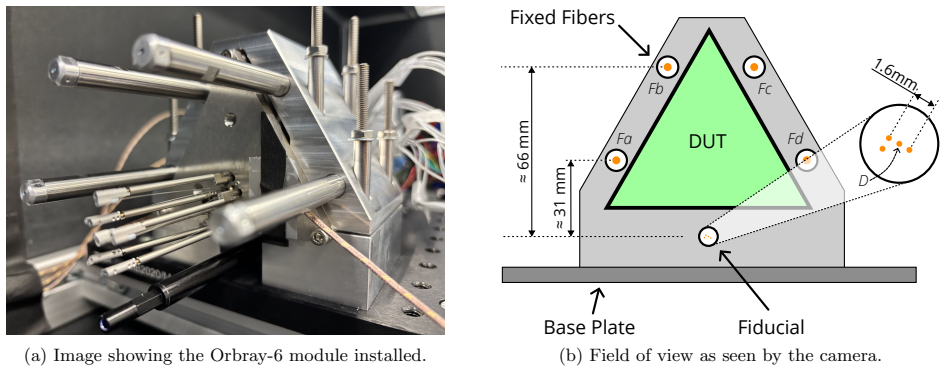
Future (Stage V) spectroscopic surveys intend to accurately map billions of galaxies. To accomplish this goal, these surveys will employ highly multiplexed focal planes composed of robotic fiber positioners to accurately place individual optical fibers on targets of interest. The ambitious science objectives place stringent requirements on the mechanical performance of these positioners. Experience from previous surveys has shown that testing positioners under conditions closely resembling those on the telescope is of utmost importance during the prototyping and quality assurance phases of construction. We present an automated telescope simulator test stand that characterizes the performance of these positioners at different orientations, reproducing the changing gravity vectors encountered during telescope operations. The test stand aims to verify position stability down to 1 um, focus stability down to 5 um, as well as tilt variations lower than 0.4 deg. We discuss the design of our setup, along with early characterization of image quality due to turbulence and the compensation of the enclosure deformation via calibration using fixed spots. Finally, we present initial results of positioning stability tests using a prototype module built by Orbray Co., Ltd. This test setup fulfills an important need for integrated testing of advanced focal plane prototypes under conditions similar to on-telescope conditions.
Editorial analysis
A structured set of objections, weighed in public.
Referee Report
Summary. The paper describes the design of an automated telescope simulator test stand for characterizing robotic fiber positioners under varying gravity vectors, including turbulence characterization, fixed-spot calibration to compensate for enclosure deformation, and initial positioning stability results from an Orbray prototype module. The setup targets position stability of 1 μm, focus stability of 5 μm, and tilt variations below 0.4 deg to support prototyping for future Stage V spectroscopic surveys.
Significance. If the metrology and corrections are shown to keep systematics below the targets, the test stand would address a practical need for integrated, on-telescope-like testing of focal-plane prototypes. The explicit discussion of turbulence effects and deformation compensation via calibration is a constructive element of the experimental design.
major comments (1)
- [Abstract and initial results section] Abstract and the section on initial results: the manuscript states the stability targets and mentions early positioning stability tests, but supplies no quantitative measurements, achieved values, or error budgets demonstrating that the 1 μm / 5 μm / 0.4 deg specifications are met or that residual systematics from turbulence and enclosure deformation remain below these thresholds.
minor comments (2)
- [Methods / calibration subsection] Clarify the exact image-processing pipeline used for the fixed-spot calibration and how residual enclosure deformation is quantified after correction.
- [Turbulence characterization] Add a table or plot summarizing the measured turbulence contribution to image quality as a function of orientation.
Simulated Author's Rebuttal
We thank the referee for their constructive review and recommendation. We address the single major comment below.
read point-by-point responses
-
Referee: [Abstract and initial results section] Abstract and the section on initial results: the manuscript states the stability targets and mentions early positioning stability tests, but supplies no quantitative measurements, achieved values, or error budgets demonstrating that the 1 μm / 5 μm / 0.4 deg specifications are met or that residual systematics from turbulence and enclosure deformation remain below these thresholds.
Authors: We agree that the initial results section does not currently include the specific quantitative measurements, achieved values, or error budgets needed to demonstrate performance relative to the 1 μm / 5 μm / 0.4 deg targets or to quantify residual systematics. In the revised manuscript we will expand the initial results section to report the measured position, focus, and tilt stabilities from the Orbray prototype tests together with the corresponding error budgets and an assessment of turbulence and enclosure-deformation residuals. revision: yes
Circularity Check
No significant circularity; experimental apparatus description only
full rationale
The manuscript is a hardware and metrology paper describing the design, turbulence characterization, fixed-spot calibration, and initial positioning results of an automated telescope simulator test stand. No derivations, equations, fitted parameters, predictions, or uniqueness theorems are present. All performance claims (1 μm position stability, 5 μm focus stability, <0.4 deg tilt) are stated as design targets and measured outcomes rather than outputs derived from inputs by construction. No self-citations are load-bearing for any central claim. The work is therefore self-contained against external benchmarks with no reduction of results to their own inputs.
Axiom & Free-Parameter Ledger
axioms (1)
- standard math Standard assumptions of rigid-body mechanics and optical imaging under controlled laboratory conditions apply to the test stand.
Reference graph
Works this paper leans on
-
[1]
Vallisneriet al.(NANOGrav), (2020), 10.3847/1538- 4357/ab7b67, arXiv:2001.00595 [astro-ph.HE]
Silber, J. H., Fagrelius, P., Fanning, K., Schubnell, M., Aguilar, J. N., et al., “The Robotic Multiobject Focal Plane System of the Dark Energy Spectroscopic Instrument (DESI),”165(1), 9 (2023). doi:10.3847/1538- 3881/ac9ab1
-
[2]
DESI Completes Planned 3D Map of the Universe and Continues Exploring
Biron, L., “DESI Completes Planned 3D Map of the Universe and Continues Exploring.” (2026). https://newscenter.lbl.gov/2026/04/15/desi-completes-planned-3d-map-of-the-universe-and-continues- exploring/
2026
-
[3]
Alam, S., “Completed SDSS-IV extended Baryon Oscillation Spectroscopic Survey: Cosmological impli- cations from two decades of spectroscopic surveys at the Apache Point Observatory,”103(8) (2021). doi:10.1103/PhysRevD.103.083533. 14
-
[5]
DESI Collaboration, Abdul Karim, M., Aguilar, J., Ahlen, S., Alam, S., et al., “DESI DR2 results. II. Measurements of baryon acoustic oscillations and cosmological constraints,”112(8), 083515 (2025). doi:10.1103/tr6y-kpc6
-
[6]
Adame, A., Aguilar, J., Ahlen, S., Alam, S., Alexander, D., et al., “DESI 2024 VII: Cosmological con- straints from the full-shape modeling of clustering measurements,”2025(07), 028 (2025). doi:10.1088/1475- 7516/2025/07/028
-
[7]
2020, title Planck 2018 results
Aghanim, N., Akrami, Y., Ashdown, M., Aumont, J., Baccigalupi, C., et al., “Planck 2018 results - VI. Cosmological parameters,”641, A6 (2020). doi:10.1051/0004-6361/201833910
-
[8]
The Astrophysical Journal , author =
Riess, A. G., Yuan, W., Macri, L. M., Scolnic, D., Brout, D., et al., “A Comprehensive Measurement of the Local Value of the Hubble Constant with 1 km s-1 Mpc-1 Uncertainty from the Hubble Space Telescope and the SH0ES Team,”934(1), L7 (2022). doi:10.3847/2041-8213/ac5c5b
-
[9]
Besuner, R., Dey, A., Drlica-Wagner, A., Ebina, H., Moroni, G. F., et al., “The Spectroscopic Stage-5 Experiment.” (2025). doi:10.48550/arXiv.2503.07923
-
[10]
Zhao, C., Huang, S., He, M., Montero-Camacho, P., Liu, Y., et al., “MUltiplexed Survey Telescope (MUST) Science White Paper I: Overview of Large-Scale Structure Cosmology in the Era of Stage-V Spectroscopic Surveys.” (2026). doi:10.48550/arXiv.2411.07970
work page internal anchor Pith review Pith/arXiv arXiv doi:10.48550/arxiv.2411.07970 2026
-
[11]
d’ Assignies D, W., Zhao, C., Yu, J., and Kneib, J.-P., “Cosmological Fisher forecasts for next-generation spectroscopic surveys,”521(3), 3648–3662 (2023). doi:10.1093/mnras/stad611
-
[12]
Bacon, R., Maineiri, V., Randich, S., Cimatti, A., Kneib, J.-P., et al., “WST – Widefield Spectroscopic Telescope: Motivation, science drivers and top-level requirements for a new dedicated facility.” (2024). doi:10.48550/arXiv.2405.12518
-
[13]
The wide-field spectroscopic telescope (WST) science white paper,
Mainieri, V., Anderson, R. I., Brinchmann, J., Cimatti, A., Ellis, R. S., et al., “The Wide-field Spectroscopic Telescope (WST) Science White Paper.” (2024). doi:10.48550/arXiv.2403.05398
-
[14]
and Galal, Malak and Schlegel, David and Kneib, Jean-Paul , editor =
Rombach, M., Xu, X., Araujo, R., Thurneysen, M., Caseiro, S., et al., “Investigations on assembly and cov- erage for modular focal planes of multiplexed telescopes,” in [Ground-Based and Airborne Instrumentation for Astronomy X],13096, 3396, SPIE (2024). doi:10.1117/12.3018315
-
[15]
Towards the Characterization of Next Generation Robotic Positioners for 3D Mapping of the Universe
Yamani, B., “Towards the Characterization of Next Generation Robotic Positioners for 3D Mapping of the Universe.” (2026). doi:10.5167/uzh-434415
-
[16]
MUST - Fiber Positioner Module Specifications - v2.3.1
Wei, J., Chapuis, D., and Araujo, R., “MUST - Fiber Positioner Module Specifications - v2.3.1.” (2026)
2026
-
[17]
Precision Positioning of Microrobots for Multi-Object Spectrographs
Kronig, L. G., “Precision Positioning of Microrobots for Multi-Object Spectrographs.” (2020). doi:10.5075/epfl-thesis-7774
-
[18]
Prototyping of 6.2-mm-Pitch Fiber Positioner Modules for Stage-V Telescope Instrumentation
Galal, M., Rombach, M., Wei, J., Ara´ ujo, R., Chapuis, D., et al., “Prototyping of 6.2-mm-Pitch Fiber Positioner Modules for Stage-V Telescope Instrumentation.” (2025). doi:10.48550/arXiv.2508.19711
work page internal anchor Pith review Pith/arXiv arXiv doi:10.48550/arxiv.2508.19711 2025
-
[19]
Precision measurements of the axial drift in fiber positioners for spectroscopic surveys using defocus blur [In Preparation],
Lebrun, L., “Precision measurements of the axial drift in fiber positioners for spectroscopic surveys using defocus blur [In Preparation],” in [Advances in Optical and Mechanical Technologies for Telescopes and Instrumentation VII], SPIE (2026)
2026
-
[20]
The DESI Fiber View Camera System,
Baltay, C., Rabinowitz, D., Besuner, R., Casetti, D., Emmet, W., et al., “The DESI Fiber View Camera System,”131(1000), 065001 (2019). doi:10.1088/1538-3873/ab15c2
-
[21]
Cram´ er–Rao lower bounds on the performance of charge-coupled-device optical position estimators,
Winick, K. A., “Cram´ er–Rao lower bounds on the performance of charge-coupled-device optical position estimators,” (1986). doi:10.1364/JOSAA.3.001809
-
[22]
Silber, J. H., Schlegel, D. J., Araujo, R., Baltay, C., Besuner, R. W., et al., “25,000 optical fiber positioning robots for next-generation cosmology.” (2022). doi:10.48550/arXiv.2212.07908
-
[23]
Silber, J. H., “Design of Trillium II Prototype Fiber Robots.” (2022). doi:10.5281/zenodo.6354859. 15
discussion (0)
Sign in with ORCID, Apple, or X to comment. Anyone can read and Pith papers without signing in.