REVIEW 4 major objections 6 minor 43 references
Unified Simulation and Test Platform for Control Systems of Unmanned Vehicles
T0 review · 4 major / 6 minor · reviewed 2026-08-14 · deepseek-v4-flash
Pith's one-line read A unified simulation platform tests real drone autopilots with credibility above 90 percent.
desk verdict Solid systems integration paper with a plausible multicopter validation and good reproducibility, but the >90% credibility claim is in-sample and the unified-vehicle scope is not quantified. read the letter →
The pith
A machine-rendered reading of the paper's core claim, the machinery that carries it, and where it could break.
The reading
What carries the argument
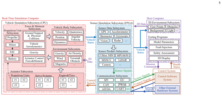
The load-bearing mechanism is the three-way separation of the simulation world around the control system: the vehicle simulation subsystem (body, environment, actuator, force and moment), the 3D environment subsystem, and the sensor simulation subsystem that turns vehicle states into binary electrical signals. The sensor simulation runs on an FPGA because bus protocols such as SPI need nanosecond-level update rates that CPU-based simulators cannot reliably reach, and this is what lets a real autopilot operate as though its sensors were present. Model-based design with modular visual programming and automatic code generation standardizes the development process, so the credibility of the software rests on the generation tools rather than on hand-written code.
What would settle it
Identify model parameters from one set of tests, then run the HIL platform on a separate, never-seen flight and compute the credibility index against independent experimental data; if the index falls below the paper's 60 percent threshold, the claimed above-90 percent credibility does not generalize.
Extended reading notes
Core claim
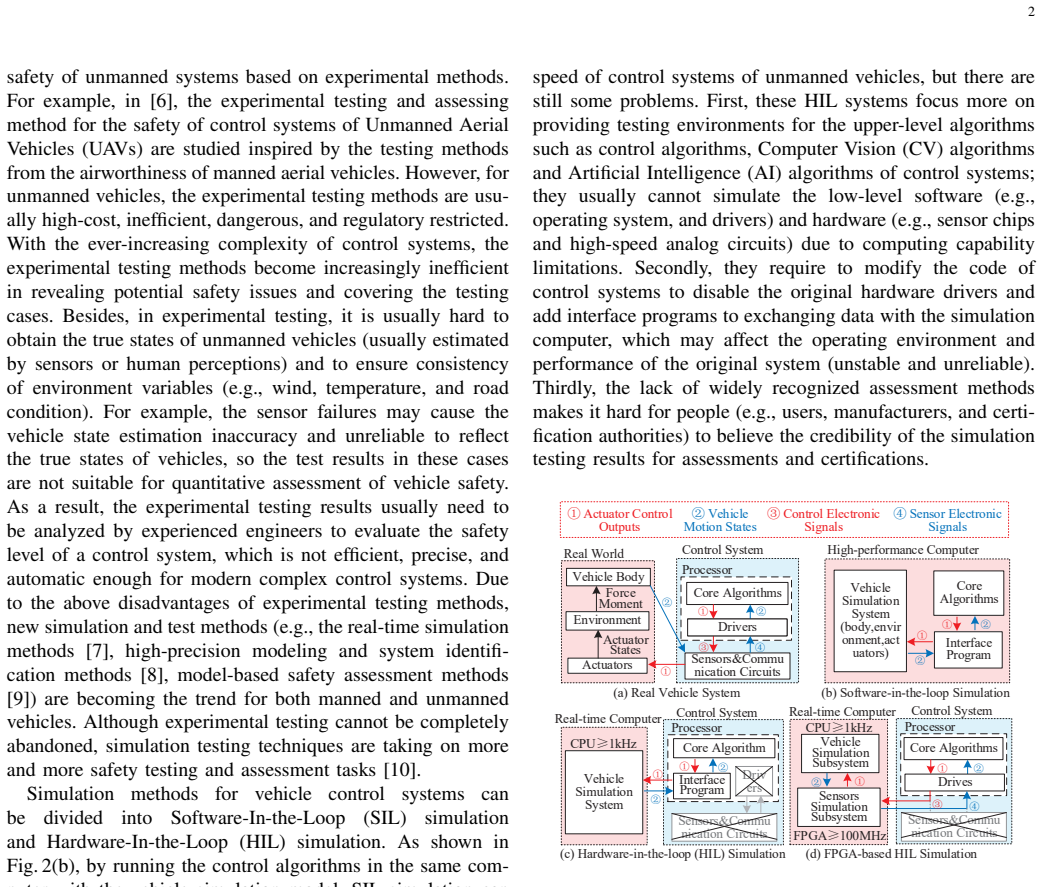
The central claim is that the proposed platform produces simulation testing results whose accuracy is close enough to real experiments to be trusted for development and safety assessment. The platform separates the world outside the control system into three simulated parts: a CPU-based real-time computer runs the vehicle simulation (body, environment, actuators, forces and moments) at update rates up to 5 kHz; an FPGA-based system runs the sensor simulation, including bus-level electronic signals such as SPI and I2C, at up to 100 MHz; and a host computer runs a 3D visual environment. The autopilot under test is treated as a black box: its own sensors are blocked, its pins are reconnected to the FPGA, and it receives simulated chip-level signals, so the same hardware runs in both simulation and experiment. The multicopter model is validated by comparing accelerometer and gyroscope noise and vibration, motor and propeller response, and pitch-channel frequency responses against test-bench and flight data, and the authors' previous credibility assessment method yields a matching index larger than 90 percent, with 60 percent the minimum acceptable and 100 percent a perfect match.
Load-bearing premise
The claim stands on the assumption that the multicopter model's parameters, identified from the same test bench and flight experiments used for comparison, combined with the authors' own credibility index, truthfully reflect how well the platform would match real vehicles of other types.
Editorial extensions
If this is right
- If the reported credibility transfers, manufacturers could run large numbers of rare-fault and failure-injection tests indoors, automatically, without risking vehicles.
- Because the control system is a black box, the same platform could test autopilots from different vendors without access to their source code.
- The modular vehicle model means that replacing the propeller module with a tire module or a wing module should extend the same platform to cars and fixed-wing aircraft.
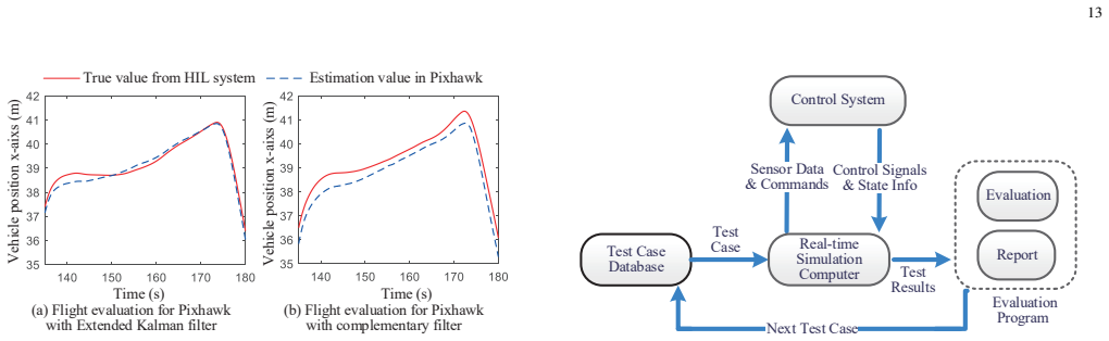
- The platform supplies true vehicle states, so estimation filters and control algorithms can be compared against ground truth without expensive differential GPS or motion-capture systems.
- The proposed certification framework suggests a path where certified component models form a standard product-model database, shortening approval cycles for new vehicles.
Reading between the lines
- The 90 percent credibility figure is computed with the authors' own companion assessment method, so an independent observer applying the same comparison to an unseen vehicle model would test whether the number generalizes.
- Because the platform exposes true vehicle states and is repeatable, it could host automated search-based or adversarial safety testing that systematically perturbs flight conditions and faults to find failure cases; the paper's automatic testing framework points toward, but does not develop, that use.
- The same modular structure could be extended to multi-vehicle scenarios and to vehicles with different actuator physics, such as cars and fixed-wing aircraft, but the quantitative credibility evidence in the paper is limited to the multicopter.
- If model parameters for each new vehicle type are identified on their own test benches rather than borrowed from the multicopter, the claimed extensibility becomes directly testable.
Signed reviews
Editorial analysis
A structured set of objections, weighed in public.
Referee Report
Summary. The paper describes a unified simulation and test platform for unmanned vehicle control systems. It combines a modular vehicle modeling framework, a model-based design development process, and an FPGA-based hardware-in-the-loop (HIL) setup that connects a real Pixhawk autopilot to sensor-level electrical signals. The platform is demonstrated on an F450 quadcopter: component-level comparisons (IMU noise/vibration, motor response, propeller thrust, pitch-channel Bode plots) and level-flight responses are shown against experiments, and the authors report a simulation credibility index larger than 90% from their companion method. Additional applications include rapid prototyping via an online toolbox, estimator comparison, autonomous mission testing, and automatic safety testing with fault injection.
Significance. If the credibility claim were properly supported, the platform would be a useful contribution: it enables black-box testing of unmodified autopilot hardware at the electrical-signal level, which is more faithful than conventional SIL and avoids code modification. Strengths of the paper are the modular system decomposition, the open-source CopterSim code, the released videos, and the concrete F450/Pixhawk test setup. The major limitation is that the central quantitative claim, the >90% credibility index, rests on in-sample validation and is not independently reproducible from the manuscript, so the significance for the claimed unified scope (cars, fixed-wing, fault-injection safety testing) is not yet established.
major comments (4)
- [IV.B.3, Figs. 13 and 14] The model parameters shown in Fig. 14, including C_T, C_M, C_R, omega_b, J_m, T_m, C_d, and C_m, are identified from the same test-bench and flight experiments that are then used for the comparisons in Fig. 13. This makes the agreement in Fig. 13 partly an in-sample restatement of the fit rather than a predictive test. Please add a hold-out validation set, cross-validation, or an uncertainty analysis, and report residuals or confidence intervals for the identified parameters.
- [IV.B.3, credibility index] The claim that the credibility index is 'larger than 90%' is not substantiated in the manuscript: the computation is not reproduced, the per-aspect scores are not given, and no error bars or confidence intervals are reported. Although reference [24] proposes the method, the reader cannot check whether the 90% threshold was applied consistently. Please provide the actual assessment results and a precise definition of the 'credibility index' used here.
- [IV.B.3 and IV.C] The quantitative validation is restricted to a single multicopter (F450) and mostly to component-level or one-axis bench tests. The extension of the platform to cars, fixed-wing aircraft, and automatic safety testing is supported only by qualitative demonstrations, videos, and the statement that the website-estimated model in Fig. 15(b) is 'acceptable.' To support the unified-scope claim, either provide representative quantitative validation for at least one additional vehicle type or state explicitly that the credibility claim applies only to the multicopter case.
- [IV.C.1, Fig. 15] The level-flight comparison in Fig. 15 uses the high-precision model calibrated with the same experimental data shown in Fig. 13, and the agreement with the real quadcopter is described as 'almost coincides' without a quantitative metric. The website-estimated model is judged visually and not scored with the credibility index. Please provide quantitative error metrics (e.g., RMS error, settling time, steady-state error) for both models and state whether the parameters used for Fig. 15(c) were calibrated to the same flight shown in Fig. 15(a).
minor comments (6)
- [Throughout] The term 'UA V' appears with a space as 'UA Vs' and 'UA Vs'; please use 'UAV' consistently.
- [II, Eq. (5)] The notation is garbled: 'bw' should be 'bω', and the superscripts in 'R3' are missing. Please proofread the equation.
- [II.D.2] The text says 'senor product subsystem'; 'senor' should be 'sensor'.
- [IV.B.3] The pitch-channel sweep frequency test is said to use 'the test bench presented in Fig. 12(c)', but Fig. 12(c) shows the bifilar pendulum for moment of inertia; the attitude response bench is in Fig. 12(b).
- [References] Reference [10] cites AIAA 2018-2768, but the text refers to an Infotech@Aerospace 2007 paper; please verify the publication year and paper number.
- [Fig. 13] The panels (a)-(f) are referenced in the text but the caption does not describe each panel; adding a short description of each panel would improve readability.
Circularity Check
Credibility index >90% is computed on an in-sample, self-authored validation; the high-precision model is calibrated with the same experiments used to verify it.
-
fitted input called prediction
[Section IV.B.2 (Experimental Setup) and Section IV.B.3 (Simulation validation); Figs. 12-15]
"Besides, lots of outdoor flight tests are also performed to obtain the aerodynamic coefficients of the tested quadcopter and verify the platform simulation results with actual flight results."
The aerodynamic coefficients (e.g., C_d and C_m in Fig. 14) are obtained from the same outdoor flight tests that are then used as the reference for verification in Fig. 13 and Fig. 15. Section IV.C.1 also calls the best-matching model a 'high-precision model calibrated with experimental data in Fig. 13' before reporting that it 'almost coincides with the real experimental curve.' The agreement between simulation and experiment is therefore a restatement of the calibration data, not an independent prediction; the same in-sample comparison is then scored with the credibility index.
-
self citation load bearing
[Section IV.B.3 (Simulation validation), final paragraph]
"The quantitative simulation credibility assessment method proposed in our previous work [24] is applied in this paper to assess and improve the simulation credibility of the HIL platform, which ensures that a high matching degree (the credibility index in [24]) larger than 90% (where 60% presents the minimum accuracy requirement, and 100% presents a perfect match) is obtained by analyzing the results between the test platform and real experimental system from the quantitative perspective."
The central quantitative evidence for the platform's credibility is a single number, 'larger than 90%', produced by the authors' own companion method [24] (same four authors, arXiv:1907.03981). The computation is not reproduced here, and no independent or hold-out benchmark is used. Because the underlying comparison is the same in-sample fit described above, the >90% figure inherits the calibration dependence instead of providing external confirmation. The claim that the unified platform is credible for cars and fixed-wing aircraft is extrapolated from this multicopter-specific, self-scored result without separate quantitative validation.
full rationale
The paper's engineering contribution — an FPGA-based HIL platform with the same Pixhawk hardware, MBD toolchain, and open-source CopterSim — is real and not circular. The circularity is concentrated in the quantitative validation loop. Section IV.B.2 states that outdoor flight tests are used both to obtain aerodynamic coefficients and to verify the simulation against the actual flight results; Section IV.C.1 then describes the best-matching model as 'calibrated with experimental data in Fig. 13' and presents its agreement with the real curve as evidence. Thus the Fig. 13 and Fig. 15 comparisons are partly in-sample. The single credibility number >90% comes from the authors' own companion method [24], not from an external or held-out benchmark, and the non-calibrated 'website estimated model' is only judged 'acceptable' visually and is not scored. The extension to cars and fixed-wing aircraft rests on qualitative demo videos rather than quantitative validation. These issues make the central claim 'simulation testing results are credible' partially circular; however, the hardware-in-the-loop setup, the use of a real autopilot, and the released code provide independent content, so a moderate score is appropriate.
Assumptions & free parameters
free parameters (12)
- Propeller thrust coefficient C_T =
9.286e-6 N/(rad/s)^2
- Propeller moment coefficient C_M =
1.189e-7 N.m/(rad/s)^2
- Motor steady-speed gain C_R =
691.33 rad/s
- Motor steady-speed offset omega_b =
162.59 rad/s
- Motor-propeller inertia J_m =
8.18e-5 kg.m^2
- Motor response time constant T_m =
0.0119 s
- Air drag coefficient C_d =
6.697e-2 N/(m/s)^2
- Air torque coefficient C_m =
9.174e-3 N.m/(rad/s)^2
- Multicopter mass m =
1.4 kg
- Inertia matrix J =
diag(1.704e-2, 1.704e-2, 3.176e-2) kg.m^2
- Sensor noise standard deviations sigma_a and sigma_b =
Not specified numerically
- Sensor calibration parameters T_e, K_e, p_e =
Not specified
assumptions (7)
- domain assumption The vehicle body can be modeled with rigid-body, flat-earth 6-DOF equations.
- domain assumption Actuator systems can be represented as a steady-state function plus a first-order or second-order linear dynamic response around the rated condition.
- domain assumption Total force and moment decompose as a linear superposition of aerodynamic, gravitational, contact, and actuator forces.
- domain assumption Sensor errors follow the bias-plus-Gaussian-noise and calibration models of Eqs. 11 and 12.
- domain assumption Environmental models WGS84, ISA, WMM, and MIL-F-8785C wind components are accurate for the simulated conditions.
- domain assumption The simulation credibility assessment method in the authors' previous work [24] gives a valid measure of credibility, with 60% as the minimum accuracy requirement and 100% as perfect match.
- domain assumption A model validated on one multicopter configuration extends to other vehicle types by changing module parameters.
Cite this review
Pith. "Pith review of Unified Simulation and Test Platform for Control Systems of Unmanned Vehicles." pith.science (2026). https://pith.science/paper/PKWTDQ3O
@misc{pith2026190802704,
  author       = {Pith},
  title        = {Pith review of: Unified Simulation and Test Platform for Control Systems of Unmanned Vehicles},
  year         = {2026},
  howpublished = {\url{https://pith.science/paper/PKWTDQ3O}},
  note         = {Machine review of arXiv:1908.02704}
}
read the original abstract
Control systems on unmanned vehicles are safety-critical systems whose requirements on reliability and safety are ever-increasing. Currently, testing a complex autonomous control system is an expensive and time-consuming process, which requires massive repeated experimental testing during the whole development stage. This paper presents a unified simulation and test platform for vehicle autonomous control systems aiming to significantly improve the development speed and safety level of unmanned vehicles. First, a unified modular modeling framework compatible with different types of vehicles is proposed with methods to ensure modeling credibility. Then, the simulation software system is developed by the model-based design framework, whose modular programming methods and automatic code generation functions ensure the efficiency, credibility, and standardization of the system development process. Finally, an FPGA-based real-time hardware-in-the-loop simulation platform is proposed to ensure the comprehensiveness and credibility of the simulation and test results. In the end, the proposed platform is applied to a multicopter control system. By comparing with experimental results, the accuracy and credibility of the simulation testing results are verified by using the simulation credibility assessment method proposed in our previous work. To verify the practicability of the proposed platform, several successful applications are presented for the multicopter rapid prototyping, estimation algorithm verification, autonomous flight testing, and automatic safety testing with automatic fault injection and result evaluation of unmanned vehicles.
Figures


Figures from the paper (13 more)



Reference graph
Works this paper leans on
-
[24]
Simulation Credibility Assessment Methodology with FPGA-based Hardware-in-the-loop Platform
X. Dai, C. Ke, Q. Quan, and K.-Y . Cai, “Simulation credibility assessment methodology with FPGA-based hardware-in-the-loop platform,” arXiv e-prints , vol. arXiv:1907.03981, pp. 1–8, 2019. [Online]. Available: https://arxiv.org/abs/1907.03981
work page Pith review arXiv 1907
-
[1]
A novel robotic platform for aerial manipulation using quadrotors as rotating thrust generators,
H. N. Nguyen, S. Park, J. Park, and D. Lee, “A novel robotic platform for aerial manipulation using quadrotors as rotating thrust generators,” IEEE Transactions on Robotics , vol. 34, no. 2, pp. 353–369, 2018
work page 2018
-
[2]
Fast, generic, and reliable control and sim- ulation of soft robots using model order reduction,
O. Goury and C. Duriez, “Fast, generic, and reliable control and sim- ulation of soft robots using model order reduction,” IEEE Transactions on Robotics, vol. 34, no. 6, pp. 1565–1576, 2018
work page 2018
-
[3]
H. Lipson and M. Kurman, Driverless: intelligent cars and the road ahead. Mit Press, 2016
work page 2016
-
[4]
Nonlinear visual control of unmanned aerial vehicles in gps-denied environments,
R. Mebarki, V . Lippiello, and B. Siciliano, “Nonlinear visual control of unmanned aerial vehicles in gps-denied environments,” IEEE Transac- tions on Robotics , vol. 31, no. 4, pp. 1004–1017, 2015
work page 2015
-
[5]
Reactive trajectory generation for multiple vehicles in unknown environments with wind disturbances,
K. Cole and A. M. Wickenheiser, “Reactive trajectory generation for multiple vehicles in unknown environments with wind disturbances,” IEEE Transactions on Robotics , vol. 34, no. 5, pp. 1333–1348, 2018
work page 2018
-
[6]
C. M. Belcastro, D. H. Klyde, M. J. Logan, R. L. Newman, and J. V . Foster, “Experimental flight testing for assessing the safety of unmanned aircraft system safety-critical operations,” in 17th AIAA Aviation Technology, Integration, and Operations Conference . AIAA 2017-3274, 2017
work page 2017
-
[7]
An overall study of a real- time simulator and application of RT-LAB using MATLAB simpower- systems,
S. S. Noureen, V . Roy, and S. B. Bayne, “An overall study of a real- time simulator and application of RT-LAB using MATLAB simpower- systems,” in 2017 IEEE Green Energy and Smart Systems Conference , 2018, pp. 1–5
work page 2017
Show all 43 references
-
[8]
System identification methods for aircraft flight control development and validation,
M. B. Tischler, “System identification methods for aircraft flight control development and validation,” in Advances In Aircraft Flight Control , 2018, pp. 35–69
2018
-
[9]
Model-based safety assessment: Review of the discipline and its challenges,
O. Lisagor, T. Kelly, and R. Niu, “Model-based safety assessment: Review of the discipline and its challenges,” ICRMS’2011 - Safety First, Reliability Primary: Proceedings of 2011 9th International Conference on Reliability, Maintainability and Safety , pp. 625–632, 2011
2011
-
[10]
Modeling and hardware-in-the-loop simulation for a small unmanned aerial vehicle,
D. Jung and P. Tsiotras, “Modeling and hardware-in-the-loop simulation for a small unmanned aerial vehicle,” inAIAA Infotech@Aerospace 2007 Conference and Exhibit . AIAA 2018-2768, May. 2007
2007
-
[11]
Airsim: High-fidelity visual and physical simulation for autonomous vehicles,
S. Shah, D. Dey, C. Lovett, and A. Kapoor, “Airsim: High-fidelity visual and physical simulation for autonomous vehicles,” in Field and service robotics, 2018, pp. 621–635
2018
-
[12]
SwarmSim: a frame- work for modeling swarming unmanned aerial vehicles using hardware- in-the-loop,
D. B. Worth, B. G. Woolley, and D. D. Hodson, “SwarmSim: a frame- work for modeling swarming unmanned aerial vehicles using hardware- in-the-loop,”The Journal of Defense Modeling and Simulation, pp. 1–20, 2017
2017
-
[13]
Simulation tools, environments and frameworks for UA V systems performance analysis,
A. I. Hentati, L. Krichen, M. Fourati, and L. C. Fourati, “Simulation tools, environments and frameworks for UA V systems performance analysis,” 2018 14th International Wireless Communications & Mobile Computing Conference (IWCMC) , pp. 1495–1500, 2018
2018
-
[14]
State of the art: hardware in the loop modeling and simulation with its applications in design, development and implementation of system and control software,
P. Sarhadi and S. Yousefpour, “State of the art: hardware in the loop modeling and simulation with its applications in design, development and implementation of system and control software,” International Journal of Dynamics and Control , vol. 3, no. 4, pp. 470–479, 2015
2015
-
[15]
Dynamic evolution of simulated autonomous cars in the open world through tactics,
J. R. Sylnice and G. H. Alf ´erez, “Dynamic evolution of simulated autonomous cars in the open world through tactics,” in Proceedings of the Future Technologies Conference , 2018, pp. 257–268
2018
-
[16]
Autonomous vehicle testing and validation platform: Integrated simulation system with hardware in the loop,
Y . Chen, S. Chen, T. Zhang, S. Zhang, and N. Zheng, “Autonomous vehicle testing and validation platform: Integrated simulation system with hardware in the loop,” in2018 IEEE Intelligent Vehicles Symposium (IV), 2018, pp. 949–956
2018
-
[17]
Bilateral teleoperation of groups of mobile robots with time-varying topology,
A. Franchi, C. Secchi, H. I. Son, H. H. B ¨ulthoff, and P. R. Giordano, “Bilateral teleoperation of groups of mobile robots with time-varying topology,” IEEE Transactions on Robotics , vol. 28, no. 5, pp. 1019– 1033, 2012
2012
-
[18]
A distributed control approach to formation balancing and maneuvering of multiple multirotor UA Vs,
Y . Liu, J. M. Montenbruck, D. Zelazo, M. Odelga, S. Rajappa, H. H. Bulthoff, F. Allgower, and A. Zell, “A distributed control approach to formation balancing and maneuvering of multiple multirotor UA Vs,” IEEE Transactions on Robotics , vol. 34, no. 4, pp. 870–882, 2018
2018
-
[19]
AADS: Augmented autonomous driving simulation using data-driven algorithms,
W. Li, C. W. Pan, R. Zhang, J. P. Ren, Y . X. Ma, J. Fang, F. L. Yan, Q. C. Geng, X. Y . Huang, H. J. Gong, W. W. Xu, G. P. Wang, D. Manocha, and R. G. Yang, “AADS: Augmented autonomous driving simulation using data-driven algorithms,” Science Robotics, vol. 4, no. 28, 2019
2019
-
[20]
Real-time simulation of MMCs using CPU and FPGA,
H. Saad, T. Ould-Bachir, J. Mahseredjian, C. Dufour, S. Dennetiere, and S. Nguefeu, “Real-time simulation of MMCs using CPU and FPGA,” IEEE Transactions on Power Electronics , vol. 30, no. 1, pp. 259–267, 2015
2015
-
[21]
Review of real-time simulator and the steps involved for implementation of a model from MAT- LAB/SIMULINK to real-time,
S. Mikkili, A. K. Panda, and J. Prattipati, “Review of real-time simulator and the steps involved for implementation of a model from MAT- LAB/SIMULINK to real-time,” Journal of The Institution of Engineers (India): Series B , vol. 96, no. 2, pp. 179–196, 2015
2015
-
[22]
Simulation credibility: Advances in verification, validation, and uncertainty quantification,
U. B. Mehta, D. R. Eklund, V . J. Romero, J. A. Pearce, and N. S. Keim, “Simulation credibility: Advances in verification, validation, and uncertainty quantification,” NASA Ames Research Center, Moffett Field, CA United States, Tech. Rep. JANNAF/GL-2016-0001, Nov. 01, 2016
2016
-
[23]
Model-based design - MATLAB & Simulink,
I. MathWorks, “Model-based design - MATLAB & Simulink,” https://www.mathworks.com/solutions/model-based-design.html, Accessed May 24, 2019
2019
-
[25]
Towards an extended model-based definition for the digital twin,
A. M. Miller, R. Alvarez, and N. Hartman, “Towards an extended model-based definition for the digital twin,” Computer-Aided Design and Applications, vol. 15, no. 6, pp. 880–891, 2018
2018
-
[26]
B. L. Stevens and F. L. Lewis, Aircraft Control and Simulation 2nd Edition. Wiley, New Jersey, 2004
2004
-
[27]
Quan, Introduction to Multicopter Design and Control
Q. Quan, Introduction to Multicopter Design and Control . Springer, Singapore, 2017
2017
-
[28]
R. W. Smith, Department of Defense World Geodetic System 1984: its definition and relationships with local geodetic systems . Defense Mapping Agency, 1987
1984
-
[29]
The international standard atmosphere (ISA),
M. Cavcar, “The international standard atmosphere (ISA),” Anadolu University, Turkey, vol. 30, p. 9, 2000
2000
-
[30]
Chulliat, S
A. Chulliat, S. Macmillan, P. Alken, C. Beggan, M. Nair, B. Hamilton, A. Woods, V . Ridley, S. Maus, and A. Thomson, The US/UK world magnetic model for 2015-2020 . BGS and NOAA, 2015
2015
-
[31]
Background information and user guide for MIL-F-8785C, military specification-flying qualities of piloted airplanes,
D. J. Moorhouse and R. J. Woodcock, “Background information and user guide for MIL-F-8785C, military specification-flying qualities of piloted airplanes,” U.S. Air Force Wright Aeronautical Labs, Wright-Patterson AFB, OH, Tech. Rep. AFW AL-TR-81-3109, July. 1982
1982
-
[32]
R. K. Remple and M. B. Tischler, Aircraft and rotorcraft system identification: engineering methods with flight-test examples. American Institute of Aeronautics and Astronautics, 2006
2006
-
[33]
G. Cai, B. M. Chen, and T. H. Lee, Unmanned rotorcraft systems . Springer Science & Business Media, 2011
2011
-
[34]
Rajamani, Vehicle dynamics and control, Second Edition
R. Rajamani, Vehicle dynamics and control, Second Edition . Springer Science & Business Media, 2011
2011
-
[35]
Simulation tools, environments and frameworks for UA V systems performance analysis,
A. I. Hentati, L. Krichen, M. Fourati, and L. C. Fourati, “Simulation tools, environments and frameworks for UA V systems performance analysis,” 2018 14th International Wireless Communications and Mobile Computing Conference, IWCMC 2018 , pp. 1495–1500, 2018
2018
-
[36]
R. W. Beard and T. W. McLain, Small unmanned aircraft: Theory and practice. Princeton university press, 2012
2012
-
[37]
Simulation of camera features,
M. Ku ˇciˇs and P. Zem ˇc´ık, “Simulation of camera features,” Proceedings of the 16th Central European Seminar on Computer Graphics , pp. 117– 123, 2012
2012
-
[38]
An introduction to I2C and SPI protocols,
F. Leens, “An introduction to I2C and SPI protocols,” IEEE Instrumen- tation & Measurement Magazine , vol. 12, no. 1, pp. 8–13, 2009
2009
-
[39]
Analysis and modeling of inertial sensors using allan variance,
N. El-Sheimy, H. Hou, and X. Niu, “Analysis and modeling of inertial sensors using allan variance,”IEEE Transactions on instrumentation and measurement, vol. 57, no. 1, pp. 140–149, 2008
2008
-
[40]
NASA HL-20 lifting body airframe modeled with Simulink and the aerospace blockset,
S. Gage, “NASA HL-20 lifting body airframe modeled with Simulink and the aerospace blockset,” https://www.mathworks.com/help/aeroblks/ nasa-hl-20-lifting-body-airframe.html, Accessed May 24, 2019
2019
-
[41]
A practical performance evaluation method for electric multicopters,
D. Shi, X. Dai, X. Zhang, and Q. Quan, “A practical performance evaluation method for electric multicopters,” IEEE/ASME Transactions on Mechatronics, vol. 22, no. 3, pp. 1337–1348, 2017
2017
-
[42]
An analytical design optimization method for electric propulsion systems of multicopter UA Vs with desired hovering endurance,
X. Dai, Q. Quan, J. Ren, and K.-Y . Cai, “An analytical design optimization method for electric propulsion systems of multicopter UA Vs with desired hovering endurance,” IEEE/ASME Transactions on Mechatronics, vol. 24, no. 1, pp. 228–239, 2019
2019
-
[43]
Efficiency optimization and component selection for propulsion systems of electric multicopters,
X. Dai, Q. Quan, J. Ren, and C. Kai-Yuan, “Efficiency optimization and component selection for propulsion systems of electric multicopters,” IEEE Transactions on Industrial Electronics , vol. 66, no. 10, pp. 7800– 7809, 2019
2019
Reviewed August 14, 2026 · model on record in the stance chip above.
Discussion (0). Continue with ORCID to comment.