REVIEW 5 minor 1 cited by
Single-atom electron paramagnetic resonance in a scanning tunneling microscope driven by a radiofrequency antenna at 4 K
T0 review · 0 major / 5 minor · reviewed 2026-08-14 · deepseek-v4-flash
Pith's one-line read A simple RF antenna next to the STM tip drives single-atom EPR at 4.5 K with near-unity coupling efficiency.
desk verdict Solid EPR-STM advance at 4 K with a soft coupling-efficiency claim that should be tempered. read the letter →
The pith
A machine-rendered reading of the paper's core claim, the machinery that carries it, and where it could break.
The reading
What carries the argument
The load-bearing object is the radiofrequency antenna and the equivalent circuit of its coupling to the junction: an antenna-to-sample capacitance $C_S$, an antenna-to-tip capacitance $C_T$, and a tunnel junction represented by a resistance $R_J$ in parallel with a capacitance $C_J$. The model gives $U_{\rm RF} = U_A \left( \frac{C_T+C_J}{C_T} + \frac{1}{2\pi i f R_J C_T} \right)^{-1}$, which at GHz frequencies reduces to $U_{\rm RF} \approx U_A$ whenever $C_T \gg C_J$. This is what makes the coupling efficiency of order unity: the antenna voltage appears almost directly across the junction, independent of the detailed cable losses. The model also lets the authors estimate the RF magnetic field at the junction and argue that it is far too weak to drive the observed EPR, pointing instead to an electric-field-based excitation mechanism.
What would settle it
Place a calibrated power sensor at the antenna feed point inside the cryostat and compare the measured power with the $13 \pm 3$ dB cable-loss estimate, or replace the tip with a known 50-ohm test structure and check whether the capacitive divider reproduces the inferred $U_{\rm RF}$; either measurement would settle the near-unity coupling claim.
Extended reading notes
Core claim
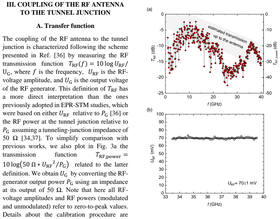
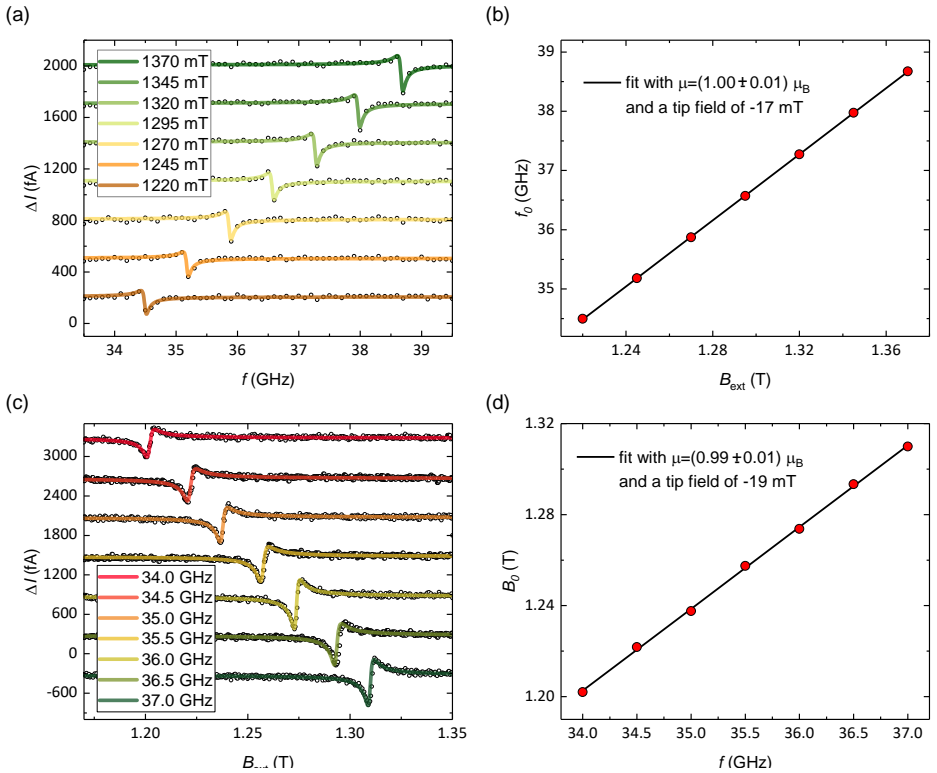
The central claim is that a 5-mm unshielded antenna held about 5 mm from the STM tip, at roughly 30° to it, capacitively injects the RF voltage into the tunnel junction with a transfer ratio close to one. The authors model the antenna–tip–sample system as a capacitive divider in which the antenna–tip capacitance dominates the tunnel-junction capacitance, so the RF voltage across the junction approximately equals the antenna voltage. From a measured transmission function $T_{\rm RF}$ between 1 and 40 GHz and an independent estimate of cable losses of $13 \pm 3$ dB at 40 GHz, they infer that the antenna-to-junction step loses almost nothing. On hydrogenated Ti atoms on two monolayers of MgO on Ag(100), this produces clear EPR resonances at 4.5–5 K, with Fano line shapes, linewidths near 100 MHz, and a fitted magnetic moment of $1.00 \pm 0.01\,\mu_{\rm B}$.
Load-bearing premise
The claim that the antenna-to-junction coupling is near unity rests on subtracting an estimated $13 \pm 3$ dB of cable and connector loss from the measured total transmission; if the true loss is larger than estimated, the inferred junction voltage and coupling efficiency shrink correspondingly, and the main technological advantage weakens.
Editorial extensions
If this is right
- EPR-STM can be performed in standard 4 K cryostats without feeding RF through the tip wiring, removing a major technical barrier.
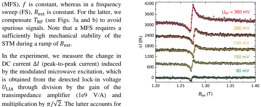
- Magnetic-field sweeps yield the same magnetic moment as frequency sweeps while avoiding the hour-long RF calibration, so spectra can be acquired faster and at higher power.
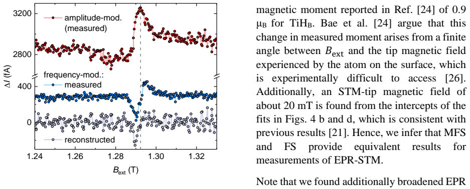
- Frequency modulation of the RF excitation gives a derivative-like EPR line containing the same information as amplitude modulation but with less sensitivity to rectification background, helping signal-to-noise ratio and imaging.
- Delivered RF amplitudes up to about 360 mV above 30 GHz should allow Rabi rates to approach spin-decoherence rates, a step toward pulsed EPR and coherent spin control of single atoms.
- The persistence of linewidths near 100 MHz at 4–5 K indicates energy resolution near $1\,\mu$eV, about three orders of magnitude below the thermal limit, with temperature not the limiting factor.
Reading between the lines
- Extending the paper's capacitive model, the same antenna design should work for other tip materials and geometries, and possibly for photon-assisted tunneling or other microwave-STM experiments, as long as the antenna–tip capacitance dominates the junction capacitance.
- The near-unity coupling at frequencies up to 40 GHz suggests the antenna approach could be paired with even higher-frequency EPR to gain signal from larger Zeeman population imbalance, provided cable losses can be controlled.
- Because the FM mode suppresses nonresonant rectification background, it may enable EPR imaging of single atoms with less need for background subtraction, an extension the authors only touch on.
- A direct testable extension would be to vary the antenna–tip distance and angle and check that the measured $T_{\rm RF}$ follows the capacitive model's prediction, which would isolate the coupling step from cable losses.
Signed reviews
Editorial analysis
A structured set of objections, weighed in public.
Referee Report
Summary. The manuscript reports an upgrade of a 4.5 K STM with a radiofrequency antenna placed near the STM tip, capacitively coupling 1–40 GHz excitation to the tunnel junction. The authors characterize the RF transmission function T_RF, model the coupling with an equivalent circuit, and use the antenna to drive EPR of single hydrogenated Ti atoms (TiH_B) on MgO/Ag(100). They compare frequency and magnetic-field sweep modes, which yield consistent magnetic moments of approximately 1 μB, and demonstrate both amplitude and frequency modulation of the RF excitation. They report an energy resolution below 1 μeV at 4–5 K and infer a near-unity antenna-to-junction coupling efficiency.
Significance. If the results hold, EPR-STM can be implemented in standard 4-K cryostats without direct RF feedthrough to the tip, with substantially higher RF voltages at the tunnel junction and with additional modulation options. The paper's strengths include the parameter-free resonance condition, the consistent frequency-sweep and field-sweep fits, the equivalent-circuit model with measured capacitances, the direct comparison with previous transmission values, and the estimate that rules out the antenna's magnetic field as the EPR driving source. The main caveat is that the absolute coupling efficiency is inferred from a cable-loss budget with a stated ±3 dB uncertainty; the EPR demonstrations themselves rely on the directly measured T_RF and are therefore unaffected by this caveat.
minor comments (5)
- [III.A / Appendix C] The order-of-unity coupling efficiency is inferred by comparing the measured T_RF with the estimated 13±3 dB voltage loss from the generator to the antenna, rather than by a direct measurement of the antenna voltage; please state this explicitly in the main text and add a brief sensitivity statement showing how a ±3 dB error, or a systematic error in the assumed 4-K attenuation of the flexible cable, propagates into the inferred coupling efficiency.
- [III.B, Eq. (1)] In the rendered text of Eq. (1), the right-hand side appears to be missing the prefactor U_A; please verify that the equation is printed as U_RF = U_A [ (C_T+C_J)/C_T + 1/(2π i f R_J C_T) ]^{-1}.
- [III.B] The measured capacitances are given as 'on the order of 10^{-4} F' and the reported C_J values as '10^{-8} F and 10^{-5} F'; these should presumably be 10^{-14} F and 10^{-18} to 10^{-15} F, respectively, and the exponents should be checked throughout this section.
- [II.A] The antenna is described as 'as parallel (angle of ~30°)' to the tip; the word 'parallel' is inaccurate for a 30° angle and should be replaced with 'nearly parallel' or 'at a shallow angle'.
- [III.B] The Fraunhofer-condition expression appears as '2 l^2 c', which is dimensionally inconsistent; it should likely read 2 l^2/λ, where λ is the wavelength, and the resulting 7 mm estimate should be rechecked accordingly.
Circularity Check
No significant circularity: the coupling-efficiency claim and the EPR results rest on independent calibrations, direct capacitance measurements, and external resonance benchmarks.
full rationale
The paper's central claims are (i) that an RF antenna placed ~5 mm from the STM tip yields an order-unity RF voltage coupling to the tunnel junction, and (ii) that this scheme drives EPR of single TiHB atoms with ~1 μeV energy resolution at 4–5 K. Neither claim reduces to its own inputs. T_RF is measured directly in Appendix B: U_RF is first calibrated at 17.6 GHz from RF-induced broadening of a TiHO dI/dU spectrum using an arcsine convolution, then a power sweep is mapped into a polynomial relation U_RF(U_LIA), and finally T_RF is recorded from 1 to 40 GHz. The 'order of unity' coupling efficiency is not a fitted parameter: it is obtained by comparing the measured T_RF with an independently constructed loss budget (Appendix C) built from cable datasheets, manufacturer attenuations, material resistivities, connector specifications, and stated cryogenic assumptions. The capacitive model in Eq. (1) is separately supported by direct kHz measurements of C_A and C_T and literature values of C_J; it is not calibrated to reproduce the EPR data. The EPR demonstration is benchmarked to the external resonance condition h f = g μB B: both frequency-sweep and field-sweep fits give μ = 1.00 ± 0.01 μB, in agreement with the known TiHB value, and the linewidth Γ ≈ 80–90 MHz yields the quoted ~1 μeV resolution. The FS/MFS and AM/FM comparisons are direct empirical comparisons, not derived from the model. There is no load-bearing self-citation: the cited EPR-STM work is by other groups, and the only own-author reference (Brune & Gambardella, Surf. Sci. 2009) is a background review. The main caveat is that the absolute antenna-coupling number inherits the uncertainty of the 4-K flexible-cable loss estimate (±3 dB, plus the assumption that the 30-cm flexible cable loses half its 300-K loss), so 'order of unity' is an estimate rather than a precision measurement; the Appendix C statement that 27 dB must be divided by 2 also raises a possible unit-conversion question. These are correctness and calibration concerns, not circular derivation.
Assumptions & free parameters
free parameters (2)
- Tip magnetic field (B_tip) =
-17 mT (frequency sweep), -19 mT (magnetic-field sweep)
- Fano line shape parameters (A, q, Gamma, delta) =
A varies; Gamma about 80-90 MHz; q about 0.6-0.7; delta offset per spectrum
assumptions (4)
- domain assumption The EPR-STM signal is described by a Fano line shape (Eq. 3) from Refs. [24,44].
- domain assumption The RF-rectification efficiency used to calibrate U_RF is frequency-independent (Appendix B).
- domain assumption The capacitive coupling model (Eq. 1) is a valid quasi-static representation of the antenna-tip-junction system, with C_T much larger than C_J.
- domain assumption The excitation mechanism is the piezo-electric coupling of the RF field to the spin via the magnetic tip, as proposed in Refs. [25,26].
Cite this review
Pith. "Pith review of Single-atom electron paramagnetic resonance in a scanning tunneling microscope driven by a radiofrequency antenna at 4 K." pith.science (2026). https://pith.science/paper/Z5RKFXZW
@misc{pith2026190803379,
  author       = {Pith},
  title        = {Pith review of: Single-atom electron paramagnetic resonance in a scanning tunneling microscope driven by a radiofrequency antenna at 4 K},
  year         = {2026},
  howpublished = {\url{https://pith.science/paper/Z5RKFXZW}},
  note         = {Machine review of arXiv:1908.03379}
}
read the original abstract
Combining electron paramagnetic resonance (EPR) with scanning tunneling microscopy (STM) enables detailed insight into the interactions and magnetic properties of single atoms on surfaces. A requirement for EPR-STM is the efficient coupling of microwave excitations to the tunnel junction. Here, we achieve a coupling efficiency of the order of unity by using a radiofrequency antenna placed parallel to the STM tip, which we interpret using a simple capacitive-coupling model. We further demonstrate the possibility to perform EPR-STM routinely above 4 K using amplitude as well as frequency modulation of the radiofrequency excitation. We directly compare different acquisition modes on hydrogenated Ti atoms and highlight the advantages of frequency and magnetic field sweeps as well as amplitude and frequency modulation in order to maximize the EPR signal. The possibility to tune the microwave-excitation scheme and to perform EPR-STM at relatively high temperature and high power opens this technique to a broad range of experiments, ranging from pulsed EPR spectroscopy to coherent spin manipulation of single atom ensembles.
Figures

Figures from the paper (2 more)
Forward citations
Cited by 1 Pith paper
-
Tuning Single-Atom Electron Spin Resonance in a Vector-Magnetic Field
Single-atom electron spin resonance on Fe/MgO is demonstrated at zero external magnetic field, using the spin-polarized STM tip's stray field for the Zeeman splitting and swept tip fields for constant-frequency ESR.
Reference graph
Works this paper leans on
- [1]
-
[2]
A. J. Heinrich, J. A. Gupta, C. P. Lutz, and D. M. Eigler, Single -atom spin -flip spectroscopy, Science 306, 466 (2004)
work page 2004
- [3]
-
[4]
R. Wiesendanger, H.-J. Güntherodt, G. Güntherodt, R. Gambino, and R. Ruf, Observation of vacuum tunneling of spin - polarized electrons with the scanning tunneling microscope, Phys Rev Lett 65, 247 (1990)
work page 1990
-
[5]
T. Choi, Studies of single atom magnets via scanning tunneling microscopy, J Magn Magn Mater 481, 150 (2019)
work page 2019
-
[6]
S. Baumann et al. , Origin of Perpendicular Magnetic An isotropy and Large Orbital Moment in Fe Atoms on MgO, Phys Rev Lett 115, 237202 (2015)
work page 2015
-
[7]
I. G. Rau et al., Reaching the magnetic anisotropy limit of a 3d metal atom, Science 344, 988 (2014)
work page 2014
-
[8]
H. Brune and P. Gambardella, Magnetism of individual atoms adsorbed on surfaces, Surf Sci 603, 1812 (2009)
work page 2009
Show all 53 references
-
[9]
H. F. Hess, R. B. Robinson, and J. V. Waszczak, Stm Spectroscopy of Vortex Cores and the Flux Lattice, Physica B 169, 422 (1991)
1991
-
[10]
Fukuyama, H
H. Fukuyama, H. Tan, T. Handa, T. Kumakura, and M. Morishita, Const ruction of an ultra -low temperature scanning tunneling microscope, Czech J Phys 46, 2847 (1996)
1996
-
[11]
S. Pan, E. W. Hudson, and J. Davis, 3 He refrigerator based very low temperature scanning tunneling microscope, Rev Sci Instrum 70, 1459 (1999)
1999
-
[12]
Y. J . Song, A. F. Otte, V. Shvarts, Z. Zhao, Y. Kuk, S. R. Blankenship, A. Band, F. M. Hess, and J. A. Stroscio, Invited review article: A 10 mK scanning probe microscopy facility, Rev Sci Instrum 81, 121101 (2010)
2010
-
[13]
Tao et al
W. Tao et al. , A low -temperature scanning tunneling microscope capable of microscopy and spectroscopy in a Bitter magnet at up to 34 T, Rev Sci Instrum 88, 093706 (2017)
2017
-
[14]
S. A. Al'Tshuler and B. M. Kozyrev, Electron paramagnetic resonance (Academic Press, 2013)
2013
-
[15]
Goswami, A
M. Goswami, A. Chirila, C. Rebreyend, and B. de Bruin, EPR Spectroscopy as a Tool in Homogeneous Catalysis Research, Top Catal 58, 719 (2015)
2015
-
[16]
Marsh, in Membrane spectroscopy (Springer, 1981), pp
D. Marsh, in Membrane spectroscopy (Springer, 1981), pp. 51
1981
-
[17]
S. T. Liddle and J. van Slageren, Improving f-element single mol ecule magnets, Chemical Society Reviews 44, 6655 (2015)
2015
-
[18]
Manassen, R
Y. Manassen, R. Hamers, J. Demuth, and A. Castellano Jr, Direct observation of the precession of individual paramagnetic spins on oxidized silicon surfaces, Phys Rev Lett 62, 2531 (1989)
1989
-
[19]
A. V. Balatsky, M. Nishijima, and Y. Manassen, Electron spin resonance -scanning tunneling microscopy, Advances in Physics 61, 117 (2012)
2012
-
[20]
Baumann, W
S. Baumann, W. Paul, T. Choi, C. P. Lutz, A. Ardavan, and A. J. Heinrich, Electron paramagnetic resonance of individual atoms on a surface, Science 350, 417 (2015)
2015
-
[21]
Yang et al
K. Yang et al. , Engineering the Eigenstates of Coupled Spin -1/2 Atoms on a Surface, Phys Rev Lett 119, 227206 (2017)
2017
-
[22]
K. Yang, P. Willke, Y. Bae, A. Ferron, J. L. Lado, A. Ardavan, J. Fernandez -Rossier, A. J. Heinrich, and C. P. Lutz, Electrically controlled nuclear polarization of individual atoms, Nat Nanotechnol 13, 1120 (2018)
2018
-
[23]
Wiesendanger, Spin mapping at the nanoscale and atomic scale, Rev Mod Phys 81, 1495 (2009)
R. Wiesendanger, Spin mapping at the nanoscale and atomic scale, Rev Mod Phys 81, 1495 (2009)
2009
-
[24]
Y. Bae, K. Yang, P. Willke, T. Choi, A. J. Heinrich, and C. P. Lutz, Enhanced quantum coherence in exchange coupled spins via singlet-triplet transitions, Sci Adv 4, eaau4159 (2018)
2018
-
[25]
J. L. Lado, A. Ferrón, and J. Fernández- Rossier, Exchange mechanism for electron paramagnetic resonance of individual adatoms, Phys Rev B 96, 205420 (2017)
2017
-
[26]
Yang et al
K. Yang et al. , Tuning the Exchange Bias on a Single Atom from 1 mT to 10 T, Phys Rev Lett 122, 227203 (2019)
2019
-
[27]
A. M. Shakirov, A. N. Rubtsov, and P. Ribeiro, Spin transf er torque induced paramagnetic resonance, Phys Rev B 99, 054434 (2019)
2019
-
[28]
J. R. Gálvez, C. Wolf, F. Delgado, and N. Lorente, Cotunneling mechanism for all - electrical electron spin resonance of single adsorbed atoms, Phys Rev B 100, 035411 (2019)
2019
-
[29]
T. Choi, C. P. Lutz, and A. J. Heinrich, Studies of magnetic dipolar interaction between individual atoms using ESR -STM, Curr Appl Phys 17, 1513 (2017)
2017
-
[30]
T. Choi, W. Paul, S. Rolf -Pissarczyk, A. J. Macdonald, F. D. Natterer, K. Yang, P. Willke, C. P. Lutz, and A. J. Heinrich, Atomic- scale sensing of the magnetic dipolar field from single atoms, Nat Nanotechnol 12, 420 (2017)
2017
-
[31]
F. D. Natterer, K. Yang, W. Paul, P. Willke, T. Y. Choi, T. Greber, A. J. Heinrich, and C. P. Lutz, Reading and writing single-atom magnets, Nature 543, 226 (2017)
2017
-
[32]
Willke et al
P. Willke et al. , Hyperfine interaction of individual atoms on a surface, Science 362, 336 (2018)
2018
-
[33]
Willke, W
P. Willke, W. Paul, F. D. Natterer, K. Yang, Y. Bae, T. Choi, J. Fernandez-Rossier, A. J. Heinrich, and C. P. Lutz, Probing quantum coherence in single -atom electron spin resonance, Sci Adv 4, eaaq1543 (2018)
2018
-
[34]
F. D. Natterer, F. Patthey, T. Bilgeri, P. R. Forrester, N. Weiss, and H. Brune, Upgrade of a low -temperature scanning tunneling microscope for elec tron-spin resonance, Rev Sci Instrum 90, 013706 (2019)
2019
-
[35]
T. D. Ladd, F. Jelezko, R. Laflamme, Y. Nakamura, C. Monroe, and J. L. O’Brien, Quantum computers, Nature 464, 45 (2010)
2010
-
[36]
W. Paul, S. Baumann, C. P. Lutz, and A. J. Heinrich, Generation of c onstant- amplitude radio -frequency sweeps at a tunnel junction for spin resonance STM, Rev Sci Instrum 87, 074703 (2016)
2016
-
[37]
Hervé, M
M. Hervé, M. Peter, and W. Wulfhekel, High frequency transmission to a junction of a scanning tunneling microscope, Appl Phys Lett 107, 093101 (2015)
2015
-
[38]
Roychowdhury, M
A. Roychowdhury, M. Dreyer, J. R. Anderson, C. J. Lobb, and F. C. Wellstood, Microwave Photon -Assisted Incoherent Cooper-Pair Tunneling in a Josephson STM, Phys Rev Appl 4, 034011 (2015)
2015
-
[39]
G. P. Kochanski, Nonlinear Alternating-Current Tunneling Microscopy, Phys Rev Lett 62, 2285 (1989)
1989
-
[40]
Schintke, S
S. Schintke, S. Messerli, M. Pivetta, F. Patthey, L. Libioulle, M. Stengel, A. De Vita, and W.-D. Schneider, Insulator at the ultrathin limit: MgO on Ag (001), Phys Rev Lett 87, 276801 (2001)
2001
-
[41]
Schintke and W
S. Schintke and W. D. Schneider, Insulators at the ultrathin limit: electronic structure studied by scanning tunnelling microscopy and scanning tunnelling spectroscopy, J Phys -Condens Mat 16, R49 (2004)
2004
-
[42]
W. Paul, K. Yang, S. Baumann, N. Romming, T. Choi, C. P. Lutz, and A. J. Heinrich, Control of the millisecond spin lifetime of an electrically probed atom, Nat Phys 13, 403 (2017)
2017
-
[43]
Natterer, F
F. Natterer, F. Patthey, and H. Brune, Quantifying residual hydrogen adsorption in low-temperature STMs, Su rf Sci 615, 80 (2013)
2013
-
[44]
Fano, Effects of configuration interaction on intensities and phase shifts, Phys Rev 124, 1866 (1961)
U. Fano, Effects of configuration interaction on intensities and phase shifts, Phys Rev 124, 1866 (1961)
1961
-
[45]
Kurokawa and A
S. Kurokawa and A. Sakai, Gap dependence of the tip -sample capacitance, J Appl Phys 83, 7416 (1998)
1998
-
[46]
Matarres e and K
L. Matarres e and K. Evenson, Improved coupling to infrared whisker diodes by use of antenna theory, Appl Phys Lett 17, 8 (1970)
1970
-
[47]
C. A. Balanis, Antenna theory: analysis and design (John wiley & sons, 2016)
2016
-
[48]
Willke, K
P. Willke, K. Yang, Y. Bae, A. J. Heinrich, and C. P. Lutz, Magnetic resonance imaging of single atoms on a surface, Nat Phys, 1 (2019)
2019
-
[49]
Nguyen, P
H. Nguyen, P. Cutler, T. E. Feuchtwang, Z. -H. Huang, Y. Kuk, P. Silverman, A. Lucas, and T. E. Sullivan, Mechanisms of current rectification in an STM tunnel juncti on and the measurement of an operational tunneling time, IEEE Trans Electron Devices 36, 2671 (1989)
1989
-
[50]
P. K. Tien and J. P. Gordon, Multiphoton Process Observed in Interaction of Microwave Fields with Tunneling between Superconductor Films, Phys Rev 129, 647 (1963)
1963
-
[51]
M. V. Jacob, J. Mazierska, K. Leong, and J. Krupka, Microwave properties of low - loss polymers at cryogenic temperatures, IEEE Transactions on Microwave Theory and Techniques 50, 474 (2002)
2002
-
[52]
Krupka, Measurements of the complex pe rmittivity of low loss polymers at frequency range from 5 GHz to 50 GHz, IEEE Microwave and Wireless Components Letters 26, 464 (2016)
J. Krupka, Measurements of the complex pe rmittivity of low loss polymers at frequency range from 5 GHz to 50 GHz, IEEE Microwave and Wireless Components Letters 26, 464 (2016)
2016
-
[53]
S. W. Van Sciver, in Helium Cryogenics (Springer, 2012), pp. 17
2012
Reviewed August 14, 2026 · model on record in the stance chip above.
Discussion (0). Continue with ORCID to comment.