REVIEW 1 major objections 5 minor 22 references
Practical Active Disturbance Rejection Control: Bumpless Transfer, Rate Limitation and Incremental Algorithm
T0 review · 1 major / 5 minor · reviewed 2026-08-14 · deepseek-v4-flash
Pith's one-line read This paper gives step-by-step ADRC implementations that switch control modes without signal bumps and survive magnitude and rate limits.
desk verdict Useful practical ADRC implementation paper with a real hole in the bumpless b0-change recipe for non-transformed variants. read the letter →
The pith
A machine-rendered reading of the paper's core claim, the machinery that carries it, and where it could break.
The reading
What carries the argument
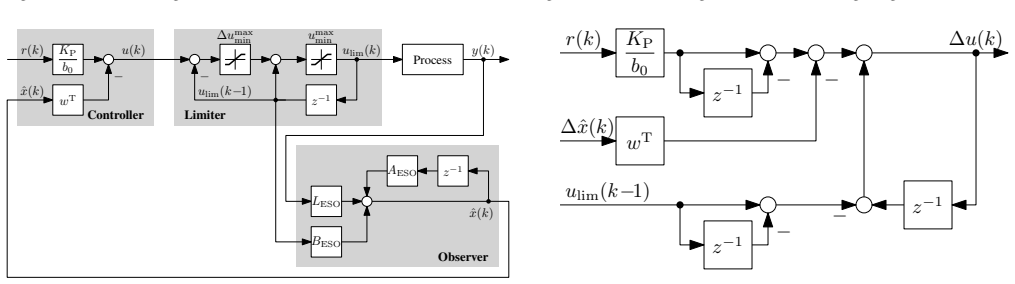
The machinery is the discrete-time extended state observer (ESO), which estimates output, derivatives, and the generalised disturbance in one update, plus a controller that uses the estimated states to cancel that disturbance. On top of this, the paper builds an incremental variant in which the controller outputs an increment of the control signal, and a magnitude/rate limiter that clips both the absolute level and the step size of that increment. The load-bearing part is the carry-over term in Eq. (22), $\Delta u(k-1) - \Delta u_{\mathrm{lim}}(k-1)$, which feeds the clipped control effort back into the next increment so the controller keeps aiming at the value it would have chosen without the limiter. Bumpless transfer is carried by the state initialisation and parameter rescaling formulas in Sect. V.
What would settle it
Let the incremental ADRC from Eq. (22) act on a plant with a known pole at the origin, drive the reference so that the rate limiter stays active for many closed-loop time constants, and record the accumulated carry-over term: if $|\Delta u(k-1)-\Delta u_{\mathrm{lim}}(k-1)|$ grows without bound or the output shows a limit cycle, the anti-windup claim fails. Equivalently, an analytical stability test of the saturated loop with the carry-over term would settle the question.
Extended reading notes
Core claim
The central claim is a complete implementation scheme for discrete-time ADRC with the practical features an industrial loop needs. For the incremental form, Eq. (22) adds the difference between the desired and the actually applied control increment at the previous step to the current increment, so the forgotten control effort is not lost when saturation or rate limiting clips the command. For bumpless transfer, the paper gives explicit formulas: initialise the observer state from the measured output and last control value (Sect. V-A), initialise the incremental term from the previous reference and limited control value when enabling the controller (Sect. V-B), and rescale the state vector and observer matrices according to the changed controller, observer, or plant-model parameter (Sect. V-C). With these steps, switching modes or changing parameters at steady state produces no visible bump in output or control signal, as the simulations in Sect. VI confirm.
Load-bearing premise
The anti-windup and bumpless behaviour rests on the assumption that feeding the limited control signal back into the observer keeps the observer's internal model consistent with the real plant, and that the carry-over term in Eq. (22) stays bounded and does not destabilise the loop during prolonged saturation; this is shown in simulation, not proven analytically.
Editorial extensions
If this is right
- A practitioner can implement ADRC in either non-incremental or incremental form, with or without magnitude and rate limiting, using only the equations collected in the paper.
- Rate limiting becomes a practical tool for ADRC: it bounds how fast the control signal can rise after reference or disturbance steps and also attenuates measurement noise in the control signal.
- Incremental ADRC can share a common limiting integrator with other incremental controllers, so switching between, say, incremental PI control and incremental ADRC is done without jumps.
- Controller and observer parameters can be changed online while the loop is running, provided the state vector is rescaled according to Sect. V-C and the change is made at steady state with $r = y$.
- The anti-windup property of feeding the limited control signal into the observer is preserved for both magnitude and rate limits.
Reading between the lines
- The promise of bumpless parameter changes is stated for steady state with $r = y$; a natural extension the author leaves implicit is a formal derivation of the state rescaling for changes during transients, where the formulas would need to account for the current tracking error.
- The carry-over term in Eq. (22) is an integral-like memory of clipped control effort; this suggests the incremental ADRC with limiter has a natural connection to classical conditional-integration anti-windup schemes, and could be compared against them on the same benchmark.
- A hardware test on a real converter or servo drive would be the next step beyond simulation; the paper's noise example already hints that rate limiting can double as a noise filter, which is worth quantifying separately.
- One could test whether the same bumpless formulas extend to adaptive or nonlinear ADRC variants, since the observer-state rescaling logic does not depend on the linear bandwidth parameterisation.
Signed reviews
Editorial analysis
A structured set of objections, weighed in public.
Referee Report
Summary. The paper presents practical implementation recipes for discrete-time active disturbance rejection control (ADRC), covering an incremental formulation, magnitude and rate limiting, and bumpless transfer between manual/automatic modes and during parameter changes. The new contributions are the incremental ADRC equations (16)-(19), the carry-over term in Eq. (22) for limited incremental control, and the bumpless parameter-change formulas in Section V-C. The claims are supported by a buck-converter simulation study in Section VI.
Significance. If the recipes are correct, the paper fills a genuine gap for practitioners by turning standard ADRC into an implementation-oriented package with explicit step-by-step instructions, including the rarely treated rate limiting. The incremental formulation and the carry-over term are plausibly new and practically useful. The derivations are largely algebraic and consistent with established anti-windup practice (Aström and Rundqvist, Ref. [20]). However, the completeness claim that 'all steps are described' for all four ADRC variants is weakened by an omission in the b0-change recipe for the non-lag-reduced variants.
major comments (1)
- [Sect. V-C.3, Eqs. (29)-(31)] The recipe for changing b0 does not state that the control-law gain vector w^T in Eq. (5)/(9) must be recomputed for the non-transformed (standard) ADRC variants. Since w^T contains an explicit 1/b0 factor, following the text literally leaves w with the old b0. In a stationary state with r=y, the control signal after the change scales as u' = (b0_new/b0_old) * u_old, producing a jump whenever b0 changes, which contradicts the paper's bumpless-transfer claim. The transformed/lag-reduced variant avoids this through the rescaling in Eq. (30), but the non-transformed non-incremental and incremental variants are left incomplete. The fix is a one-sentence instruction to recompute w^T with the new b0, and similarly to use the new w in Eq. (27) when reinitializing Δu(k-1); as written, the paper's strongest claim is not met for these variants.
minor comments (5)
- [Sect. VI-D] The simulation study does not include an example of a b0 change as described in Sect. V-C.3, despite b0 changes being one of the three parameter-change categories; adding such an example would increase confidence in the recipe.
- [Sect. V-C.3] The sentence 'changing b0 only results in a scaling factor (T^{-1} · T_old = b0_old / b0)' is easy to misread; the intended factor is the ratio b0^old/b0, and the notation should be made explicit, e.g., using a superscript 'old' throughout.
- [References] Ref. [20] spells the second author's name 'Rundqwist'; the correct spelling is 'Rundqvist'.
- [Fig. 14 caption] The phrase '400 % increased closed-loop settling time' is ambiguous; it should state the old and new settling times explicitly (e.g., 'from 2 ms to 10 ms').
- [Sect. IV, Eq. (22)] A brief intuitive explanation of why the carry-over term prevents stationary error during limiting would be helpful; currently the anti-windup rationale is implicit.
Circularity Check
No significant circularity: incremental and bumpless-transfer equations are algebraic implementation identities, not fitted predictions.
full rationale
The paper's derivations are algebraic implementation recipes rather than empirical predictions. The incremental ADRC equations (16)-(19) are obtained by direct substitution into the standard discrete-time observer and control law: (17) is substituted into (7) to get (16), and (19) is substituted into (9) to get (18). This is an identity transformation, not a fitted input called a prediction. The carry-over term in Eq. (22) is introduced as a design mechanism to preserve the desired control signal during limitation; it is not derived from data and does not smuggle in the target result. The bumpless-transfer initialization (27) sets the previous increment so that the first enabled control output matches the manual value; this is by construction, but as an implementation recipe and not as a circular proof of a separate claim. The lag-reduced form and the windup discussion are cited from the author's prior work [17], but the central new contributions (incremental formulation, rate limitation, bumpless parameter changes) do not reduce to that citation; the lag-reduced variant is presented as an optional alternative, and the paper's own equations for the non-lag-reduced variants stand independently. The skeptic's noted gap in Sect. V-C.3, where the control-law gain w is not explicitly recomputed after a b0 change in the non-transformed variants, is a completeness or correctness concern, not a circularity. No fitted parameters appear, and no prediction is equivalent to its own input. Overall, the derivation chain is self-contained apart from ordinary background citations, so the circularity score is 0.
Assumptions & free parameters
assumptions (4)
- domain assumption The plant can be represented as a low-order integrator chain with a generalized disturbance f(t) that the extended state observer can estimate.
- domain assumption Feeding the limited control signal into the observer prevents integral windup (Sect. IV, citing [20]).
- domain assumption Bumpless transfer guidelines assume stationary state with r=y (Sect. V).
- standard math Zero-order hold discretization of the continuous-time plant matrices is valid.
Cite this review
Pith. "Pith review of Practical Active Disturbance Rejection Control: Bumpless Transfer, Rate Limitation and Incremental Algorithm." pith.science (2026). https://pith.science/paper/YRJ6CP42
@misc{pith2026190804610,
  author       = {Pith},
  title        = {Pith review of: Practical Active Disturbance Rejection Control: Bumpless Transfer, Rate Limitation and Incremental Algorithm},
  year         = {2026},
  howpublished = {\url{https://pith.science/paper/YRJ6CP42}},
  note         = {Machine review of arXiv:1908.04610}
}
read the original abstract
Practical applications of controllers often impose further requirements on the implementation beyond the actual control performance, such as the ability to switch between manual and automatic control or between different control laws or controller parameter settings, known as bumpless transfer. Another common requirement is to limit the control signal in magnitude and/or rate. This article examines and extends several discrete-time variants of active disturbance rejection control (ADRC), which is increasingly being applied especially in the field of power electronics and drives, in this regard. Detailed guidelines for practical ADRC implementations with these abilities are presented, and all features are being demonstrated with the help of simulation examples.
Figures


Figures from the paper (6 more)



Reference graph
Works this paper leans on
-
[17]
G. Herbst, “A simulative study on active disturbance rejection control (ADRC) as a control tool for practitioners,” Electronics, vol. 2, no. 3, pp. 246–279, 2013
work page 2013
-
[20]
Integrator windup and how to avoid it,
K. J. ˚Astr¨om and L. Rundqwist, “Integrator windup and how to avoid it,” in American Control Conference , 1989, pp. 1693–1698
work page 1989
-
[1]
From PID to active disturbance rejection control,
J. Han, “From PID to active disturbance rejection control,” IEEE Transactions on Industrial Electronics, vol. 56, no. 3, pp. 900–906, 2009
work page 2009
-
[2]
Active disturbance rejection control: A paradigm shift in feedback control system design,
Z. Gao, “Active disturbance rejection control: A paradigm shift in feedback control system design,” in Proceedings of the 2006 American Control Conference, 2006, pp. 2399–2405
work page 2006
-
[3]
On the centrality of disturbance rejection in automatic control,
——, “On the centrality of disturbance rejection in automatic control,” ISA Transactions, vol. 53, no. 4, pp. 850–857, 2014
work page 2014
-
[4]
Tuning method for second-order active disturbance rejection control,
X. Chen, D. Li, Z. Gao, and C. Wang, “Tuning method for second-order active disturbance rejection control,” in Proceedings of the 30th Chinese Control Conference, 2011, pp. 6322–6327
work page 2011
-
[5]
Modified active disturbance rejection control for time-delay systems,
S. Zhao and Z. Gao, “Modified active disturbance rejection control for time-delay systems,” ISA Transactions , vol. 53, no. 4, pp. 882–888, 2014
work page 2014
-
[6]
Q. Zheng, “On active disturbance rejection control: Stability analysis and applications in disturbance decoupling control,” Ph.D. dissertation, Cleveland State University, Department of Electrical and Computer Engineering, 2009
work page 2009
Show all 22 references
-
[7]
On practical applications of active disturbance rejection control,
Q. Zheng and Z. Gao, “On practical applications of active disturbance rejection control,” in Proceedings of the 29th Chinese Control Confer- ence, 2010, pp. 6095–6100
2010
-
[8]
A DSP-based active disturbance rejection control design for a 1-kW H-bridge DC-DC power converter,
B. Sun and Z. Gao, “A DSP-based active disturbance rejection control design for a 1-kW H-bridge DC-DC power converter,” IEEE Transac- tions on Industrial Electronics , vol. 52, no. 5, pp. 1271–1277, 2005
2005
-
[9]
A novel control method for transformerless h-bridge cascaded STATCOM with star configuration,
R. Xu, Y . Yu, R. Yang, G. Wang, D. Xu, B. Li, and S. Sui, “A novel control method for transformerless h-bridge cascaded STATCOM with star configuration,” IEEE Transactions on Power Electronics , vol. 30, no. 3, pp. 1189–1202, 2015
2015
-
[10]
Automatic disturbances rejection controller for precise motion control of permanent-magnet synchronous motors,
Y . X. Su, C. H. Zheng, and B. Y . Duan, “Automatic disturbances rejection controller for precise motion control of permanent-magnet synchronous motors,” IEEE Transactions on Industrial Electronics , vol. 52, no. 3, pp. 814–823, 2005
2005
-
[11]
On the control of the permanent magnet synchronous motor: An active disturbance rejection control approach,
H. Sira-Ram ´ırez, J. Linares-Flores, C. Garca-Rodriguez, and M. A. Contreras-Ordaz, “On the control of the permanent magnet synchronous motor: An active disturbance rejection control approach,” IEEE Trans- actions on Control Systems Technology , 2014
2014
-
[12]
Frequency-domain analysis of nonlinear active disturbance rejection control via the describing function method,
D. Wu and K. Chen, “Frequency-domain analysis of nonlinear active disturbance rejection control via the describing function method,” IEEE Transactions on Industrial Electronics , vol. 60, no. 9, pp. 3906–3914, 2013
2013
-
[13]
Robust speed control of induction motor drives using first-order auto-disturbance rejection controllers,
J. Li, H.-P. Ren, and Y .-R. Zhong, “Robust speed control of induction motor drives using first-order auto-disturbance rejection controllers,” IEEE Transactions on Industry Applications , vol. 51, no. 1, pp. 712–720, 2015
2015
-
[14]
Development and active disturbance rejection control of a compliant micro-/nanopositioning piezostage with dual mode,
H. Tang and Y . Li, “Development and active disturbance rejection control of a compliant micro-/nanopositioning piezostage with dual mode,” IEEE Transactions on Industrial Electronics , vol. 61, no. 3, pp. 1475– 1492, 2014
2014
-
[15]
ADRC with adaptive extended state observer and its application to air-fuel ratio control in gasoline engines,
W. Xue, W. Bai, S. Yang, K. Song, Y . Huang, and H. Xie, “ADRC with adaptive extended state observer and its application to air-fuel ratio control in gasoline engines,” IEEE Transactions on Industrial Electronics, vol. 62, no. 9, pp. 5847–5857, 2015
2015
-
[16]
Active disturbance rejection position control for a magnetic rodless pneumatic cylinder,
L. Zhao, Y . Yang, Y . Xia, and Z. Liu, “Active disturbance rejection position control for a magnetic rodless pneumatic cylinder,” IEEE Transactions on Industrial Electronics , vol. 62, no. 9, pp. 5838–5846, 2015
2015
-
[18]
Scaling and bandwidth-parameterization based controller tun- ing,
Z. Gao, “Scaling and bandwidth-parameterization based controller tun- ing,” in Proceedings of the 2003 American Control Conference , 2003, pp. 4989–4996
2003
-
[19]
Discrete implementation and generalization of the extended state observer,
R. Miklosovic, A. Radke, and Z. Gao, “Discrete implementation and generalization of the extended state observer,” in Proceedings of the 2006 American Control Conference , 2006, pp. 2209–2214
2006
-
[21]
A new, continuous-time model for current-mode control,
R. B. Ridley, “A new, continuous-time model for current-mode control,” IEEE Transactions on Power Electronics , vol. 6, no. 2, pp. 271–280, 1991
1991
-
[22]
Microcontroller-based peak current mode control using digital slope compensation,
M. Hallworth and S. A. Shirsavar, “Microcontroller-based peak current mode control using digital slope compensation,” IEEE Transactions on Power Electronics, vol. 27, no. 7, pp. 3340–3351, 2012
2012
Reviewed August 14, 2026 · model on record in the stance chip above.
Discussion (0). Continue with ORCID to comment.